Electronics Design (Mar. 2)
Process
Below you will find my dictation, notes and documentation about the processes I went throught with regards to using the Eagle software to recreate the Echo Hello World board as well as using the programming of the board. Each of the topics will be covered in seperate sections. A link at the bottom of the page will take you to all of the files that I created for this exercise. The orginal echo hello world board was used as the starting point for the work I completed in this exercise. A LED and a Button were added to the board design as well as a resistor with the LED. Over all, I used a 449 and 10K resistors, LED, a button, ATTINY44 IC, two types of jumpers, 1 uF capacitor, avraismd , and a resonator. For more information about Exercise 6.
Eagle
I began the process by following the tutorial OtherPlane Tutorial. I already had the Eagle software installed on my computer. Next, I downloaded the adafruit library. TheAdafruit zip file was than installed and opened. I ran into the issue of followign the directions, but there was a mistake in them. Instead of creating a lirbaries foloder in your Eagle folder, you need to add the open adafruit lirbrary to the libr folder that is already in Eagle. This will allow you to find the adafruit library. If you do not do this process, you will not be able to access your needed library.
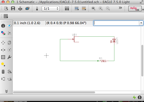
Next, I followed the tutorial to create a small battery powered board with a resistor and LED. I learned how to group parts, add lines, delete parts, change the flow of material, traces for autorouter, move pieces, rotate pieces, creating pads and holes, and more. Over all, it taught me how to make a schematic and a board in Eagle. This gives me the ability to create a baord to cut out on the OtherMill. When I autotraced I changed the top to * and bottom to N/A. I learned to use the hole tool throigh Via, which gives you the baility cut holes in different diameters, sizes and thickness. When creating a outside cutting layout you need to change the Layer 1, which the boards main compents are located, to layer 20, which is going to become the outside cutting outline. You can use the rip up tool to make changes to your trace connections on your board.
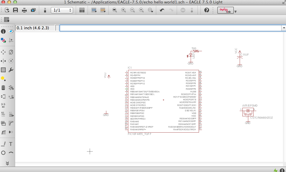
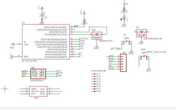
I than looked at Terence's board he created by looking at his exercise week 6 process. This helped to began looking for parts to redesign the echo hello world board. I seearch through the library looking for the parts one by one. I than realzied I cpould search by specifc titles, such as GND, IC, UF and etc. This end up helping speed up the search. I ran into an issue trying to find all of the aparts at times, so installed more libraries, such as the SparkFun lib. This allowed me to keep search for more parts. Also, I learned how to rename parts by typing in a new name and than clicking. I had problems finding the ATTINY44, so I searched for more libraries. I found theattiny44 eagle file and used it. The largest issue I had was finding the correct parts. I learned that element14 has a large amount of libraries as well as the Eagle software comes with a lot. You can see that I missing parts and/or having the incorrect part in the schematic below:
I did learn how to name parts and draw connecting wires. Using the search feature can be helpful if you opened the library under USE, if not it is a pain in the neck. So make sure you use the correct library. Also, I do not like the fact you can only have one schematic open at a time. Next, a colleague of mine found a a schematic and brd file from a previous fab lab student. I used this to copy the corrects parts I need to redraw the board to make it my own. When you go to copy it is important to group the parts and than copy them. This will close the software and open a new schematic. Now, I began deleting pieces and putting new ones in to show that I actually know how to do this process. This was time consuming, but easy since I spent hours last night learning to search for parts, naming, connecting and moving them all around. This took time because I was not 100% sure about making the connections.
Than I found out that there was a Fab Lab Library for Eagle that was sent out in an email today. I than began using this library to move forward. This made my process so much easier. I could find all of the parts except the jumper part. I end up needing to copy the jumper from the previous file. I used the wire tool to connect all of the parts I need too. I used the VCC and the GND from other libraries on Eagle. I than connected the parts and used the name and label tool to create names/connections for the ATTINY44, AVRISPMD,and the rest of the parts. I used the value tool to change the values of the resistors and the capacitors. The technology tool is helpful for identifying parts information.
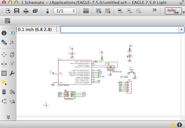
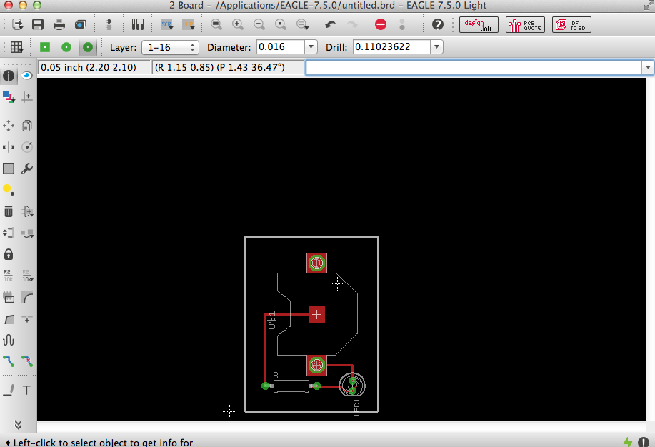
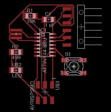
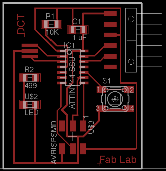
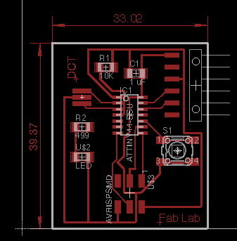
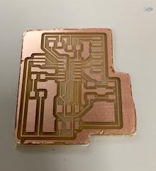
Finally, I went to file and went from schematic to board to begin the creation of the board process. I first moved all of the parts around the board while looking at a screen shot of Neal's board as well as Terence's design too, so I could place my parts in a functional layout. I was able to move the parts to a similar layout as Neal's and than autorouted the board. I set the top to * and the bottom to N/A. I ran the process and ended up with a few issues that made me learn how to create my own traces. I did this by using the wire tool to begin drawing connections as well as the LED and R2 weren't connected to the IC as well as the button was missing routes. I than traced my traces to make connections as well as used the route and ripup tools to make changes to the autorouter. This took some time to do, because I need to make sure pathways worked as well as used the different line tools styles as well as widths to make the functional pathway. I did this to make my paths work when I recieved the yellow lines that show connections that did not autoroute. After making the process work, the yellow lines delete from the board. I than put on layer 20 and created a grey box around my board. Lastly, I used the text tool to put my initials, DCT, and Fab Lab on the board. Plus, I used the measurement tool to demonsion the board. You can see this in my images below:
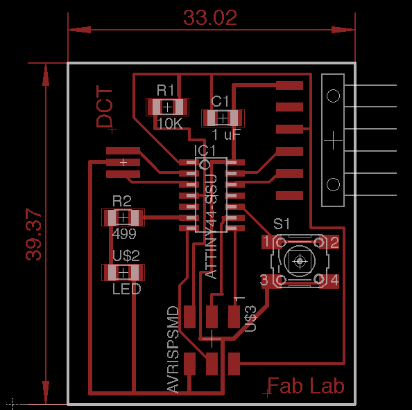
After posting the images above, I realized that I didn't route and connect the LED and R1 to the IC ATTINY44. I went back and fixed this issue.
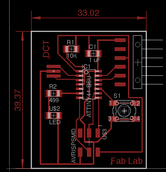
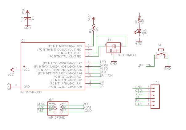
I than realized I had another mistake in my design. So I made the wires smaller as well as under View, I changed the schematic size grid which allowed me to to make the wire connections easier as well as changing the thickness of the wire. Lastly, a colleague showed me that I did not connect the top R1 with my bottom connection pin in the top right. You can see these fixes in the image below:
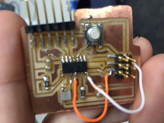
For the time begin, I added to jumper wires and made a solder bridge to this board.
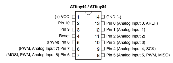
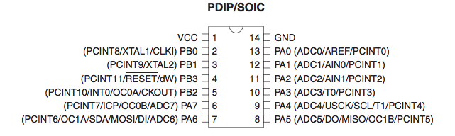
Diagrams below are very helpful for identifying the correction pins when designing your board with regards to inputs, inputs, and etc:
I also went back into my schematic and board files in Eagle to make adjustments to my paths, so they would have cleaner connections as well as a little bit thicker paths too. I felt that making these adjustments would make my second board better. Also, I will use thicker jumper pins so it will be tighter with the programmer cable from adafruit. Lastly, I will double check that the LED is facing the correct direction with regards to the path and the green line on the LED.
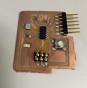
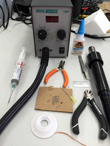
Soldering
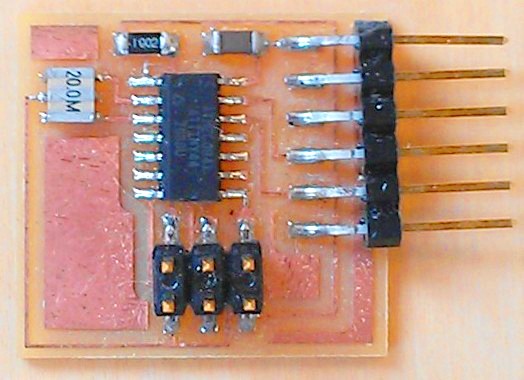
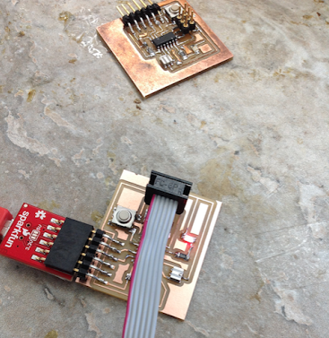
I cut my board and realized that I did not cut the original outline on my board in Eagle, because, I thought this was a work plane. I cut the board manually. Next, I realized my wire from the top resistor was touching some of the padson the IC. I took a new, thin razor and cut a line to disconnect the problem. I than soldered the parts on the board by using solder past and a heat gun with the use of twizzers and snips. You need to check that the LED's green sign on the back is going to the positve side. I learned that it was easier to use the heat gun on parts that would keep moving, such as the jumpers and IC, than doing all the parts at once. It is also important to check that you do not have any connections touching that you should have connected. I found one that was slightly touching a pad and I used a razor to cut it. Constantly checking your work in your design and in the physical cretaion helps to keep you from making mistakes.
Code
Tom, Ian and I began working on the coding aspect of loading the IC. We end up running into the same issues as before with the ISP. We agree that we are having some type of human error. We learned that it is important to make sure you have the correct name for the IC, which was tiny44 for attiny44, since we were using a non fab lab bootloader due to having issues with the ISP. We use the correct process with the avrdude and tried programming an Arduino and used the device code of atmega328p and ran into the same issue. This error message would take place after we would run make fuse, but the make clean and make hex would work correctly. Even saving the makefile would work too. You can see this in the images below:
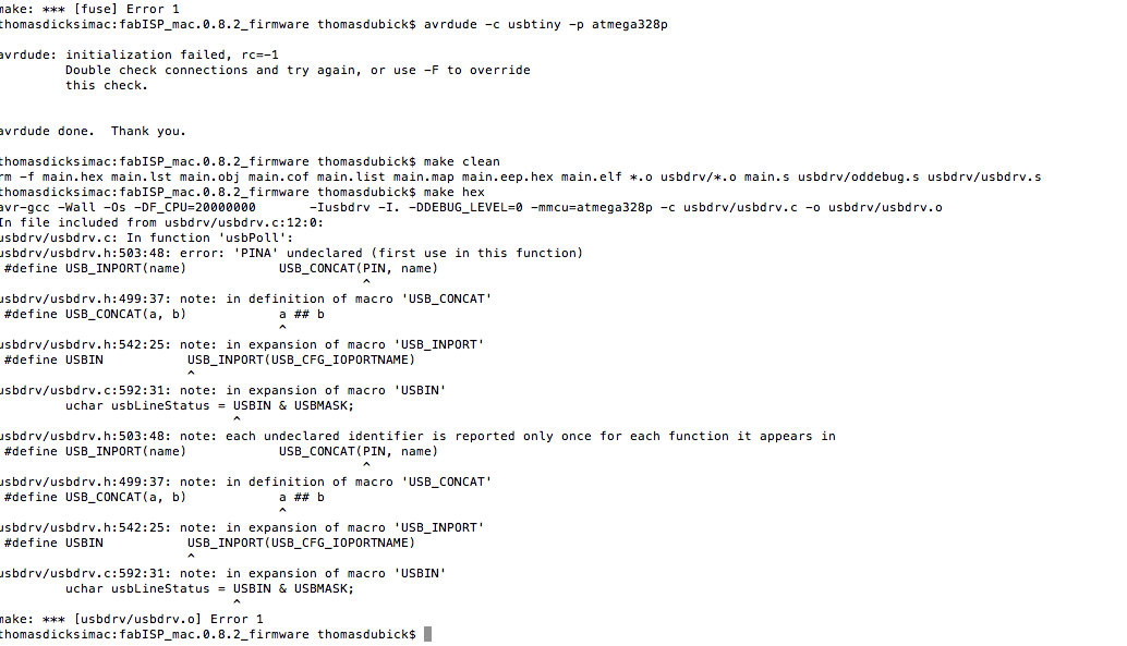
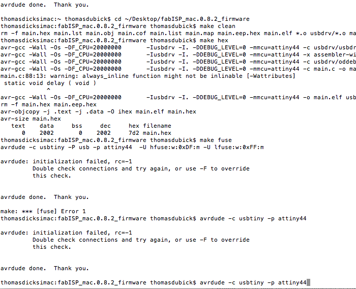
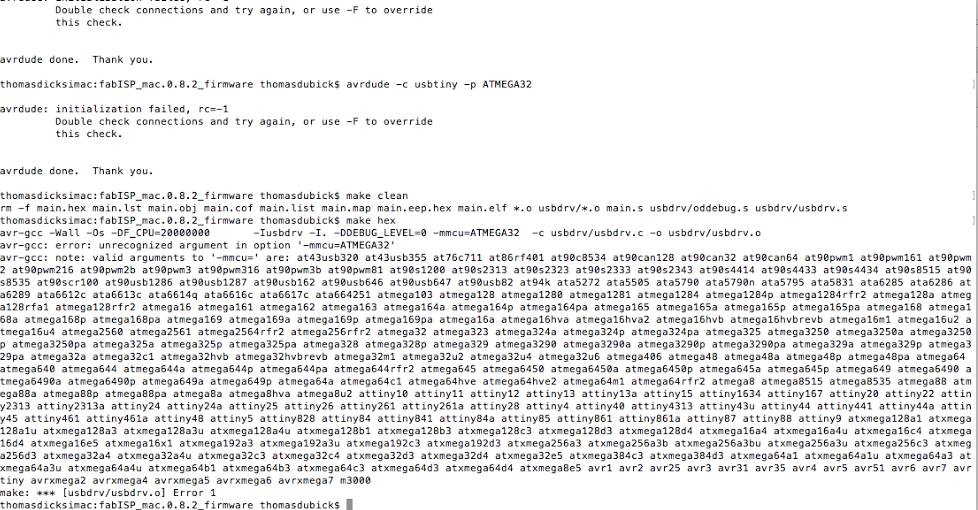
We did a internet search of the error, but could not find any help. I think we are just needing some help here. We will keep working and looking for answers, but as a group and as an individual, it is a struggle with electronics so far.
Finally, got the board to work. I ran my a blink code I created in C.
Project Files
This is a button to access the files created for this exercise course for all of the above softwares.