Outputs Devices (Apr. 27)
Process
Below you will find my dictation, notes and documentation about the processes I went throught with regards to completing the Outputs exercise. Each of the step and processs will be covered in seperate sections. A link at the bottom of the page will take you to all of the files that I created for this exercise.
Planning
I worked with Terence to plannout my servo output board. He reviewed Neal's design with me. I told him I wanted to add a LED connection jumper from PB2 with the plan of using this board as part of my final project. I used Neal's design as the foundation for my own board. I also looked at previous Fab Lab student's sites for support. I looked at Adolfo Gutiérrez Sánchez's, Fabrico Santo's, and Chris Carter's Fab Lab pages on Outputs. I found this to be very helpful with designing and programmming my board.
Eagle
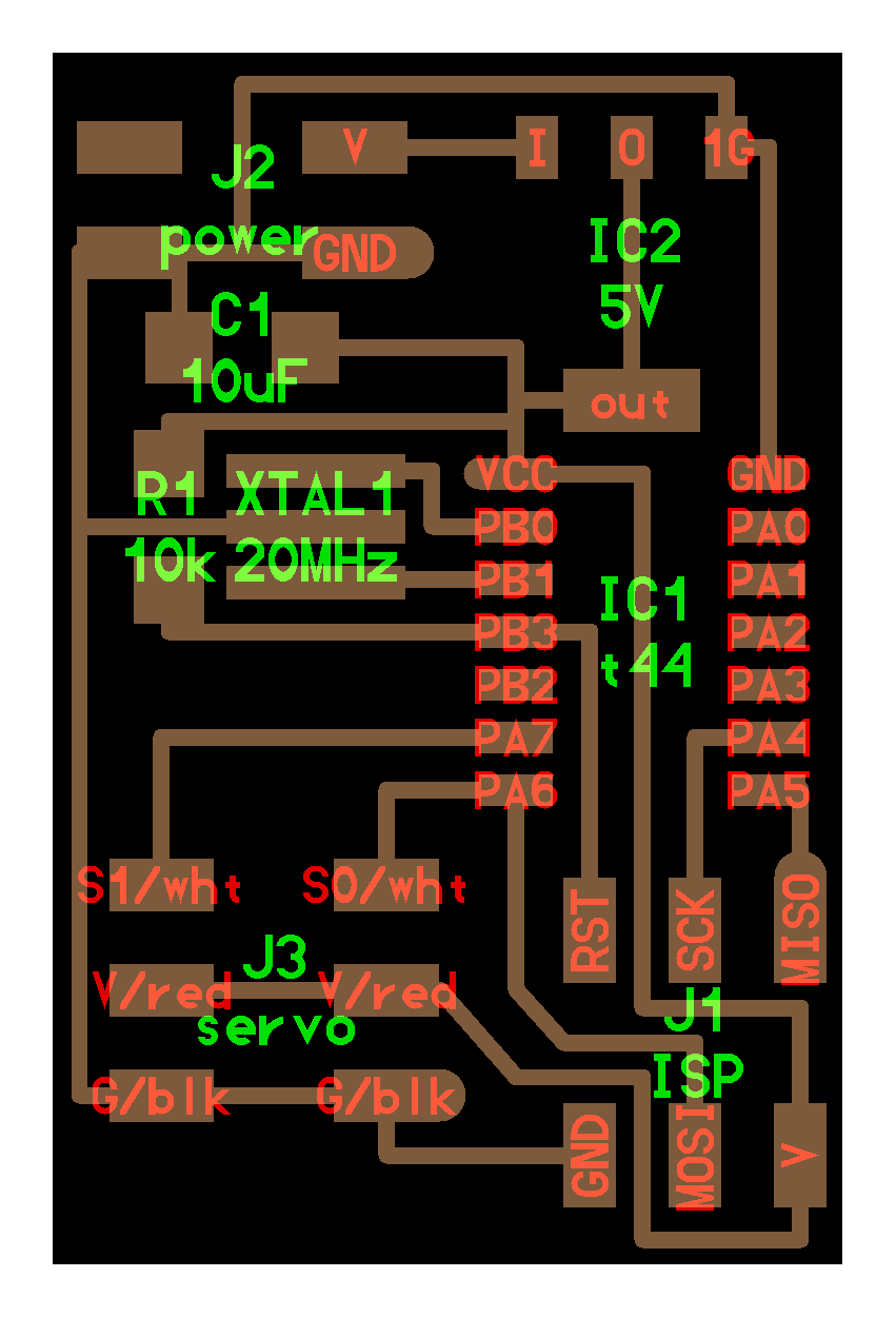
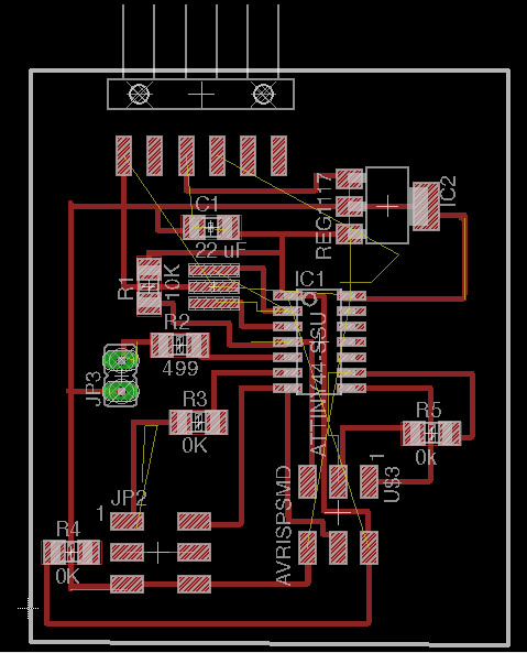
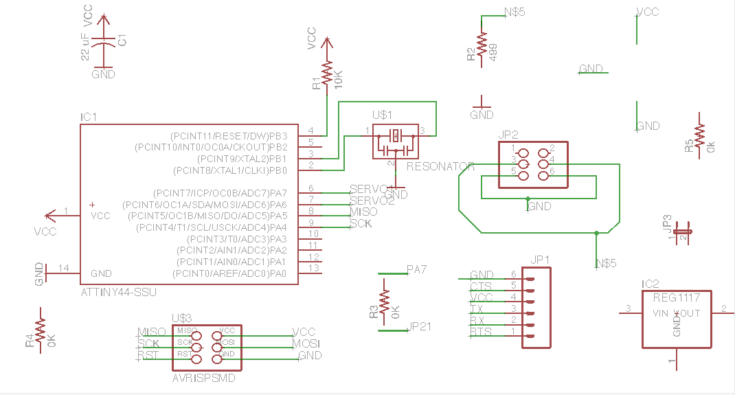
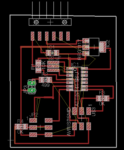
I created my schematic using Eagle. I opened a my hello.world board to use as my base, so I would not need to go and find all of the parts. Terence helped me find the mosfet peice, because, I was not aware of it. After creating the schematic, I made the board. I did have some issues with creating the create wire paths in the schematic as well as the board due to my software not working correctly. I would try to make a wire connection, but the tool would not locate the correct location. I closed the software and even had colleagues look at it. I could not find a solution, so I just kept moving forward and ignored the yellow wires. I used a few 0K resistors as jumpers. I used the servo plane by Neal, but I added a break out LED jumpr pins with a 49.9k resistor to PB2, so I could code a LED as well. I did this because I was planning a head for my final project that involves a Batman spotlight that moves with two servo motors. My board has two servo motors and a LED pin connection point. You can see my schematic and board below:

Lastly, I took out the jumper pads for the LED break out pins, because, they kept ripping the pads off due to not having enough support. I replaced them with a two pin through hole jumper pins instead. These were much stronger.
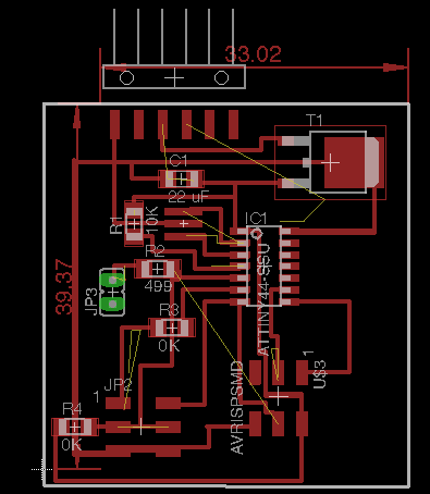
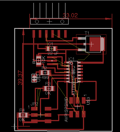
Once again, I reviewed my board and realized that I had some wires missing. This happen between the PB3 and the RST connections. I keep comparing ym board back and forth to Neal's servo board. Furthermore, I realized that I accidently deleted some wires acrtoss my board. I had Terence check my board and he pointed out that I may have too many wires running under my IC as well as that my LED and pin had straight VCC connected, which would power it all the time. This helped me a lot. I made changes to my board to fix these issues. You can see the changes in the images below:
Soldering
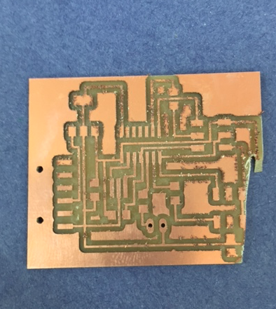
I made two soldering boards, which neither of them worked. The first board began getting very hot. I thought the issue was the fact that the wrong bit was used on the other mill, because, one of my students switched the bit on me as well as removed the board, which lead to me finishing the cuts with a razor blade. I thought that made it was creating a short. Furthermore, Neal's board has a 22uF capacitor on it, which is not in the inventory. I tried using a 10uF but had no success. Plus, I made a mistake and used a Mosfett instead of a resonator on the board. Lastly, I forgot a trace wire too. Long story short, there were a lot of mistakes on this board.
The large amount of mistakes on the first attempted baord lead to me double checking my Eagle files and cutting another board. The second board ended up heating up again. I believe the issue is the fact that the wrong capacitor is being used. I used the 10uF again. I looked up again on the inventory for the 22uF, but could not find it. Furthermore, I checked DigiKey's site and they do not even carry one. DigiKey does carry a 0.22uF. I checked with Terence and he stated he would look in to it for me.
Terence told me to use two 10uF capacitors instead of a 22uF. I did this by stacking the two 10uFs on top of one another and soldering them. This put them in parrallel, which increased their capacity.
When I cut my board, I had some difficulties a few times. This new board shifted on me and end up with a large cut write through it. I had to to cut it again. Moral of the story is to make sure you have enought tape holding your board down.
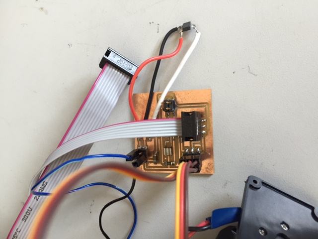
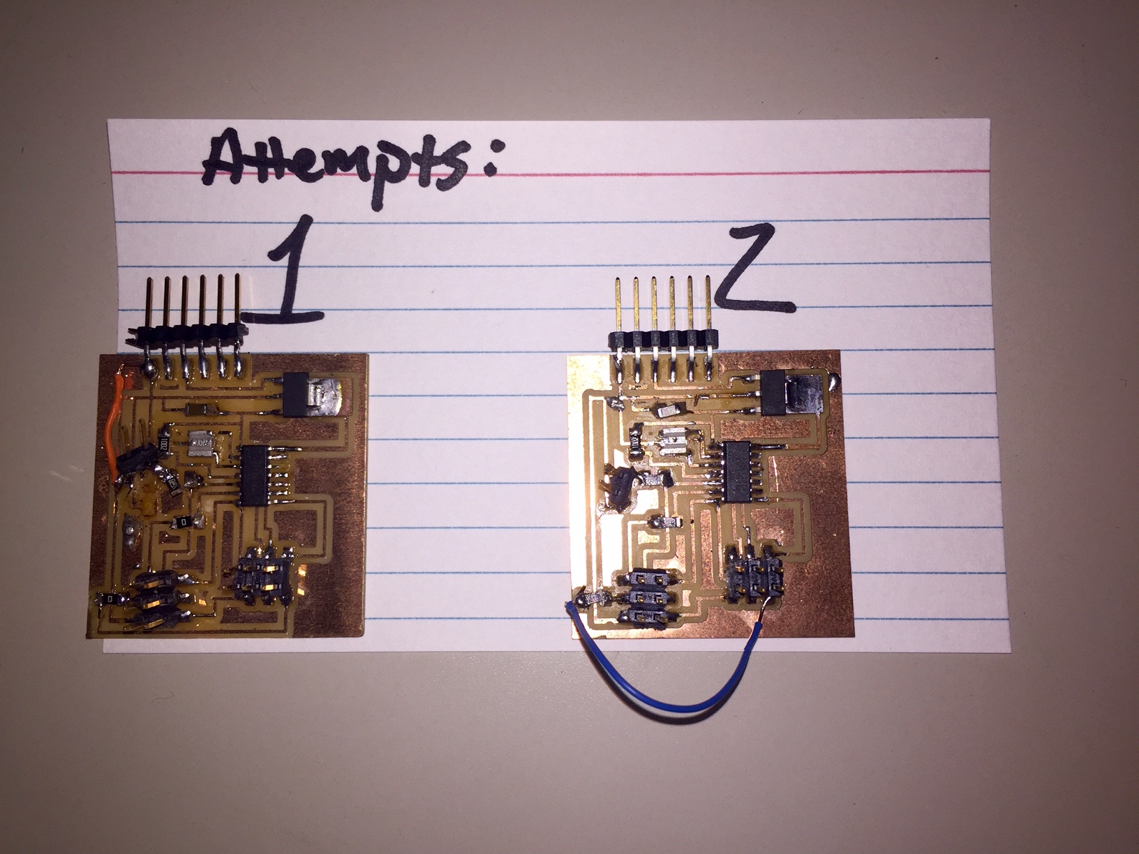
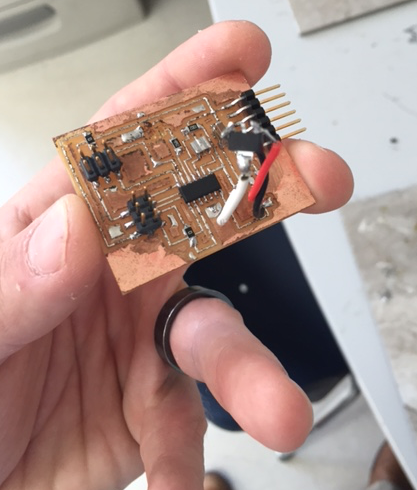
No matter what I do my boards IC 5V regulator over heats. I have made multiple boards and even made a version of Neals's baord, and they all over heat. I have asked Terence for help on this issue. I am extremely frustrated. I have made multiple boards and spent over 60 hours on this project. I have soldered multiple boards and researched a lot of code and previous Fab students, and I am still making little to no progress. Below are images of my latest board creation as well as a Neal like board:
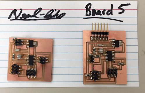
The IC 5V regulator continues to get extremely hot as well as smoke.
The the batch of regulators end up being bad. Terence tested multiple regulators and each one smoked. He showed me how to attach a 9v battery using aligator clips to the VCC and the back GND as well as using a multimeter on the output vcc to emasure the drop in voltage. The over heating burnout each regualtor that was tested. The good news here is I designed the board correctly. Furthermore, all I need to do is switch out the regualro on my previous boards.
The batch of regulators were not bad. After Adam looked at the specs for it, he noticed the pin layout was different than Neal's. This layout was not on the inventory. In the end, I had to solder jumper wires to the regulator from the VCC in, VCC out and the GND to make it work.
Final Project Coding
I used the basic blink and servo sweep that comes with the Arduino software as the foundation for my code. I also used high low tech and adafruit to help with my coding. The image below is my code: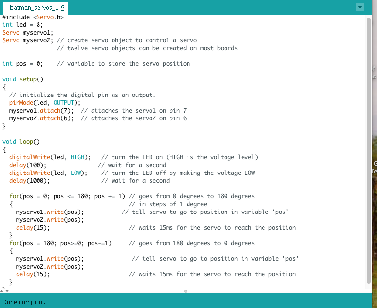
I used the High Low Tech page to help with wiring and coding.
Success
I used a board designed by Santos Fabricio. I did this after a long time struggling to get my board to work correctly after 9 attempts. I used the foundation from the servo sweep to make my code for my servo motor. Below you can see my video of my servo working and an image of the code. I am so excited to final have this section completed after the long struggle I went through to get it to work. Plus, I learned that it is important to udnerstand the specs of a regulator. I had to add extra wire to make my regulator work. I also learned that it is important to use a 360 degree servo versus a 180 degree due to the motor locking on the turns.