<-- Week 14
WEEK 15
[ NETWORKING AND COMMUNICATION ]
Week 16 -->

WEEK'S GOALS:
IDEAS THIS WEEK:
i. Board 1 communicating with Board 2 via Asynchronous Networking.ii. Board 1 with LDR and Bluetooth communicating with Board 2 with LED and bluetooth.
iii. Board 1 with Gas sensor and Bluetooth communicating with Board 2 with DC Motor and bluetooth.
iv. Board 1 with LDR and Bluetooth communicating with Board 2 with Stepper Motor and bluetooth.
ACHIEVEMENTS THIS WEEK:
(i) Asynchronous Networking
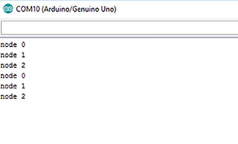
BOARD 1 Communicating with BOARD 2 via asynchronous networking- Helps communicate between two boards with wires
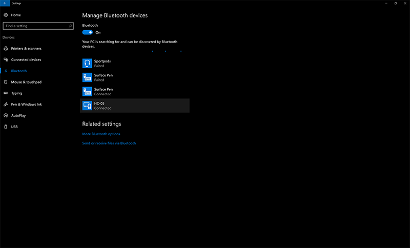
(i) Wireless Networking
BOARD 1 Communicating with BOARD 2 via wired and with phone via Bluetooth Module- Helps communicate between two boards with wires with bridge board communicating with phone's IDE
TASKS AT HAND:
- NO PENDING TASK

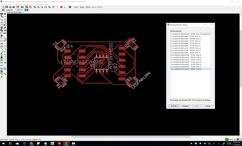
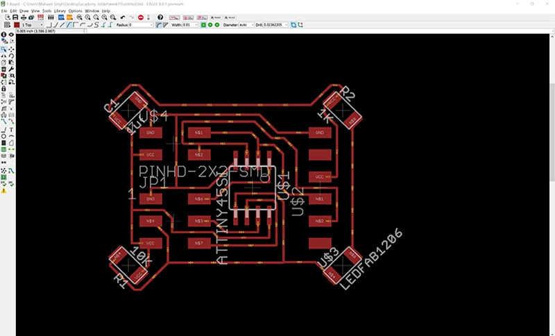
Schematic Preperation on EAGLE

PCB Milling
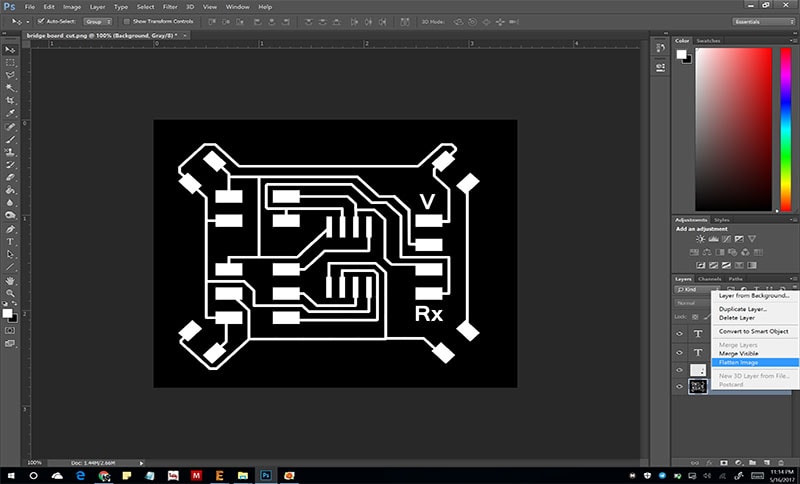
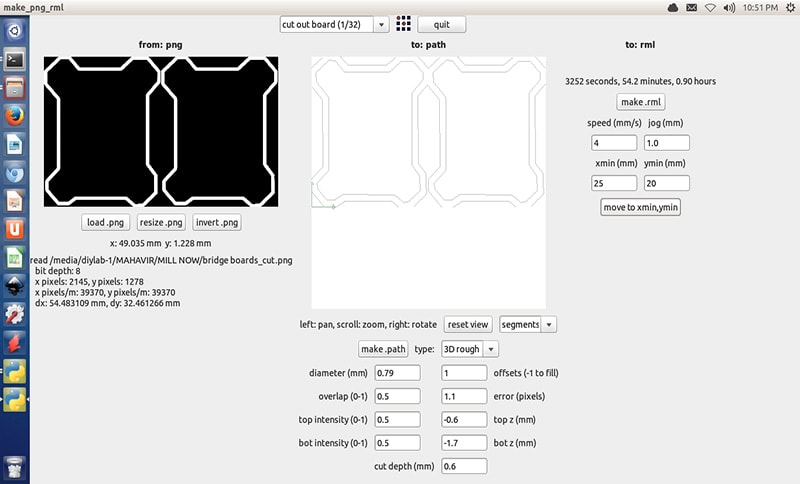
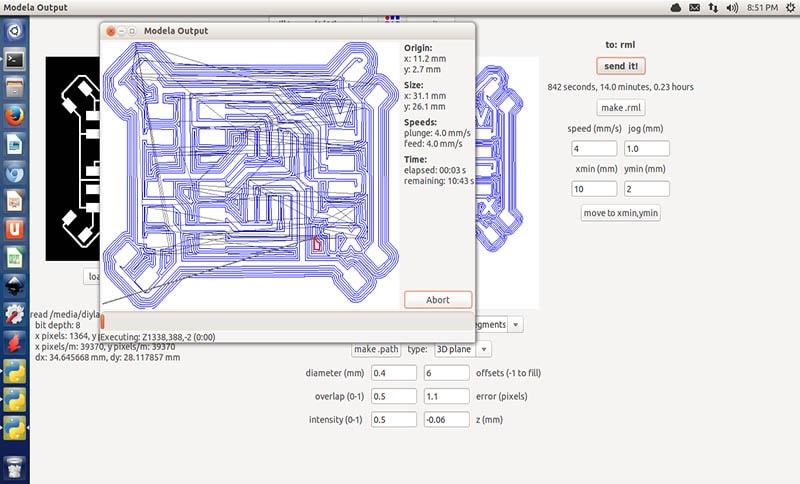
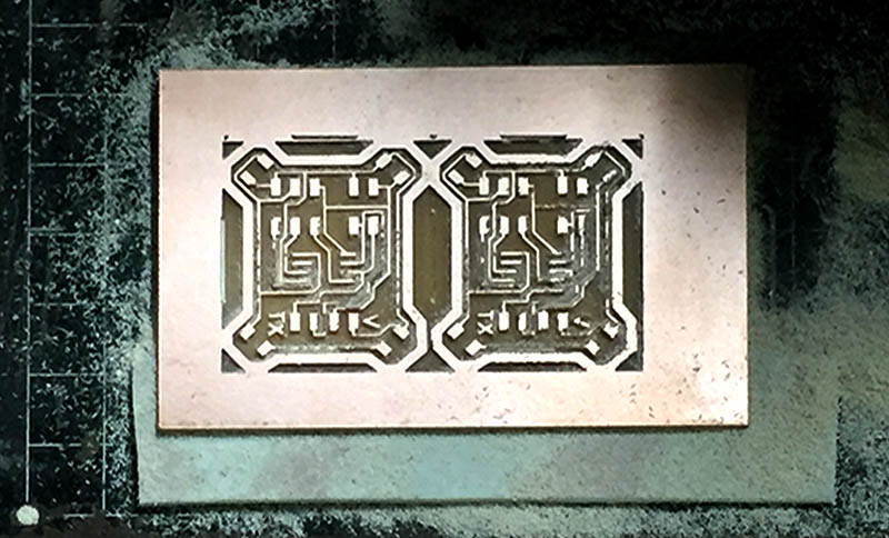
Milling two boards from the same PCB with just one file

This week saw a lot of boards being milled by everyone in the academy. I felt the size of each node wasnt so big to waste FR boards so much. I clubbed the two traes and two cut files as single images and the result came out to be beautiful.
.jpg)
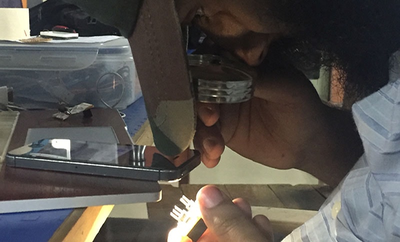
Clearning|Stuffing
Stuffing all boards with components as per archieve instructions

Satisfied on saving an extra PCB
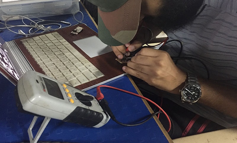
Programming
Editing Make file's Node ids

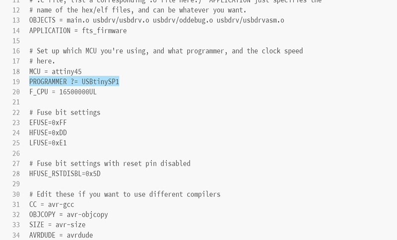
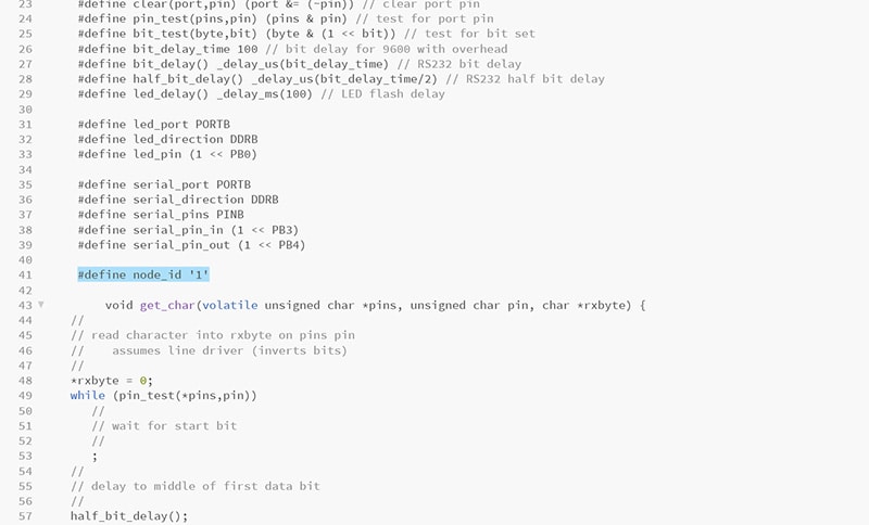
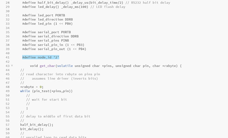
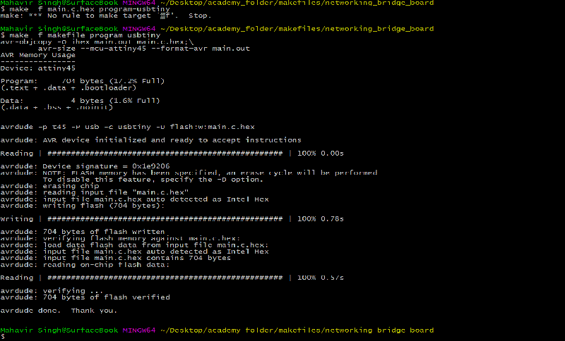
Programming each Node one by one with FAB ISP

Using Ribbon wires with 8 pin connector heads(only 4 being used from that) to connect all boards to bridge

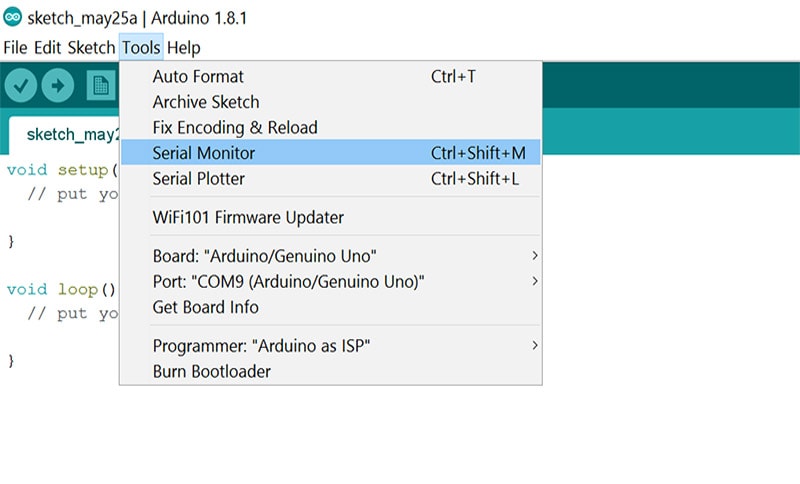
NETWORKING VIDEO
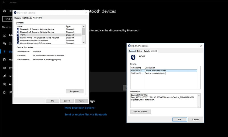
The video below explains all the steps to make this workBluetooth module enabling wireless networking through a bridge and node
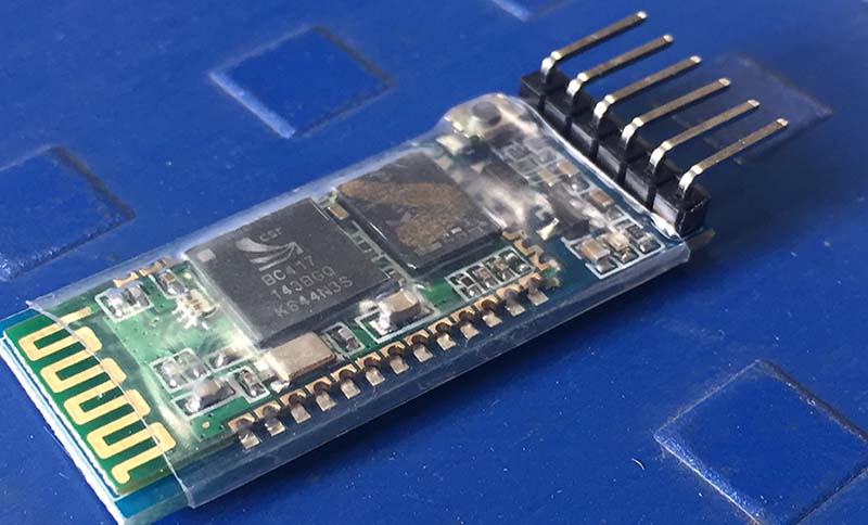
So this was the interesting part, I took the order displayed on the bluetooth module's pins, interchanged rx with tx and made my traces according to that. This helped me directly connect the bluetooth module with my board without any wires. Another thing i did was mark 'V' above and 'tx' on the last pin to help me connect in the order-V, G, RX, TX and bluetoothe being 'V,G'Tx,RX. Bluetooth works woderfully now.Connecting Bluetooth Module to board directly without Jumpers


WORKING VIDEO Had thought to make smilies on the boards and make them wink to each other when each one talks to us on serial monitor by drawing eyes around each of these board's LED over tape. Dint work out well. You can make out from the white tape over my board.
FTDI Pinout
DUE TO UNAVAILABILITY OF FTDI IN THE LAB DURING THE WEEK OF THIS ASSIGNMENT, I WENT AHEAD TO REMOVE THE IC OF AN ARDUINO UNO TO CONVERT IT AND USE IT LIKE A FTDI CABLE>


