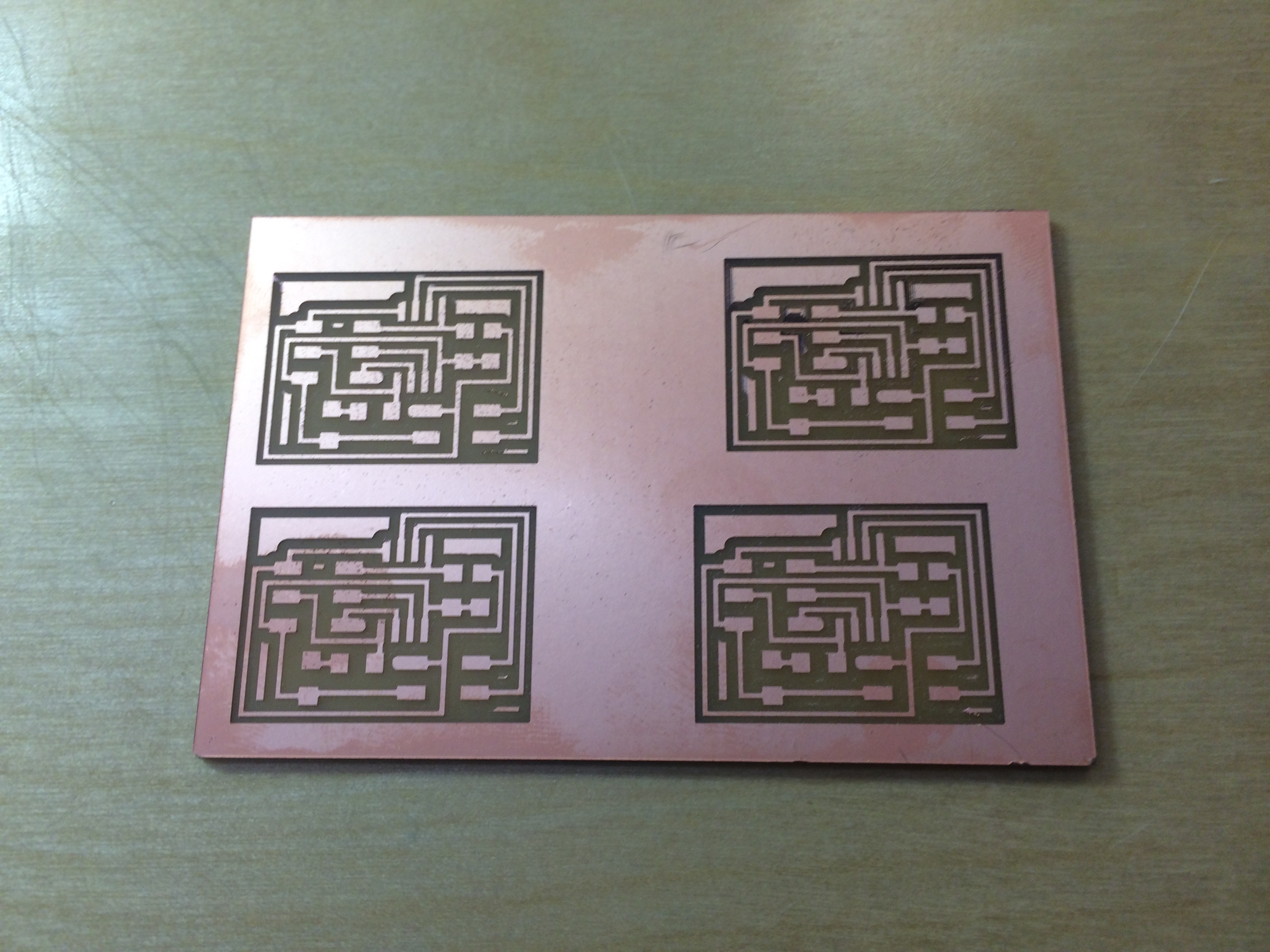
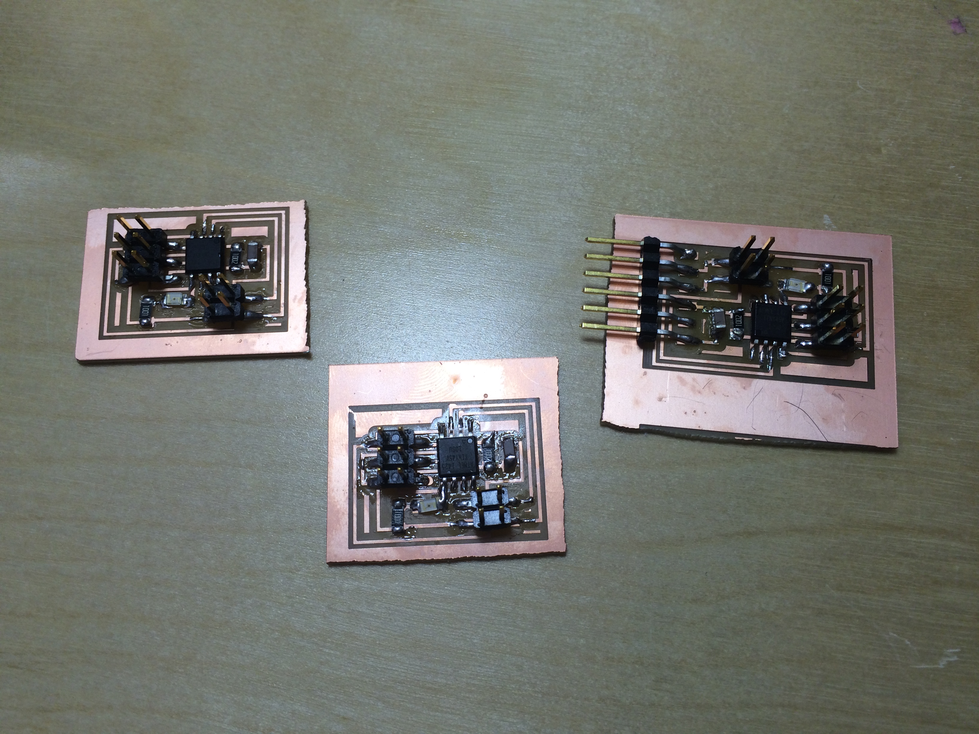
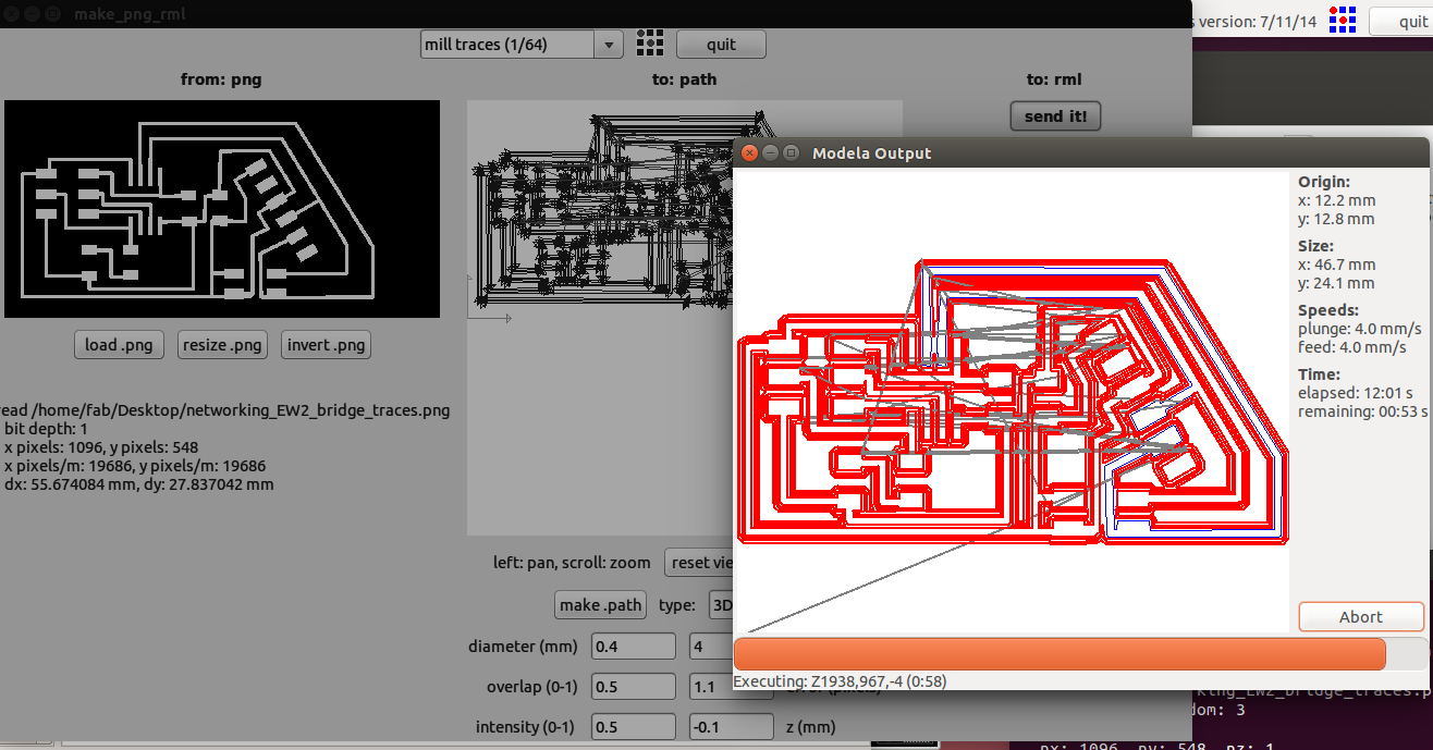
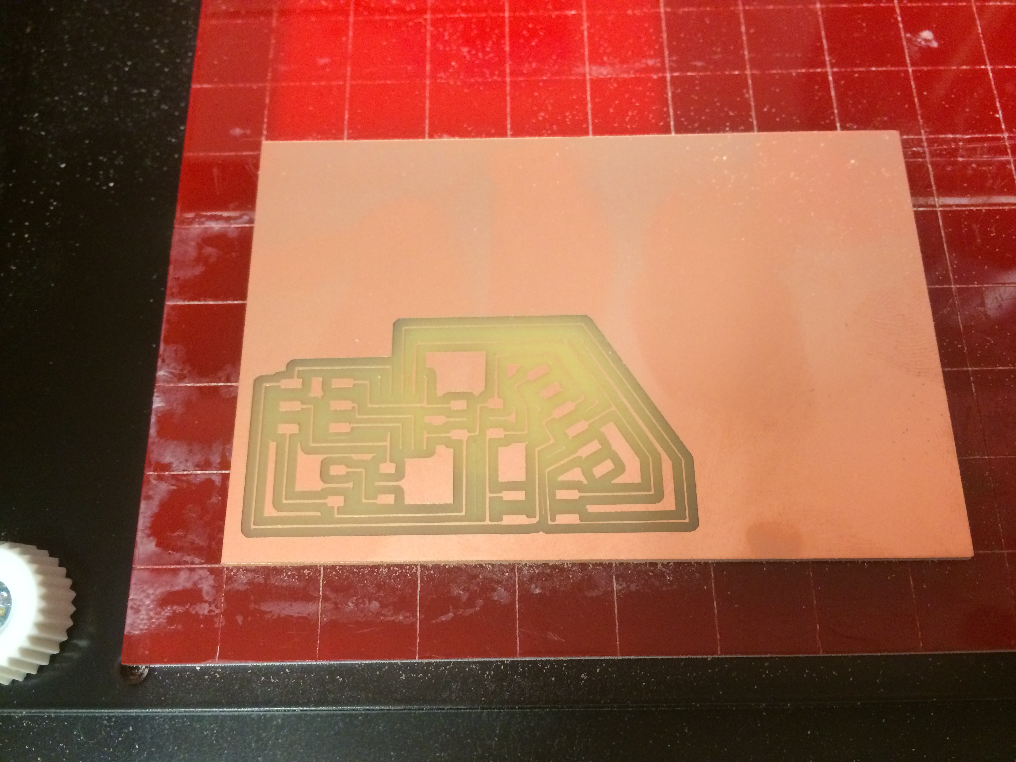
This week's assignment was the most difficult yet, as I was riddled with software issues. I tackled all of the programming and software issues with some pre-designed boards. I simply downloaded the board files from the Fab Academy site (the ones under "serial>asynchronous"). I opened the traces in Fab Modules and milled two node boards and one bridge board. I had to change the bit at first because the 1/64th was a bit dull.
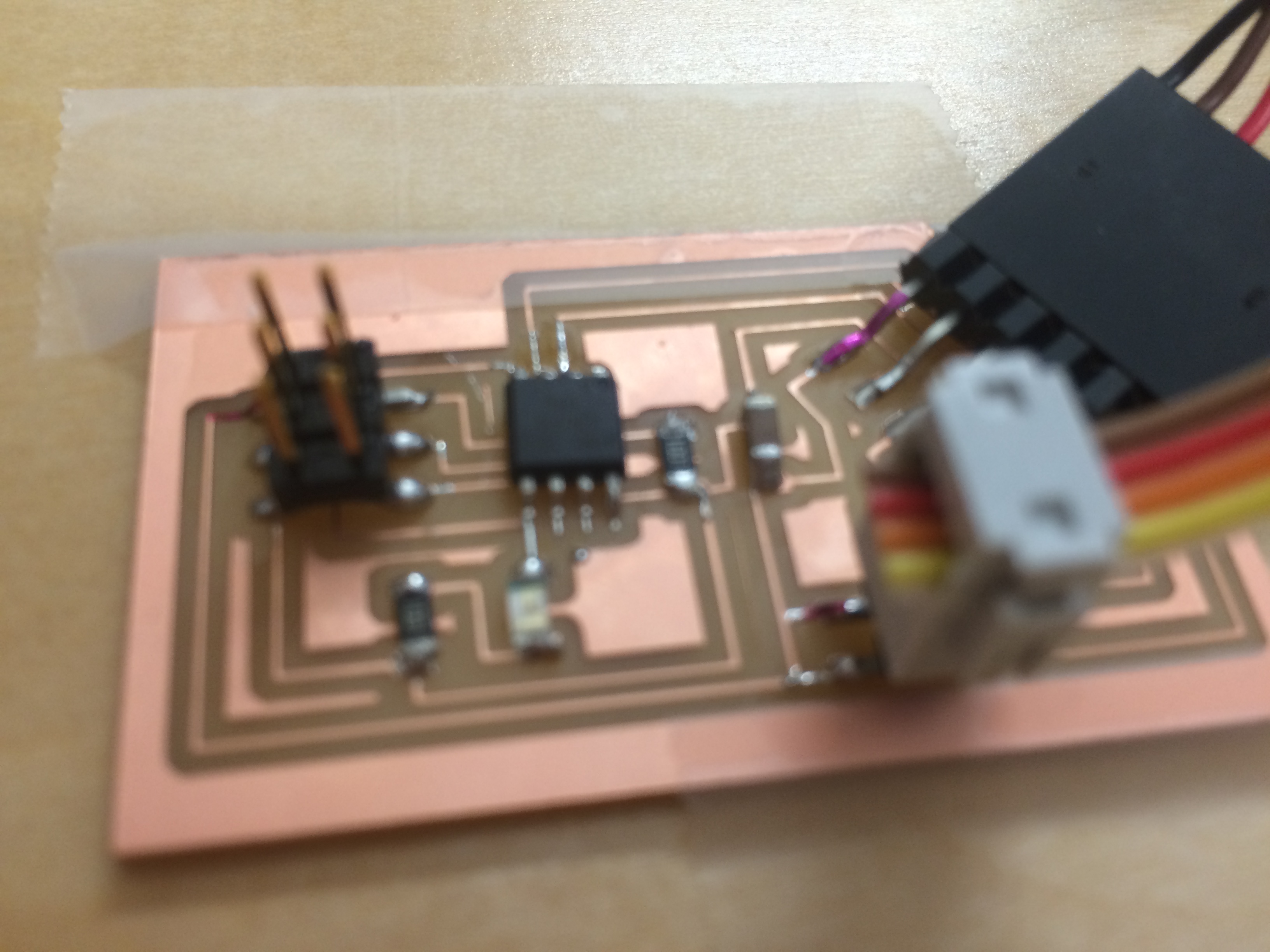
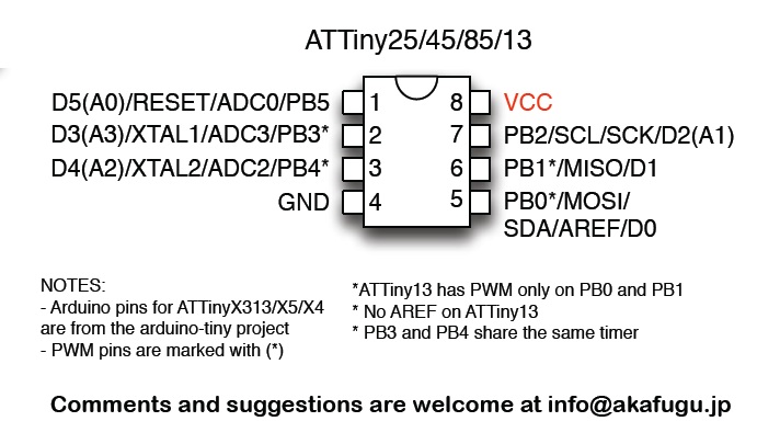
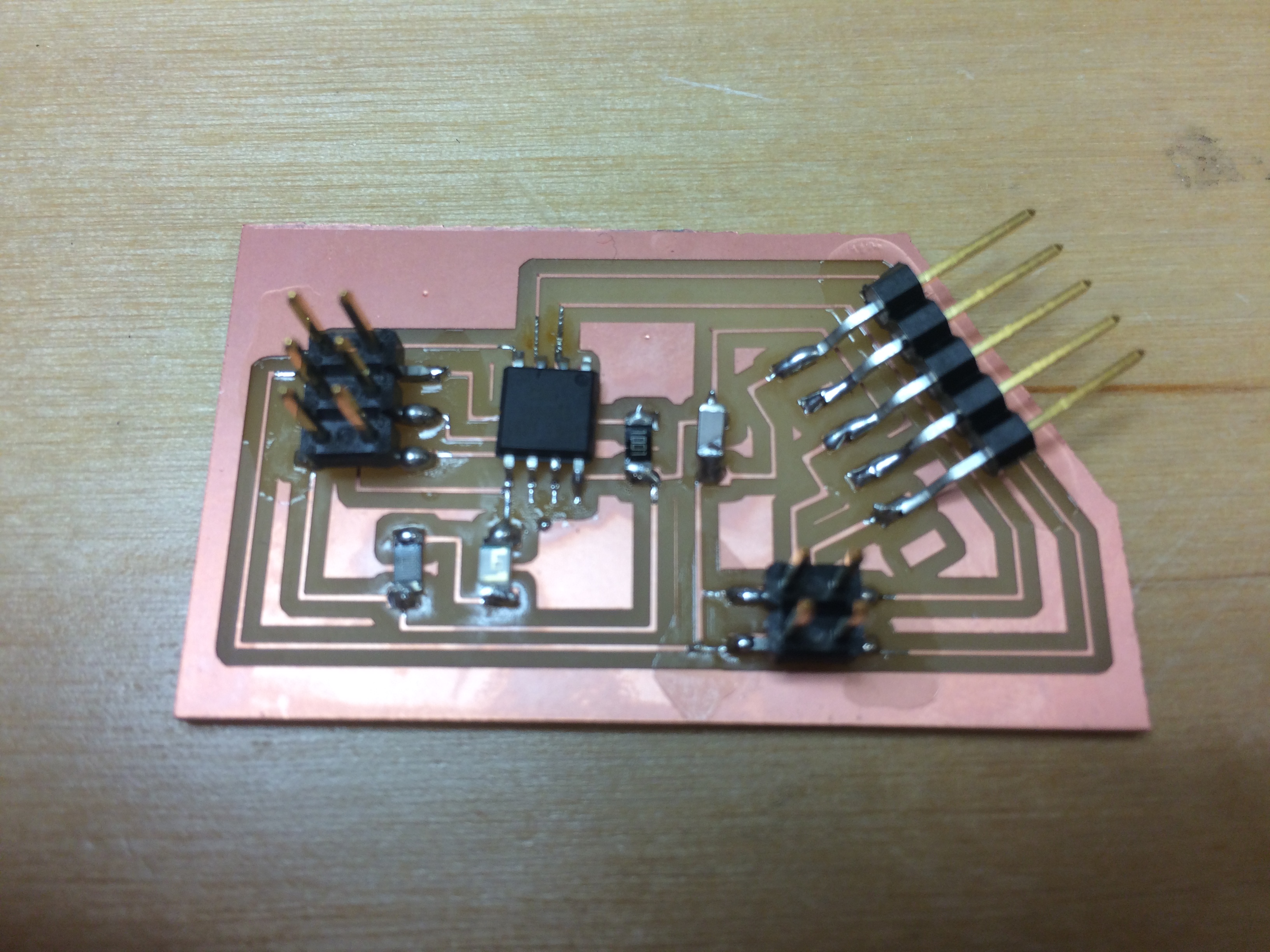
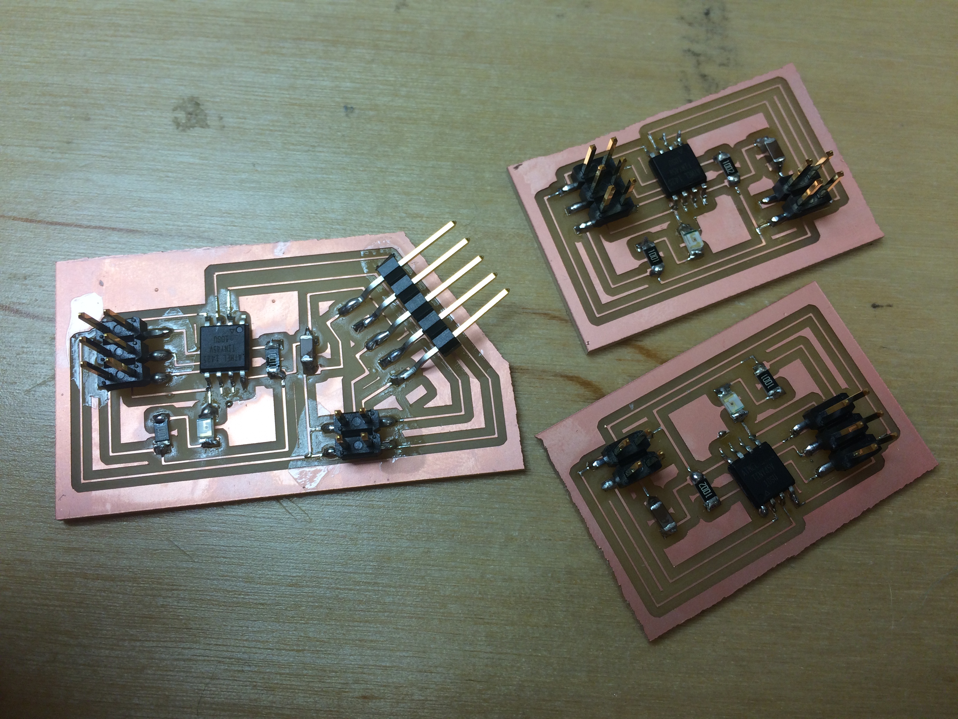
Once I finished milling the boards, I cut them apart and then stuffed them, using an ATTiny45 as the processor chip. I was careful to align the pins correctly on the board, and I used the pinout diagram which I found online to help me.
I was feeling pretty good at this point, and I was ready to tackle flashing the boards and assigning them each a node. I downloaded the code found on the Fab Academy site and I started a new sketch in Arduino. Here is where the problems began. I was using a different computer than I had used for my Hello Board assignment, so things weren't quite the same in this Arduino...
I was using Arduino 1.6.9, and when I tried to compile the the file I got the following error:
recipe.preproc.macros pattern is missing
Error compiling for board ATtiny
So, after some hunting on the internet, I tried downloading and installing Arduino version 1.6.8. Then, I installed the ATTiny board files in the hardware folder and tried to compile again. This time my error message was:
Next error exec: "-w" executable file not found in %PATH%
I had no idea what this meant, but the wise internet people seemed to be telling me that the problem was with my ATTiny board files. So, I deleted the attiny file in the hardware folder, redownloaded it, and then re-installed it in the same exact spot. This time my error message read:
Could not find USBTiny device
I tried a number of different ways of installing these board files into Arduino. I added a folder "Sketchbook> hardware," I tried just in "Sketchbook," I tried moving them out of their file folder directly into any of the above file folders, but I was having no luck.
I got pretty sick of these ATTiny board files by this time, so I found a tutorial on how to easily install 3rd party board software through the boards manager URL. This was a handy tutorial, and it worked very well and quickly with Arduino 1.6.8. So this time my error code changed again:
Compiling code error: PB4 was not declared in this scope
About an hour was spent on this error, I tried changing all the PB4 references in the code to PORTB4, but that didn't work either. The internet peopl were of little use to me for this one, and, throwing my hands up in dismay, I moved over to an Ubuntu computer.
Ubuntu has this neat Software Center application that is designed to make installing programs easy. Or not. It did not make my installation easy. So instead, I followed this tutorial for Arduino 1.6.9. This was simple enough, and it worked.
Then I had to install the ATTiny board files, which I tried to do by following these steps:
After getting frustrated by all this, I eventually abandoned Arduino altogether and moved onto terminal.
I then went back to the Fab Academy site and re-downloaded the original Neil files without renaming them or anything. Then, in terminal, I navigated to the folder where those files were saved and I typed:
make -f hello.bus.45.make
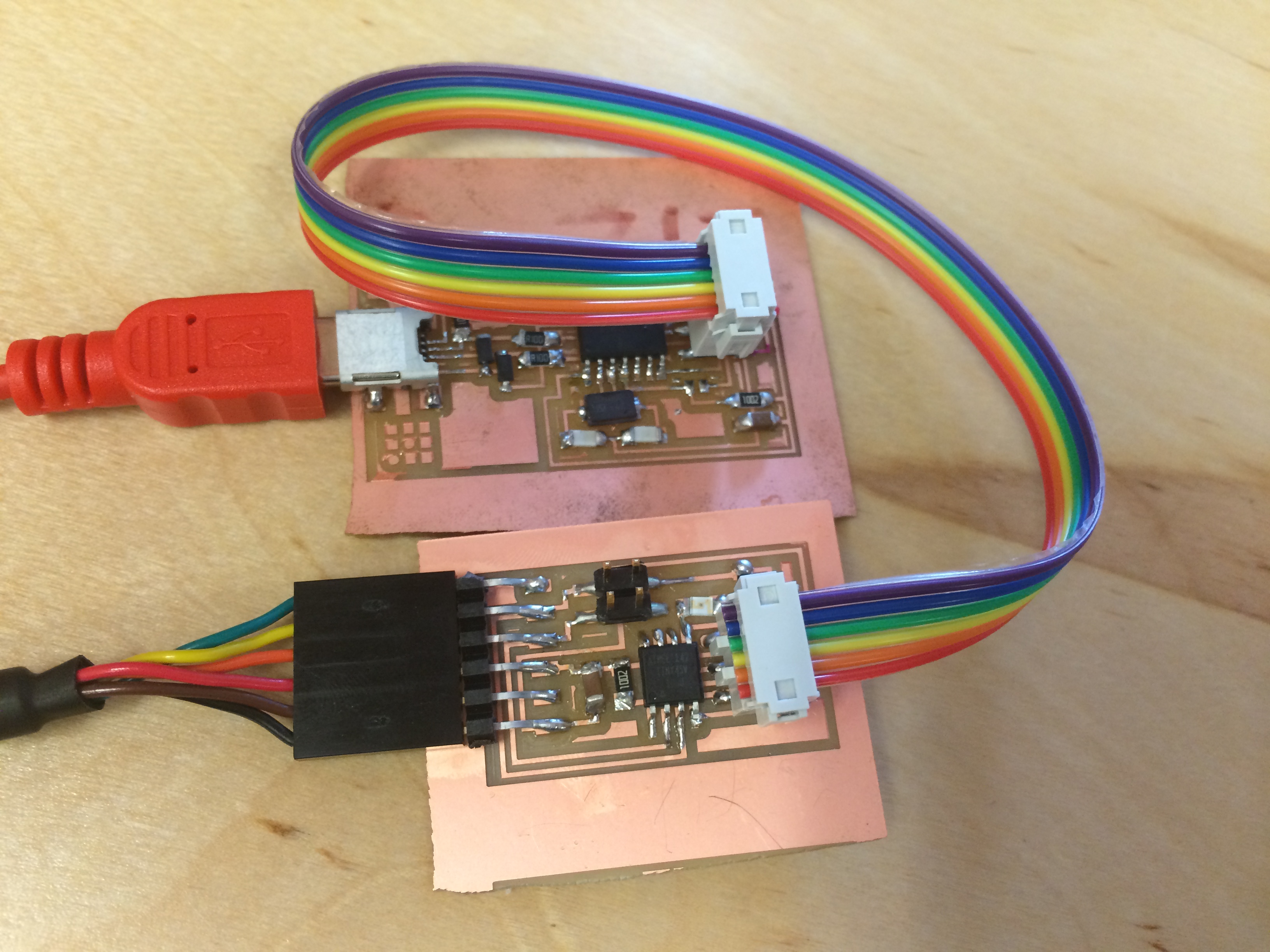
Then, low and behold, the hex file appeared in my folder! So then I connected the FabISP to the computer with the USB cable, I attached the bridge board to the Fab ISP with the 6 ribbon cable, and then I attached the bridge board to the computer using the FTDI cable.
Next, in terminal, I made sure I was in the right folder and then I typed:
Sudo make -f hello.bus.45.make program-usbtiny
This should flashed my bridge board as Node 0. Then the next thing I needed to do was change the code in the original file and do it all over again for the node boards.
Here is what I did
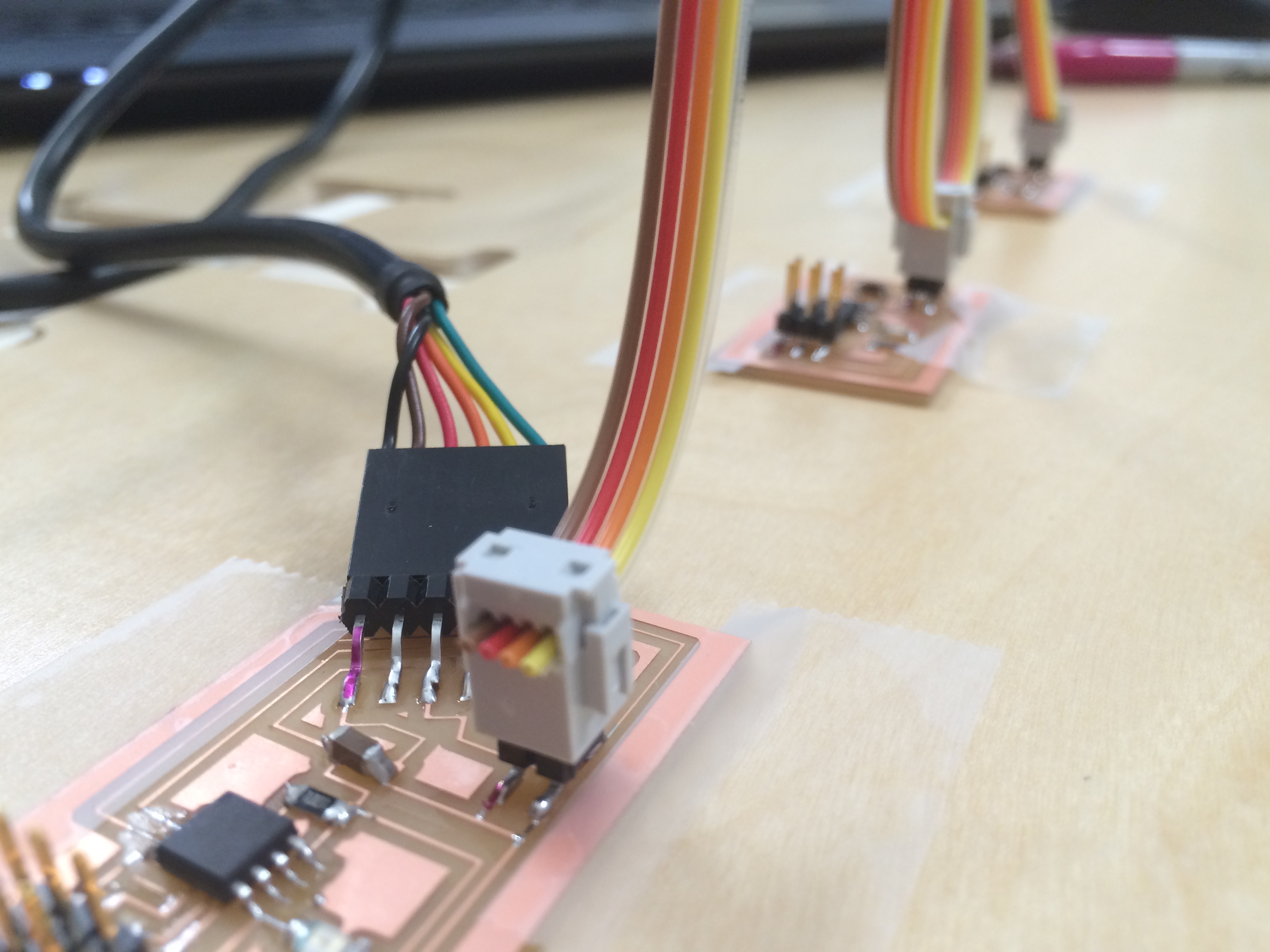
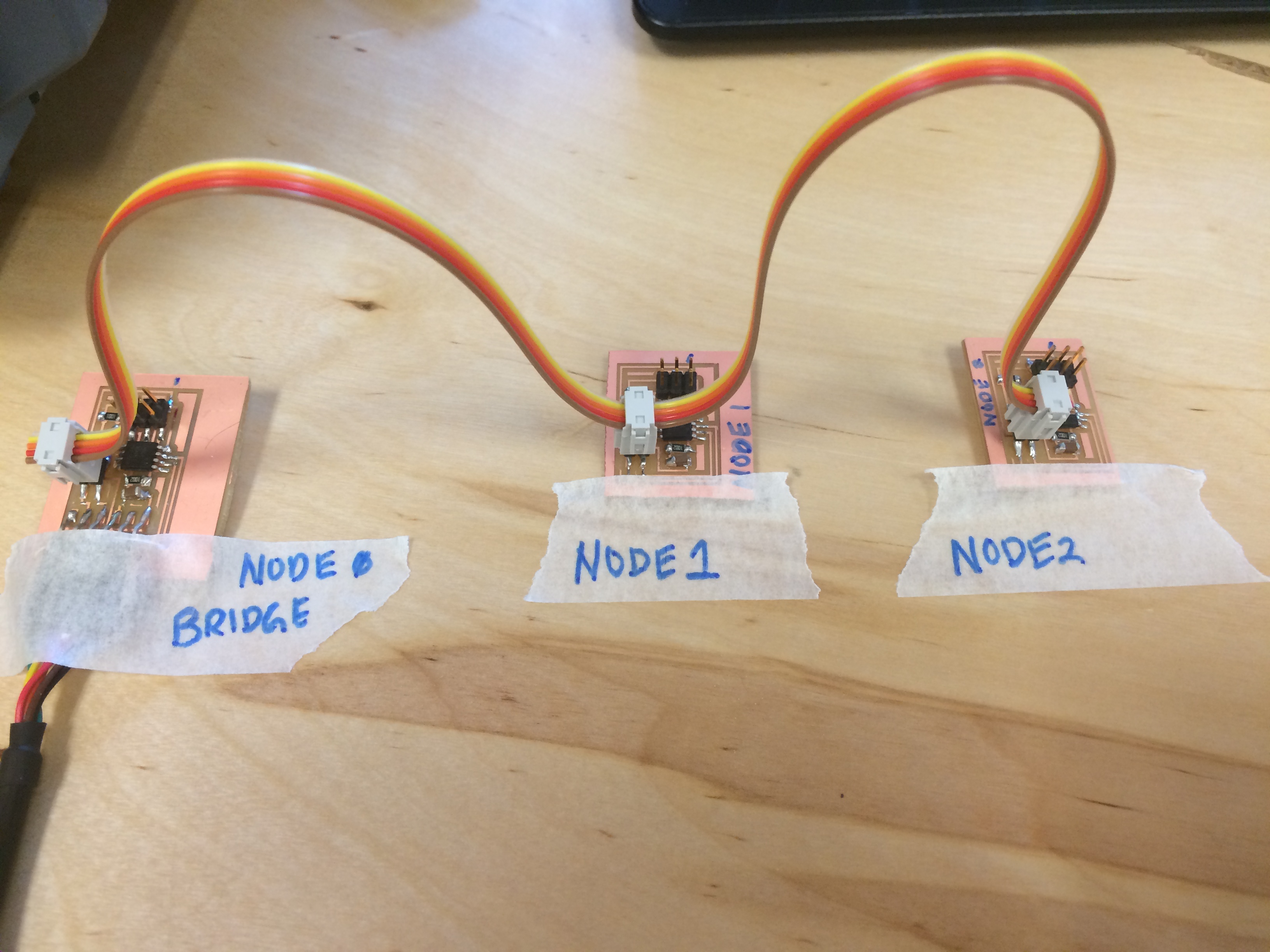
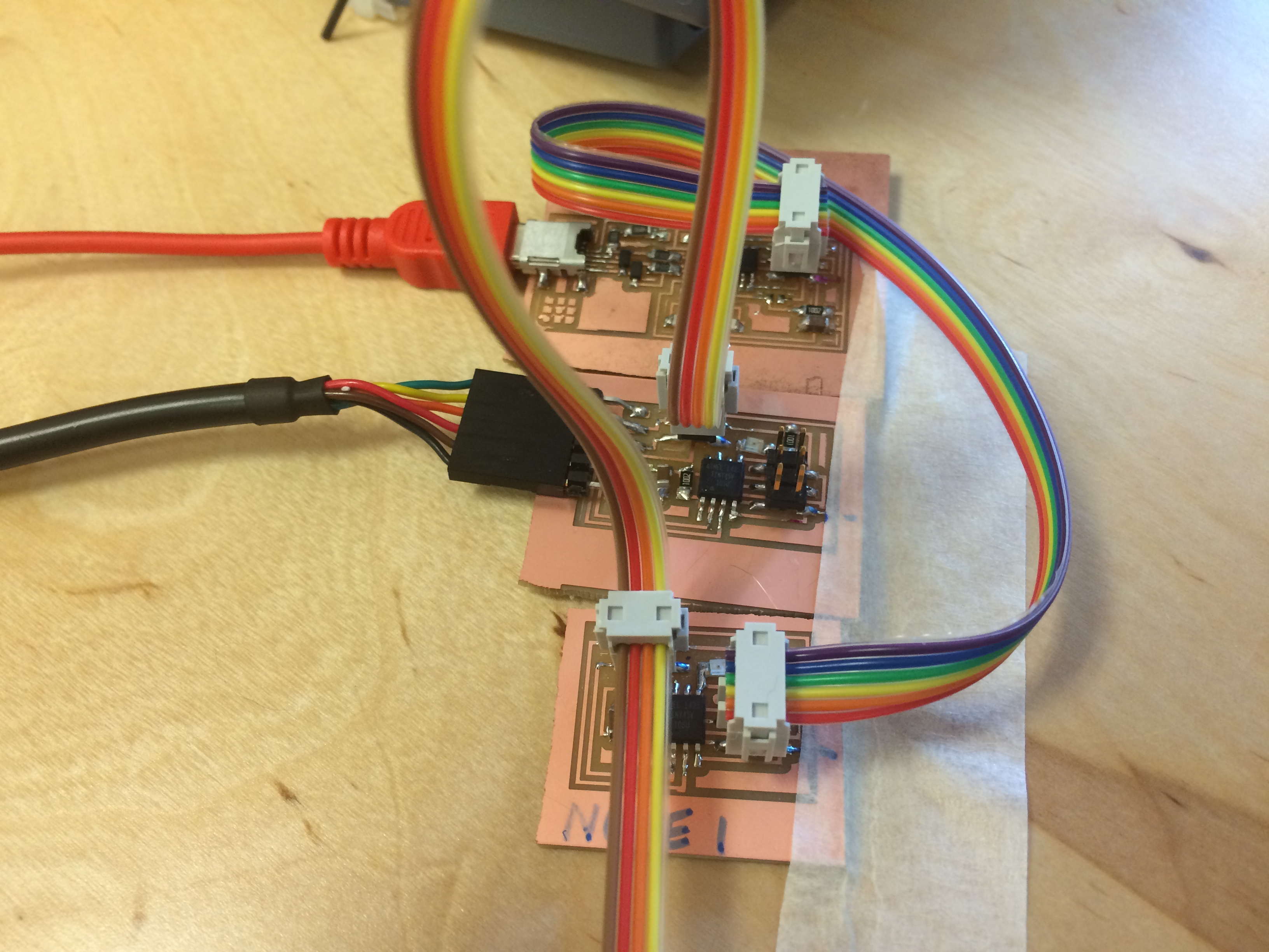
In order to flash the node, I left my bridge board attached to teh FTDI cable, I used my 4 cable ribbon wire to connect the bridge and node (being careful to match pins- in order to make this easier, I marked the GND pins on all the boards with a sharpie dot.). I also connected the 6 cable ribbon wire from the Fab ISP to the node board. Here is how I hooked up my Node 1 board:
Then I repeated the steps above and flashed Node 2.
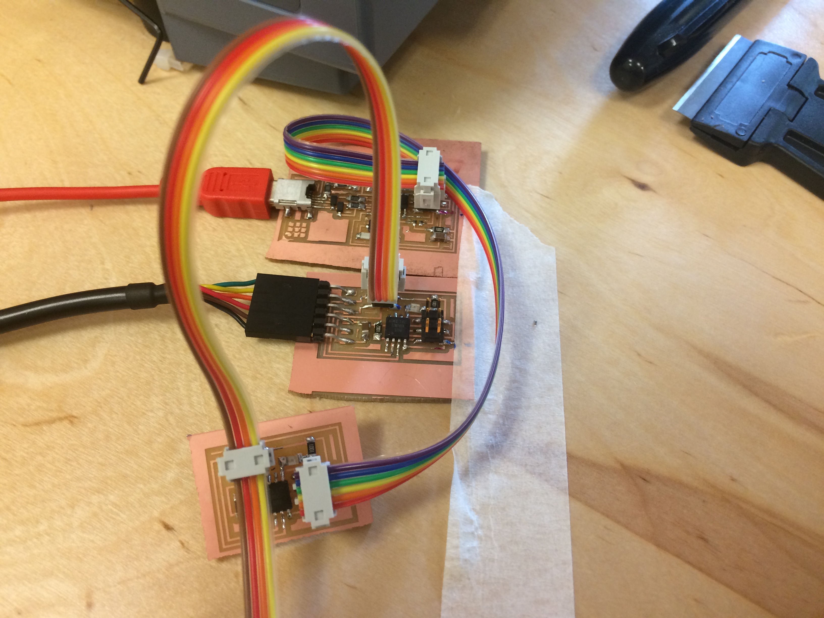
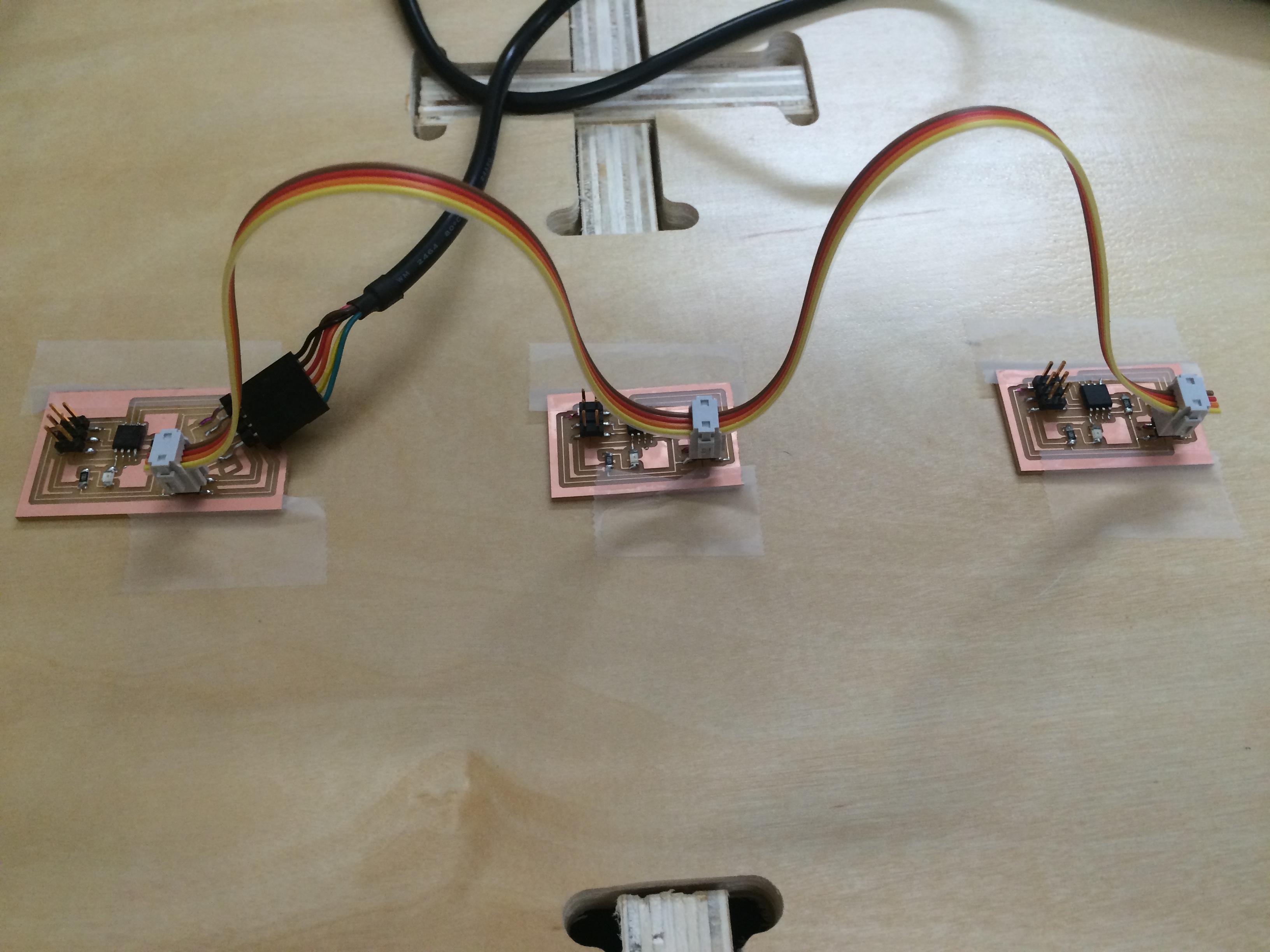
Then I unconnected my ISP and hooked up my bridge board and my two nodes, again being careful about the TX and RX on everything. My bridge board stayed connected to my computer with the FTDI cable.
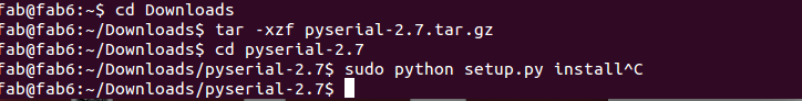
Next I needed to communicate with my network using the terminal window and a serial monitor, which meant, according to the internet people, I had to install lots of things! The first of which is called py serial which I downloaded from this site. Here are the steps I used to install this program:
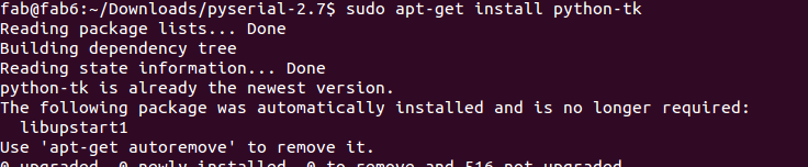
I also needed to install a library called tkter. Here is how I did that using terminal
Then I downloaded a file called term.py and I navigated to the folder containing it in terminal. This was supposed to open up the communication between terminal and the serial monitor which I had installed. But, before that could work, I had to find out what my board was called...
So I typed
ls /dev
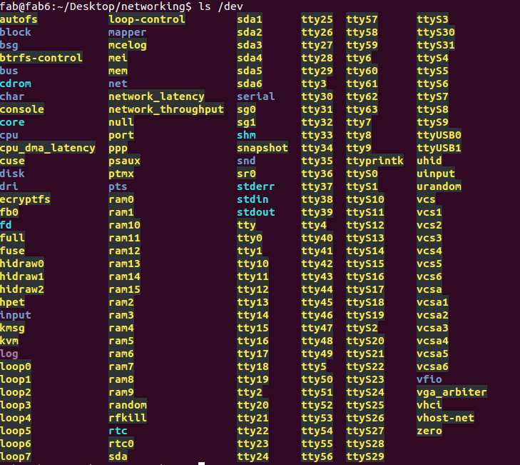
Apparently I was supposed to figure out which board was mine through this gigantic list… this was disheartening to say the least. I didn’t even know where to begin.
Ok, when I did figure out where to begin, it was even more frustrating. Once I figured out which is mine I would type into terminal:
python term.py /dev/___________ 9600
The only thing I could think of doing at this point was mind numbing work, but I started it anyway. I worked my way systematically through all of the names on that list, plugging them into that line of code, "python term.py /dev/___________ 9600." I started with tty0. This took a long time, but when I eventually got to ttyUSB0, a new serial monitor popped up! I couldn't believe my eyes, after about 20 minutes of straight typing into terminal, there was suddenly a new window!
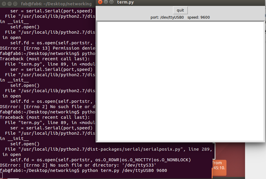
The next problem was, however, that I couldn't figure out how to light the nodes through terminal. My terminal window was stuck and there was no way to input through the serial monitor.
SOOOO… I took my whole rig back to the Windows computer running Arduino IDE 1.6.8, and I opened up a serial monitor. I typed the number 1 in and then all three boards flashed once but Node 1 flashed twice! It was a Saturday night miracle! I tried typing in 2 and it worked the same, all boards flashed and then node two flashed again (the flashes are so close to one another, but they are distinct.)
I am calling it a success.
Here is the video of the networking project FINALLY working!
Click here to download the code that I used.
Once I had the networking under control, I went back some weeks later and spent time redesigning the boards. I drew both the bridge board and the nodes from scratch in Eagle, based on my original boards which were the hello.bus.45.bridge and the hello.bus.45.node.
Here are the files for my bridge board:
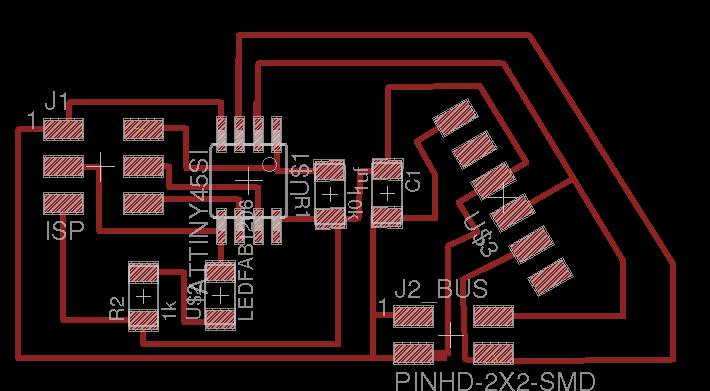
Components in bridge board:
Here are the files for my node boards:
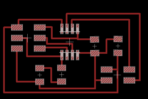
Components in node boards:
After drawing both boards in Eagle, I milled them on the Modela.
The milling was easy, and then I did the stuffing. My soldering skills are improving, if I do say so myself. I even attached the FTDI header at a jaunty angle in order to be easier to plug in and out of the FTDI cable.
Once I had them all stuffed, I carefully marked the ground wire on each jack header to help with plugging in (I used a Sharpie). Then, I grabbed the cable I made originally for this purpose and I began the process of flashing the boards. I went through considerably less rigamarole with the software issues.