Week 9 and Week 11: Mechanical and Machine Design


FAB ARM: The Making


Week 09 : Mechanical Design

Team Members

Introduction

For the Mechanical Design and Machine week, we plan to construct a Robotic arms that moves along a guide rail. The robotic Arm will have 4 degrees of freedom and move about a guide rail. We plan to test the concept of modular design - parts which connect together to make any parts you want all you have to do is change the end effector it can be a 3d printer, a lasercutter, milling machine. The guide rails functionality and robotic arm functionality can be integrated together. The robot should be capable of pick and place light weight objects. Here is the Initial sketch of the Robot that we intend to build.


The Arm is based on existing uArm. It is a miniature 4-axis parallel-mechanism robot arm, modeled after the ABB PalletPack IRB460 indutrial robot arm. It is made up of laser cut acrylic or wood parts, powered by standard RC hobby servos, and controlled by an Arduino-compatible board. The basic design is Arduino-controlled, using 4 servos, with 4 degrees of freedom. Three servos on the base control the main movement of the arm and the last servo on the top moves and rotates the object.

Concept

It is now possible to build automation devices that can be operated under the guidance of a program. Used with special servo-motors, actuators and sensors, the microprocessor has revolutionized automation.

Planning

The group brain stormed on the group project for the week. Some of the ideas that were discussed were
  1. Linear Guide Rails
  2. Wired machinery for pick and place
  3. Mechanism to draw on white boards
  4. 3d printer - http://www.thingiverse.com/thing:28915 or http://www.thingiverse.com/thing:2149685 or http://www.thingiverse.com/thing:1058861
  5. Sand Sculpting Machine: http://googleweblight.com/i?u=http://www.thisiscolossal.com/2015/06/bruce-shapiros-mesmerizing-kinetic-sand-drawing-machines/&grqid=KirB5JTT&hl=en-IN
  6. Foam Milling / cutting https://www.youtube.com/watch?v=cKRb-X4cwSM
  7. CNC Desktop Coil Winding Machine
Finally, we decided to move ahead with combining two of our proposals - both the arm and the linear guide rail design so it can pick and place or move from one place to other.
Next we decided to check the availability of the parts. Check out the local vendors and made sure that either the parts are available to buy or can be made in Fab lab. Next we decided to task with parallel design, development and documentation. we reused available designs. There was a discussion regarding the possibility of additional complexity by scaling the robotic arms. However, we decided against it as this would call for additional analysis in terms of the changes in moments, forces, static and dynamic stability. The complexity we planned to add is the integration of functionality of two independant machines - robotic arm and the guide rail. Reference : Scaling Law of Robotics
Each individual in the group was allocated certain tasks. Following was the task allocation.
Task Allocation
NameTasks
Renjith M s Load Testing and Arduino Programming, calibration and electrical configuration
Syedjunaid AhmedEnd Effector design,Final Assembly of FAB ARM and Arduino Programming along with python GUI using Kivy
Ganadev PrajapathyEnd Effector Design, assembly and Gestalt and Arduino Programming along with python GUI using Kivy
Jithesh GopalDocumentation + guide rail parts and assembly + load Testing
Rahul S rajanFab Arm Parts and assembly, Guide Rail design and fabrication, Design and fabrication of fab arm stepper base,
Sachin SalimGuide Rail Assembly
Ajith Kumar m gSpacers and assembly of parts, Arduino Programming, calibration and electrical configuration, Gestalt Connector
Sreejith MohananProof of Concept, Initial Design, End Effector Design and Fabrication
Jim J seelanFab Arm Parts and assembly, Guide Rail Design, Final Presentation

Design

FAB ARM design

we started of with a sketch for the FAB Arm assembly. We brain stormed on design, manufacturability and ease of assembly of parts.


we conducted a few prototypings with cardboard using laser cutting machines. And the parts were assembled. Here is a crude assembly in that we made.


Design of the Linear guide rails

We designed the linear guide rail using Fusion. Here is the link of design files.


The guide rail needs to contraint the motion of the arm in the linear guide way. We thought of a rack and pinion mechanism and roller bearing mechanism in order to reduce friction. However, we also did not want to make the system too complicated. The design centered around the design of fabricatable machines by Jens. Here is the modified Rhino File. (todo: add the design files). More information is provided by Rahul S Rajan and Jim Sheelan


Design Considerations

Resolution of the parts
We had to consider what was the range of motion of each parts and what was the resolution of movement required for each elements.
Freedom of movement
The Denavit-Hartenberg (DH) Convention is the accepted method of drawing robot arms in FBD's. There are only two motions a joint could make: translate and rotate. There are only three axes this could happen on: x, y, and z (out of plane). Note that I did not count the DOF on the gripper (otherwise known as the end effector). The gripper is often complex with multiple DOF, so for simplicity it is treated as separate in basic robot arm design. A DOF has its limitations, known as the configuration space. Not all joints can swivel 360 degrees! A joint has some max angle restriction. For example, no human joint can rotate more than about 200 degrees. Limitations could be from wire wrapping, actuator capabilities, servo max angle, etc. The following image gives shows the Free body Diagram of robot we are consutructing. The guide rail is not shown here. The guide rail will add another degree of freedom.


All Joints can rotate only a maximum of 180 degrees because that is the operational range of the servos. Again some rotations are also constrained because of the positioning of the arms. They may interfere with each other. The following labels lists the joints in the robot we are building.
JointType of motionDegree of Freedom
Guide RailLinear1 meter
WaistRotation180 degrees
Guide RailRotation90 Degrees
Guide RailRotation30 Degrees
Ease of Assembly
The parts should be assembled easily. All fasteners should be easily accessible with tools and should not hinder the movement of tools.
Forces and Moments
We decided earlier that the robots would handle only lighter pay load. We decided not to go for heavier stepper motor or heavier and scaled robotic parts. Following image shows the typical force and moment calculations.


Motor Selection
we had to consider the loads and moments so that we could choose appropriate motors - servos and stepper motors. The guide rails had lot of friction between mating parts so we planned to used stepper motor here. For the rest of the joints we used servos. This also depended on the availability of these items in the Fablab. We also decided to go ahead with bipolar stepper motor. With bipolar stepper motors there is only a single winding per phase. The driving circuit needs to be more complicated to reverse the magnetic pole, this is done to reverse the bipolar stepper motor - circuit specialists blogcurrent in the winding. This is done with a H-bridge arrangement, however there are several driver chips that can be purchased to make this a more simple task. The gestalt board comes with an inbuilt stepper motor driver chip. Bipolar stepper motor circuits have the advantage of having just one winding and a low winding resistance. At its power loss limit a bipolar stepper motor will still provide roughly forty percent more torque than a unipolar motor built on the same frame.
Bearing or no bearing - guide rail design


MF84ZZ LF840 Ball Bearing . We need bearings - MF84ZZ LF840 Ball Bearing ??
Weight of elements
This was important as we the ratings of motors were limiting.
Degrees of Freedom
A total of 6 variables are required, for specifying the position and orientation of a rigid body in space. The Mobility formula discussed here can be used for determining the degree of freedom.

Guide rail design

Initial concept was to sandwitch the carriage between guiderail via 4 ball bearing wheels. A bearing on the other axis constrains the lateral axes with the support of gears. We considered using chamfered rails as mentioned in https://github.com/fellesverkstedet/fabricatable-machines.


Availability of sleeves and Spacers

Sleeves and Spacers are not available with vendors and needed to made in lab. Once all the parts were made, we assembled the parts and here is the Final assembly of the robotic arm.

End effector design


Object picker end effector This is the end effector we designed and made to pick and place objects. For more details on the design and assembly visit Sreejith Mohanan's page


Electromagnetic end effector We wound a coil around a core for making temporary magnets to pick and place objects made of magentic material.


Further we also made a pen holder and a make shift broom stick that could be mounted on to the FAB arm as different end effector.

Production

The following parts were cut off craft wood using laser cutting machine. Here are the design files. (add the design files) See photos of Fab Arm parts.


The Sleeves were made in the 3-D printing made from the 3D printing machine.


Assembly

All the parts were assembled.


Load Testing

We controlled the servos using the arduino board. External voltage was supplied to the servos and arduino pins were attached to the input signal connector of the servos.


Here is the entire test setup.


The arduino was programmed using the arduino IDE.

	#include<Servo.h>

Servo l1,l2,l3,l4; // create servo object to control a servo
int angle = 0; // variable to store the servo position
void setup()
{
l1.attach(9); // attached the servo on pin 9 to the servo object
l2.attach(10);
l3.attach(11);
l4.attach(3);
}

void loop()
{


// for the base
  
  int a = 70;
  int a1= 80;
  int a2=60;
  int b = a + 30;
  int b1=a1+40;
  int b2= a2+40;
  //myloop.write(90);
for(angle =a; angle < b; angle += 1) // goes from 0 degrees to 180 degrees
{ // in steps of 1 degree
l1.write(angle); // tell servo to go to position in variable 'angle'
delay(20); // waits 20ms between servo commands
}
for(angle = b1; angle >= a1; angle -= 1) // goes from 180 degrees to 0 degrees
{
l1.write(angle); // move servo in opposite direction
delay(20); // waits 20ms between servo commands
}


for(angle =a; angle < b; angle += 1) // goes from 0 degrees to 180 degrees
{ // in steps of 1 degree
l2.write(angle); // tell servo to go to position in variable 'angle'
delay(20); // waits 20ms between servo commands
}
for(angle = b; angle >= a; angle -= 1) // goes from 180 degrees to 0 degrees
{
l2.write(angle); // move servo in opposite direction
delay(20); // waits 20ms between servo commands
}


for(angle =a; angle < b; angle += 1) // goes from 0 degrees to 180 degrees
{ // in steps of 1 degree
l3.write(angle); // tell servo to go to position in variable 'angle'
delay(20); // waits 20ms between servo commands
}
for(angle = b; angle >= a; angle -= 1) // goes from 180 degrees to 0 degrees
{
l3.write(angle); // move servo in opposite direction
delay(20); // waits 20ms between servo commands
}

for(angle =a; angle < b; angle += 1) // goes from 0 degrees to 180 degrees
{ // in steps of 1 degree
l4.write(angle); // tell servo to go to position in variable 'angle'
delay(20); // waits 20ms between servo commands
}
for(angle = b; angle >= a; angle -= 1) // goes from 180 degrees to 0 degrees
{
l4.write(angle); // move servo in opposite direction
delay(20); // waits 20ms between servo commands
}


}


Here is a video of testing the servo initially with a single arm

With 2 servos engaged

and three servos engaged


Drawing a line repeatedly


Week 11: Machine Design

Making the machine move

In week 9, the assignment was focussed on building the mechanical parts / structure for the machine. In week 11, we had to automate the parts and make the machine move. For the movement we used a combination of servos and stepper motors. We decided to control the servo motors using the arduino board. (Please refer above for description of our investigation to use arduinos to control the servo motor). We wanted to also see how stepper motors could also be used in tandem with the servos. We choose the guide rail as the best place to implement the stepper motor and then use a gestalt to control the stepper motor.

Gestalt board

Gestalt is a control system framework for personal fabrication. This Fab academy page and Starting Gestalt is a good place to get more information regarding Gestalt. We set up the gestalt nodes as mentioned in this site. we were able to connect multiple gestalt nodes each connected to another one in manner of a chain. The first node was connected to usb port of the computer via a USB-RS485 connector, we made in the lab.


Problems encountered in operation of Guide Rail

  1. Friction: The linear guide rail was fabricated in wood. The frictional force was too overwhelming for the stepper motor and it simply would not budge. We tried the following to reduce the frictional forces
    1. Using teflon tapes on the point of contacts to reduce friction
    2. Using Vaseline to reducce the friction
  2. Constraint: The mechanism of rack and pinion was incorrectly constrained. The housing of the pinion was not fit tighly rail (Rack) as to permit free rotation of the rail insided the housing. The pinion was inside the housing. But we found that the pinion was thrown away from each other breaking the contact between the rack and the pinion, once the stepper motor rotated. . Porbably we needed to use some freely rotating bearing to push the pinion agains the rack but at the same time allowing linear motion between the rack and housing.
The board files are Provided here.


Here is the supply source to the board.


The entire connection to one stepper motor is shown below. A provision is given for another gestalt node can be connected to the existing gestalt node.


Here is the code for driving the stepper motor => using Gestalt.
 
	
from kivy.uix.popup import Popup
from kivy.app import App
from kivy.uix.gridlayout import GridLayout
from kivy.uix.label import Label
from kivy.uix.textinput import TextInput
from kivy.uix.button import Button
from kivy.uix.boxlayout import BoxLayout
from kivy.uix.stacklayout import StackLayout
from kivy.uix.slider import Slider
from kivy.config import Config

from kivy.uix.togglebutton import ToggleButton

Config.set('modules', 'serial', '')


# Forked from DFUnitVM Oct 2013
# set portname
# set location of hex file for bootloader
#

#------IMPORTS-------
from pygestalt import nodes
from pygestalt import interfaces
from pygestalt import machines
from pygestalt import functions
from pygestalt.machines import elements
from pygestalt.machines import kinematics
from pygestalt.machines import state
from pygestalt.utilities import notice
from pygestalt.publish import rpc   #remote procedure call dispatcher
import time
import io
import threading
import serial


#------VIRTUAL MACHINE------
class virtualMachine(machines.virtualMachine):
	
	def initInterfaces(self):
		if self.providedInterface: self.fabnet = self.providedInterface     #providedInterface is defined in the virtualMachine class.
		else: self.fabnet = interfaces.gestaltInterface('FABNET', interfaces.serialInterface(baudRate = 115200, interfaceType = 'ftdi', portName = '/dev/tty.usbserial-FT0METG6'))
		
	def initControllers(self):
		self.xAxisNode = nodes.networkedGestaltNode('X Axis', self.fabnet, filename = '086-005a.py', persistence = self.persistence)
		self.xNode = nodes.compoundNode(self.xAxisNode)

	def initCoordinates(self):
		self.position = state.coordinate(['mm'])
	
	def initKinematics(self):
		self.xAxis = elements.elementChain.forward([elements.microstep.forward(4), elements.stepper.forward(1.8), elements.leadscrew.forward(6.096), elements.invert.forward(True)])
		
		self.stageKinematics = kinematics.direct(1) #direct drive on all axes
	
	def initFunctions(self):
		self.move = functions.move(virtualMachine = self, virtualNode = self.xNode, axes = [self.xAxis], kinematics = self.stageKinematics, machinePosition = self.position,planner = 'null')
		self.jog = functions.jog(self.move) #an incremental wrapper for the move function
		pass
		
	def initLast(self):
#       self.machineControl.setMotorCurrents(aCurrent = 0.8, bCurrent = 0.8, cCurrent = 0.8)
#       self.xyzNode.setVelocityRequest(0)  #clear velocity on nodes. Eventually this will be put in the motion planner on initialization to match state.
		pass
	
	def publish(self):
#       self.publisher.addNodes(self.machineControl)
		pass
	
	def getPosition(self):
		return {'position':self.position.future()}
	
	def setPosition(self, position  = [None]):
		self.position.future.set(position)

	def setSpindleSpeed(self, speedFraction):
#       self.machineControl.pwmRequest(speedFraction)
		pass


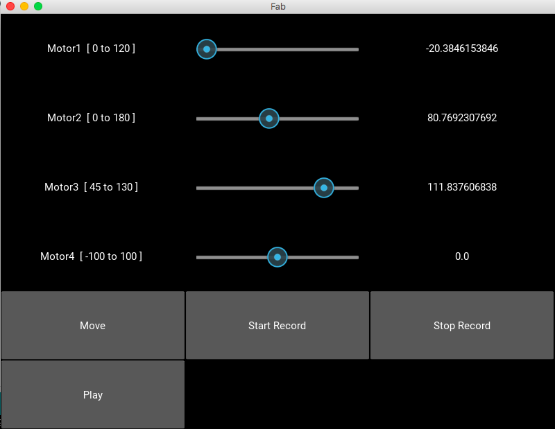
class FabControl(GridLayout):
	def __init__(self, **kwargs):
		super(FabControl, self).__init__(**kwargs)
		self.cols = 3
		self.row = 3

		global serialcom, tempmotor1, tempmotor2, tempmotor3
		tempmotor1 = tempmotor2 = tempmotor3 = 0

		serialcom = serial.Serial()
		serialcom.braudrate = 115200
		serialcom.port = "/dev/tty.usbmodem1421"
		serialcom.open()


		self.add_widget(Label(text='Motor1  [ 100 to 180 ] '))

		self.motor1 = Slider(min=100, max=180, value=100)
		self.motor1.bind(value=self.Motor1Change)
		self.add_widget(self.motor1)

		self.motor1value = Label(text=str(self.motor1.value))
		self.add_widget(self.motor1value)


		self.add_widget(Label(text='Motor2  [ 0 to 180 ] '))

		self.motor2 = Slider(min=0, max=180, value=0)
		self.motor2.bind(value=self.Motor2Change)
		self.add_widget(self.motor2)

		self.motor2value = Label(text=str(self.motor2.value))
		self.add_widget(self.motor2value)


		self.add_widget(Label(text='Motor3  [ 45 to 130 ] '))

		self.motor3 = Slider(min=45, max=130, value=45)
		self.motor3.bind(value=self.Motor3Change)
		self.add_widget(self.motor3)

		self.motor3value = Label(text=str(self.motor3.value))
		self.add_widget(self.motor3value)


		self.add_widget(Label(text='Motor4  [ -100 to 100 ] '))

		self.motor4 = Slider(min=-100, max=100, value=0)
		self.motor4.bind(value=self.Motor4Change)
		self.add_widget(self.motor4)

		self.motor4value = Label(text=str(self.motor4.value))
		self.add_widget(self.motor4value)


		self.move = Button(text="Move")
		self.add_widget(self.move)
		self.move.bind(on_press=self.initiatemove)

		# btn1 = ToggleButton(text='Male', group='sex',)
		self.btn = ToggleButton(text='Record', state='normal')
		self.add_widget(self.btn)
		# btn3 = ToggleButton(text='Mixed', group='sex')

		# self.startrec = Button(text="Start Record")
		# self.add_widget(self.startrec)

		# self.stoprec = Button(text="Stop Record")
		# self.add_widget(self.stoprec)

		self.play = Button(text="Play")
		self.add_widget(self.play)

	def Motor4Change(self, instance, value):
		self.motor4value.text = str(value)

	def Motor1Change(self, instance, value):
		self.motor1value.text = str(value)

	def Motor2Change(self, instance, value):
		self.motor2value.text = str(value)

	def Motor3Change(self, instance, value):
		self.motor3value.text = str(value)

	def initiatemove(self,instance):
		# time.sleep(5)
		threading.Thread(target=self.movemotor4).start()
		threading.Thread(target=self.movemotor1).start()
		threading.Thread(target=self.movemotor2).start()
		threading.Thread(target=self.movemotor3).start()

	def movemotor4(self):
		print "movemotor4 called"
		global stage
		# print stage
		# print self.motor4.value
		# print self.motor1.value
		# print self.motor2.value
		# print self.motor3.value

		# 
		movemotor4 = int(self.motor4.value)

		supercoords = [[movemotor4], [0]]

		for coords in supercoords:
			stage.move(coords, 0)
			status = stage.xAxisNode.spinStatusRequest()
			while status['stepsRemaining'] > 0:
				time.sleep(0.001)
				status = stage.xAxisNode.spinStatusRequest()


	# ser = serial.Serial()
	# ser.braudrate = 115200
	# ser.port = "/dev/tty.usbmodem1411"
	# ser.open()
	def movemotor1(self):
		print "movemotor1called"
		global serialcom, tempmotor1
		movemotor1 = self.motor1.value - tempmotor1
		tempmotor1 = self.motor1.value
		print movemotor1
		if serialcom.isOpen():
			print("serialcomial is open!")
			if movemotor1 > 0:
				for i in range(int(movemotor1) / 5):
					print 'sending a'
					time.sleep(500)
					serialcom.write('a\n')
					print serialcom.readline()
			else:
				for i in range(abs(int(movemotor1) / 5)):
					serialcom.write('na\n')
					time.sleep(500)
					print serialcom.readline()

		# serialcom.close()


	def movemotor2(self):
		print "movemotor2called"
		global serialcom, tempmotor2
		movemotor2 = self.motor2.value - tempmotor2
		tempmotor2 = self.motor2.value
		print movemotor2
		if serialcom.isOpen():
			print("serialcomial is open!")
			# serialcom.write('a\n')
			if movemotor2 > 0:
				for i in range(int(movemotor2)):
					print 'sending b'
					serialcom.write('b\n')
					time.sleep(500)
					# print serialcom.read()
					print serialcom.readline()
			else:
				for i in range(abs(int(movemotor2))):
					serialcom.write('nb\n')
					time.sleep(500)
					# print serialcom.read()
					print serialcom.readline()


	def movemotor3(self):
		print "movemotor3called"
		global serialcom, tempmotor3
		movemotor3 = self.motor3.value - tempmotor3
		tempmotor3 = self.motor3.value
		print movemotor3
		if serialcom.isOpen():
			print("serialcomial is open!")
			# serialcom.write('a\n')
			if movemotor3 > 0:
				for i in range(int(movemotor3)):
					print 'sending c'
					serialcom.write('c\n')
					time.sleep(500)
					# print serialcom.read()
					print serialcom.readline()
			else:
				for i in range(abs(int(movemotor3))):
					serialcom.write('nc\n')
					time.sleep(500)
					# print serialcom.read()
					print serialcom.readline()


class FabApp(App):
	def build(self):
		global stage
		stage = virtualMachine()
		# print dir(stage.xNode)
		#stage.xNode.loadProgram('../../../086-005/086-005a.hex')
		#stage.xNode.setMotorCurrent(1)

		stage.xNode.setVelocityRequest(8)   
		
		return FabControl()


if __name__ == '__main__':
	FabApp().run()


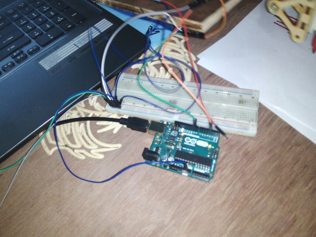
Here is the code for driving the servo motors

	//add servo library
#include <Servo.h>

//define our servos
Servo servo1;
Servo servo2;
Servo servo3;
//Servo servo4;

//define our potentiometers
//int pot1 = A0;
//int pot2 = A1;
//int pot3 = A2;
//int pot4 = A3;

//variable to read the values from the analog pin (potentiometers)
int valPot1 = 100;
int valPot2 = 0;
int valPot3 = 45;
//int valPot4;
char inByte;

void setup()
{ Serial.begin(9600);
  //attaches our servos on pins PWM 3-5-6-9 to the servos
  servo1.attach(9);
  servo1.write(valPot1);  //define servo1 start position
  
  servo2.attach(10);
  servo2.write(valPot2); //define servo2 start position
  
  servo3.attach(11);
  servo3.write(valPot3); //define servo3 start position
  
//  servo4.attach(6);
//  servo4.write(70); //define servo4 start position
}

void loop()
{
  //reads the value of potentiometers (value between 0 and 1023)


//  valPot1 = analogRead(pot1);
//  valPot1 = map (valPot1, 0, 1023, 100, 180); //scale it to use it with the servo (value between 0 and 180)
//  servo1.write(valPot1); //set the servo position according to the scaled value
////-------------------------------------------------------------
//  valPot2 = analogRead(pot2);
//  valPot2 = map (valPot2, 0, 1023, 0, 180);
//  servo2.write(valPot2);
// //-----------------------------------------------------------------
//  valPot3 = analogRead(pot3);
//  valPot3 = map (valPot3, 0, 1023, 45, 130);
//  servo3.write(valPot3);
//
//  valPot4 = analogRead(pot4);
//  valPot4 = map (valPot4, 0, 1023, 70, 150);
//  servo4.write(valPot4);
 if (Serial.available())
 {
    inByte = Serial.read();
    switch (inByte) {
      case 'n':
        delay(200);
        inByte = Serial.read();
        switch (inByte) {
          case 'a':
            Serial.print("-a");
            valPot1 -= 5;
            servo1.write(valPot1);
            Serial.println("  ");
            break;
          case 'b':
            Serial.print("-b");
            valPot2 -= 5;
            servo2.write(valPot2);
            Serial.println("  ");
            break;
          case 'c':
            Serial.print("-c");
            valPot3 -= 5;
            servo3.write(valPot3);
            Serial.println("  ");
            break;
          case 'n':
            Serial.print("n");
            Serial.println("  ");
            break;
          case '\n':
            break;
          default:
            Serial.print("Wrong n Input");
            Serial.println("  ");
            break;
        }
        break;
      case 'a':
        Serial.print("a");
        valPot1 += 5;
        servo1.write(valPot1);
        Serial.println("  ");
        break;
      case 'b':
        Serial.print("b");
        valPot2 += 5;
        servo2.write(valPot2);
        Serial.println("  ");
        break;
      case 'c':
        Serial.print("c");
        valPot3 += 5;
        servo3.write(valPot3);
        Serial.println("  ");
        break;
      case 's':
        Serial.print(byte(valPot1));
        Serial.print("  ");
        Serial.print(byte(valPot2));
        Serial.print("  ");
        Serial.print(byte(valPot3));
        Serial.println("  ");
        break;
      case '\n':
        break;
      default:
        Serial.print("Wrong Input");
        Serial.println("  ");
  }
}
}

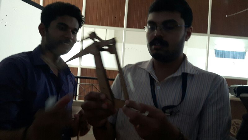
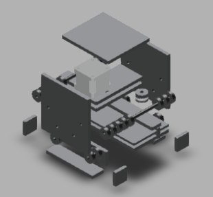
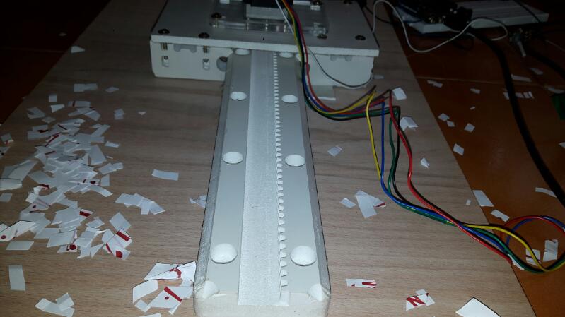
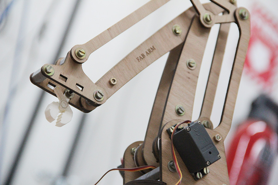
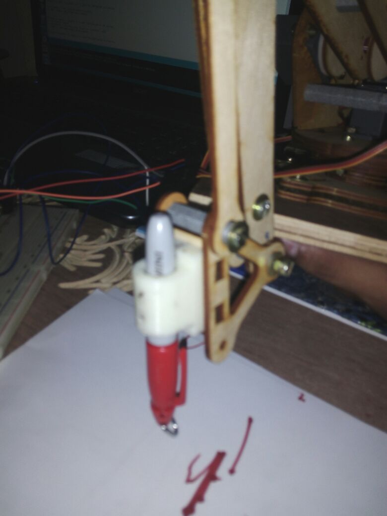
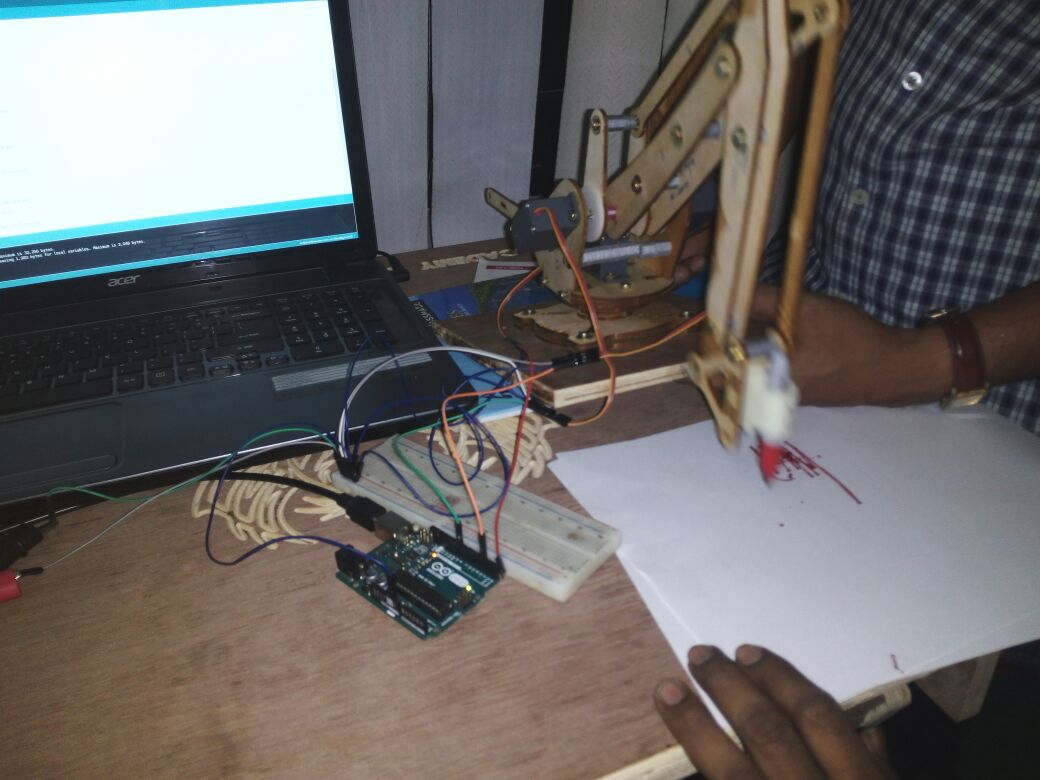
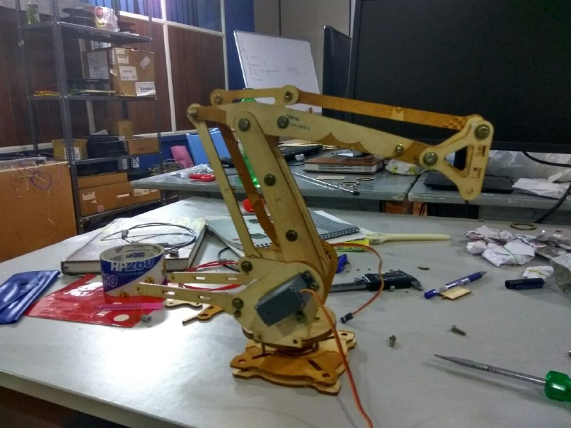
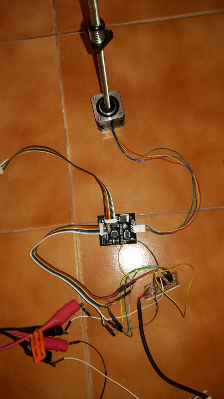
Finally we can see the entire machine is in motion. The end effector we have used here is a broom stick (miniature ofcourse!!). And here it is in action !!!! 
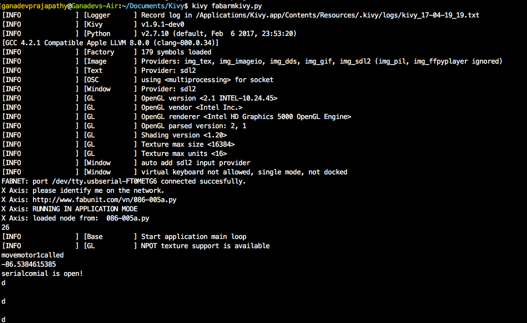
To run the python kivy program, kivy fabarmkivy.py


Screenshot of the UI,


It took us a while because it wasn't quite working as intended by the code, it was too jittery and random, sometimes it moves correct sometimes doesn't


Finally figure it was due to some loose connections and we replaced the servos as well during debugging,

Controlling via GUI


Front View Side View


Pick and Place end Effector Pen End Effector

References

Part List

Mechanical Parts
Item Number Item Name Item Description Qty Make/Buy
1 Laser Printing Wooden Board 4 Buy
1 Shop Bot Wooden Board 12" 1 Buy
Components
Item Number Item Name Item Description Qty Make/Buy
1 For Basic FAB-ARM 1 Screw M4-8 16 Buy
Screw M4-16 11 Buy
2 For Basic FAB-ARM 2 Screw M4-12 12 Buy
Screw M4-22 1 Buy
3 For Basic FAB-ARM 3 Screw M4-14 4 Buy
Screw M4-25 8 Buy
4 For Basic FAB-ARM 4 Screw M2-10 8 Buy
Tap Screw M2-10 8 Buy
Tap Screw M2-12 4 Buy
5 For Basic FAB-ARM 5 Nut M2 2 Buy
Nut M4 24 Buy
Lock Nut M4 4 Buy
6 For Basic FAB-ARM 6 Metal Spacer 4x10x1 5 Buy
Shaft Sleeve M4-7 8 Make
7 For Basic FAB-ARM 7 Brass Stand-offs M4-10 4 Buy
Brass Stand-offs M4-15 1 Buy
Brass Stand-offs M4-22 4 Buy
Brass Stand-offs M4-55 2 Buy
Brass Stand-offs M4-65 1 Buy
Aluminum Alloy Rod 8-45 1 Buy
8 For Basic FAB-ARM 8 Thin-walled Bearing 61807 1 Buy
Flange Bearing MF84ZZ 12 Buy
Flange Shaft Sleeve 12 Make
3 For Basic FAB-ARM 9 Suction Cup 45-M5 4 Buy
Rivet M5-10 3 Buy
10 For Basic FAB-ARM 9 Screw M4-28 3 Buy
Electronic Parts
Item Number Item Name Item Description Qty Make/Buy
1 Servos servos 3 Buy
2 Stepper Motors Stepper Motors 1 Buy
3 Gestalt Board Gestalt Board 1 Buy
4 Arduino Board Arduino Board 1 Buy
5 Blank PCB Blank PCB 1 Buy
6 USB cables USB cables 1 Buy
7 Power supply Power supply 1 Buy
8 Power supply cables Power supply cables 1 Buy