Mechanical Design and Machine Design
The Mechanical Design and Machine design is a two weeks activity. in the first week, we need to make a machine, including the end effector, build the passive parts and operate it manually. And in the second week, we need to automate our machine. And we need Document the group project and our individual contribution. To maintain the continuity of the tasks, both the weeks documents are combined together in this page.
Mechanical Design - Building the physical Fabarm
We sat for a meeting and discussed about machines that could be possible to be made in our lab. 3D printers, PCB millers, foam cutters and robotic arms where discussed. Finally, we decided to make a Robotic Arm, and for novelty we planned to construct a Robotic arm that moves along a guide rail.
This intended robotic Arm on rails will have 4 degrees of freedom, (3 dof as typical robotic arms and the 4th one by the movement on a guide rail). We also thought to make the design of this as moduar, so that multiple parts could connect together easily. So that to change configurations all we want to do is change the end effector it could then become a 3d printer, or a lasercutter, or a milling machine etc. And as the guide rails functionality and the robotic arm functionality are integrated together, the robot arm could be capable of moving on a linear axis thus increasing the reach of the arm. This robot arm will also be capable of pick and place light weight objects.
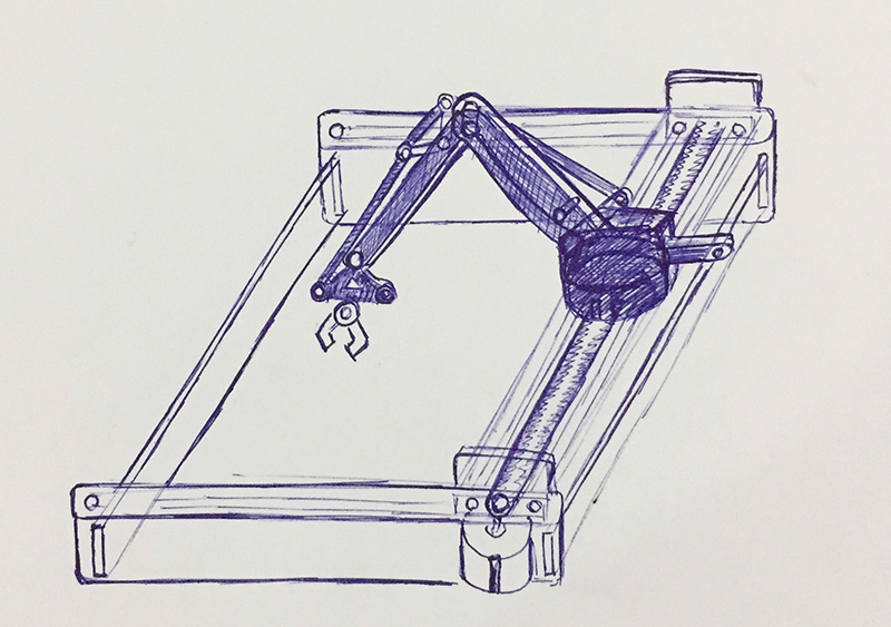
We discussed various possible configurations for the Arm, and finaly decided to base it on the UArm. UArm is a miniature 4-axis parallel-mechanism robot arm, modeled after the ABB PalletPack IRB460 indutrial robot arm. It is made up of laser cut acrylic or wood parts, powered by standard RC hobby servos, and controlled by an Arduino-compatible board. The basic design is Arduino-controlled, using 4 servos, with 4 degrees of freedom. Three servos on the base control the main movement of the arm and the last servo on the top moves and rotates the object. In our design we planed to discard the last servo that rotates the object. And thus having the 3 degrees of freedom, if we consider just the arm, and 4 degrees of freedom if we also consider the rails.
The Plan and the team
After we finalized the project, we next sat together and did the work planning. Being from the mechanical Engineering background myself and Rahul were tasked with the design of various parts including the rails. The details of the plan and the team member details are available on our group page link. [Fab Arm Group Documentation]
Design of the Linear guide rails
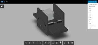
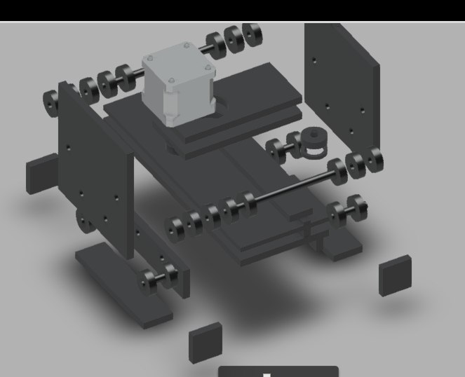
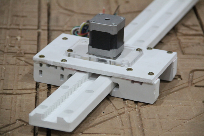
I designed a Linear guide rail carriage for our robotic arm, I designed the rails design on Fusion 360.The images shown below are the screen shots of Rail design. My main design intent was to make all the parts using the machines available in our lab. So as to eliminate to buy any parts to be bought for the rails. So the first design was to cut the rails, rollers everything in acryllic, and to have a stepper motor drive integrated to a moving carriage supported on rollers. This design is illustrated in the below images and CAD model.
But later, I found that having this many moving parts is not a very good idea considering the precise movement expected from our machine. So I explored various other ideas, and during one of the weekly lecture sessions Neil mentioned about fabricatable-machines. I explored the gantry design on github, and found that to be simple and robust for our operation.
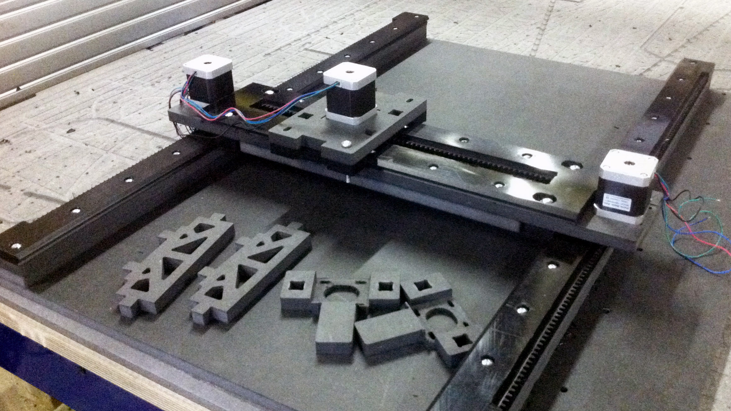
So myself and Rahul decided to make the gantry rail design for the rail for our fabarm. The main fabrication of this was lead by Rahul on the shopbot, and following is the rail we made using some of the scrap foam boards available in our lab. For the detailed fabrication process using shopbot on the making of this rail including the in progress images, please see this link.
Support for Fabrication
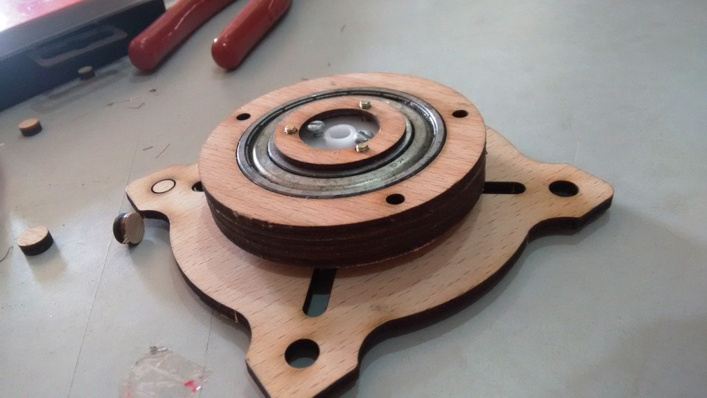
I also supported the fabarm assembly by providing designs for some custom built parts. This was required mainly because we did not had many parts available locally, so we started to buy the nearest fitting parts. One of the main part is the bearing, and we were not able to get hold of the exact bearing, and instead I decided to put a used bearing found from a mechanics shop. There were some design changes required due to this. And I measured the bearing and changed the 2D files and cut the parts on plywood using the laser cutter in our lab.
After cutting the arm parts in laser cutter, I also helped with the assembled the parts with screws and other fastners.
Machine Design - Automating the FabArm
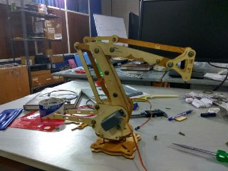
The fabarm we made needs three servo motors and one stepper motor. These motors are illustrated in the image below.
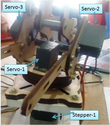
We were using the Arduino to control the motors. Initially the motors are tested and controlled one by one. Ajith and Renjith were tasked with connecing the motors. I was then tasked to test these servos. For controlling the servos, I used the servo library of Arduino, which was pretty straight forward considering the documentation available for servo control using Arduino. The servo motors are tested one by one using the reference code available in the Arduino website. After testing the servo motors one by one, all 3 servo motors are combined together in a single code with the 2 potentiometers. So that I could adgust the servo position by tuning the potentiometers. Need to note that the servo-2 and servo-3 are connected to the same potentiometer as they need to be rotated together.
//based on the single servo code on arduino.cc and revised by jimseelan to include 3 servos.
#include <Servo.h>

Servo myservo1;  // create servo object to control a servo-1
Servo myservo2;  // create servo object to control a servo-2
Servo myservo3;  // create servo object to control a servo-3

int potpin1 = 0;  // analog pin used to connect the potentiometer-1 mapped to servo-1
int potpin1 = 1;  // analog pin used to connect the potentiometer-2 mapped to servo-2 and servo-3

int val1;    // variable to read the value from the analog pin-1 ie the potentiometer-1 mapped to servo-1
int val2;    // variable to read the value from the analog pin-2 ie the potentiometer-2 mapped to servo-2 and servo-3

void setup() {
  myservo1.attach(9);  // attaches the servo on pin 9 to the servo-1 (needs to be a pwm pin)
  myservo2.attach(10);  // attaches the servo on pin 9 to the servo-2 (needs to be a pwm pin)
  myservo3.attach(11);  // attaches the servo on pin 9 to the servo-3 (needs to be a pwm pin)
}

void loop() {
  //Controlling Servo-1
  val = analogRead(potpin1);            // reads the value of the potentiometer-1 (value between 0 and 1023)
  val1 = map(val1, 0, 1023, 0, 180);     // scale it to use it with the servo (value between 0 and 180)
  myservo1.write(val);                  // sets the servo-1 position according to the scaled value
  delay(15);                           // waits for the servo to get there

  //Controlling Servo-2 and Servo-3
  val = analogRead(potpin2);            // reads the value of the potentiometer-2 (value between 0 and 1023)
  val2 = map(val2, 0, 1023, 0, 180);     // scale it to use it with the servo (value between 0 and 180)
  myservo2.write(val);                  // sets the servo-2 position according to the scaled value
  myservo3.write(val);                  // sets the servo-3 position according to the scaled value
  delay(15);                           // waits for the servo to get there
  }
I have used the above code only for testing the servo motors, And the code was further improved and customized a lot for use with the fabarm, by Ajith and Renjith. The final code used in the fabarm including the code for the stepper motors using a Fabnet board and a Gestalt node and is available here.
Concluding thoughts
My key contribution included leading the concept generation (by organising a structured brainstorming), development of the rails (creation of CAD models in Autodesk Fusion), making bespoke parts to fit locally sourced materials (design, laser cutting and assembly of bearing support rings), layout of the control system (servo motor layout and testing), and assistance in testing the arm. I have also made the presentation slide for the fabarm; this and further details could be found on our group page.
The machine building activity was both interesting as well as demanding activity wherein we learned lot of technical stuff (including the development of various parts like the rail, the issues with the friction of materials like the acryllic etc). We also understood the soft skills on working with a diversly skilled team like having the need for a well written plan with clearly distinct roles and responsibilities. We also understood the need of having a proper local supplychain for getting the various raw materials for these sought of projects, as many of the standard parts are not available locally. If we had more time we also should have made an useful end effector so that some machining of low density materials like foam could be done.