9. MECHANICAL DESIGN - The FabARM
Index
- Assignment
- Introduction
- Making the prototype in cardboard
- CAD modeling spacers and standoffs
- CAD modeling the object holder (end effector)
- Problems faced
- Summary
A. Assignment
- Make a machine, including the end effector, build the passive parts and operate it manually..
B. Introduction
This week we are working as groups to design a machine. Machines are of wide range and our
primary task is to identify
the right thing we want to make for this week. Many ideas such as a Foam cutter machine, robotic arm etc
was proposed and the majority
finally agreed upon the Robotic arm on rails. The concept was to make a 4 axis robotic arm which will be
placed on a 2 axis rails.
This arm can be used to pick and place objects further it can be extended to do 3d printing and
engraving. The concept of the arm is
inspired from the Uarm. I was assigned the work of developing the initial design drawings
and proof of concept.
Link to the group page
The following are the initial drawings i make for the project.
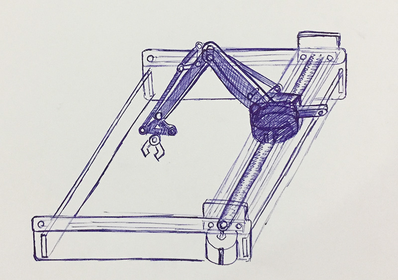
Complete machine drawing.
This image shows the initial stage drawing to put the concept into paper. Here you can see a robotic arm
with an end effector,
mount on a 2 axis CNC. The 2 axis CNC will be controlled by 2 stepper motors. A belt drive will be used
to move the arm in the slides.
The second drawing is that of the arm. I am planning not to put the servo on the back and not on the
top joints to make the design
more stable and to balance the weignt. If we put the servo on the top joints we would need more
powerfull servos on the bottom.
So the plan is to put both the servos on the base and if needed will put a small servo for the end
effector.

Robotic arm drawing.
c. Making the prototype in cardboard
Here the arm is the most critical part of the machine. So we need to be very careful in
designing and developing it.
We thought to look on the urm arm website for help. Fortunately, they had all the design files available
in open sourse. We wanted to know
how everything connects togather. So we pulled out the design files from thingverse and
started to cut them in cardboard
so see how it connects. Though all the files where available in thigverse, they where no ready to cut.
There where extra lines and parts in
the design which was available. Primarly we had to clean up the files to just select the wanted parts
and leave out the remaining.
All these fixes where done and later we proceeded with cutting the parts in the cardboard.
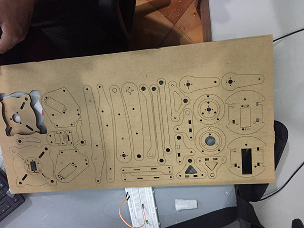
Cutting in cardboard.
We used threads to tie the parts togather.
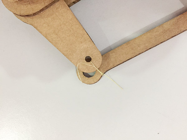
Parts ties up with threads.
After getting an idea by tieing parts togather we later connected the parts with sticks.
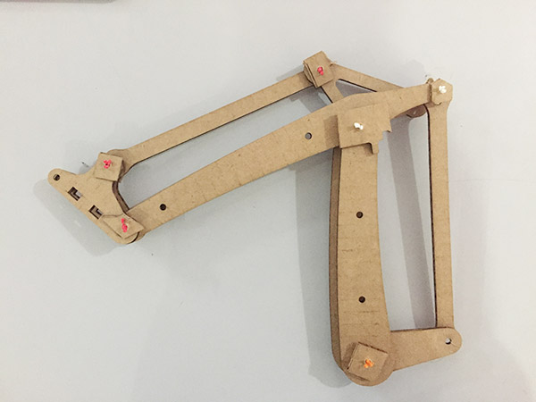
Prototype of the arm.
As we made the arm and tested out the design we moved on to making the same in craftwood. The major issue we are about to face is the unavailablity of nuts, bolts, spaces etc. So we have to find substitute for them or have to change the design to use the parts we are having. We desided to stick on with the design and 3d print the spaces and other components required. We could nt find bearings of the required size so we even had to slightly change the designs.
b. CAD modeling the spacers and the standoffs
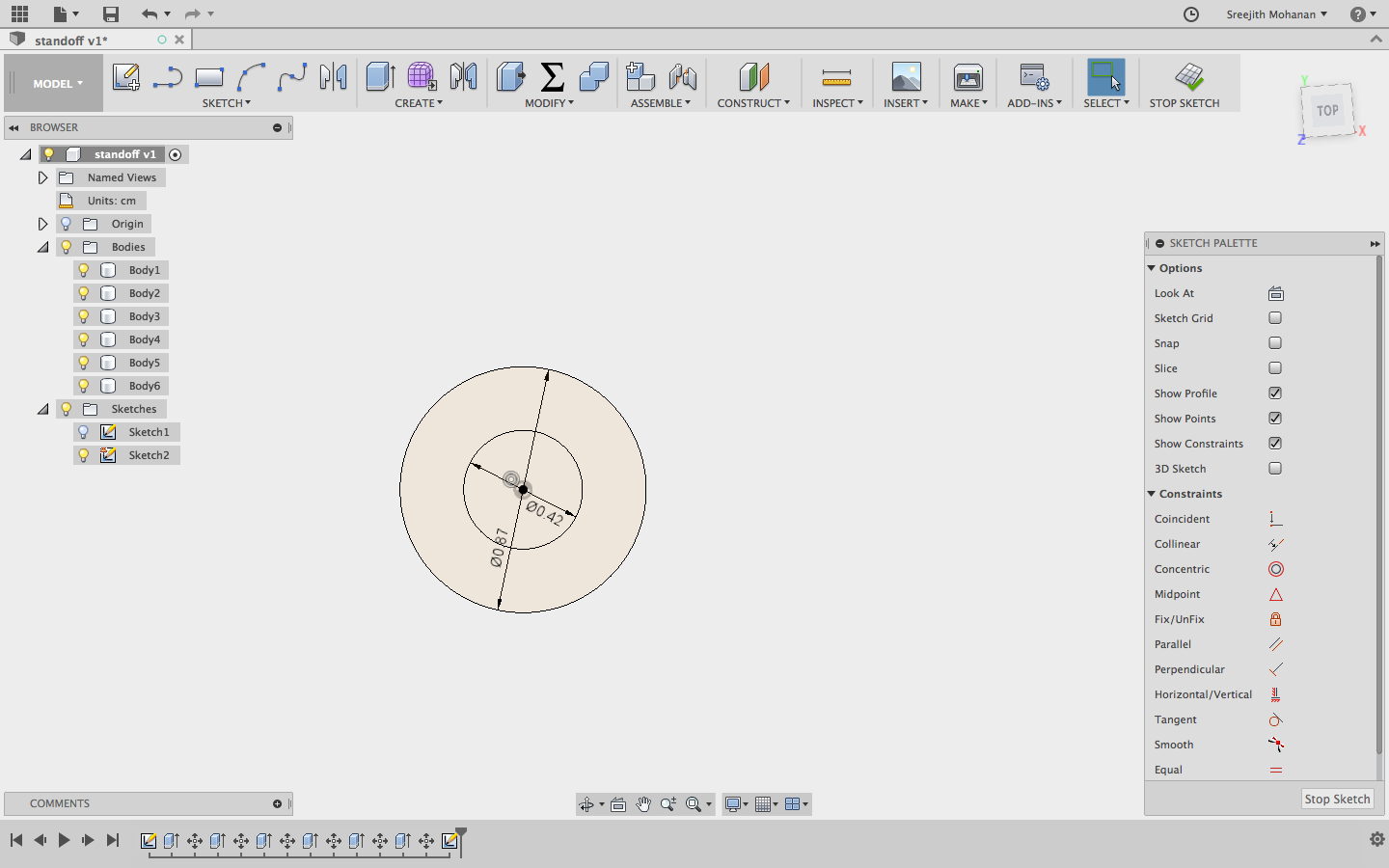
Due to inavaalbality of spaces and standoffs of required size we had to 3d print them. As is it a simple
passibe mechanical part it is an ideal candidate for being 3d printed. The following description and
screenshots show how i made them. I have also embedded the 3d models.
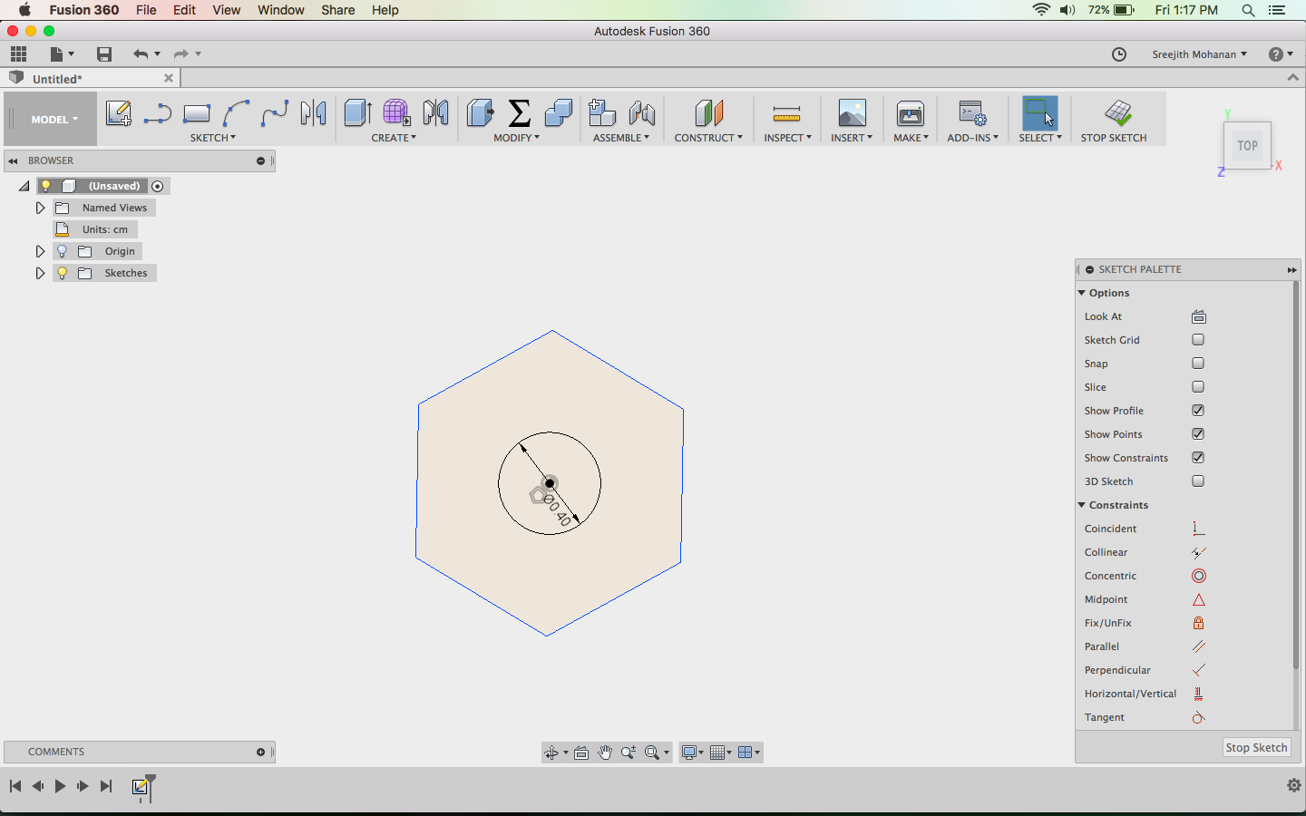
The basic sketch
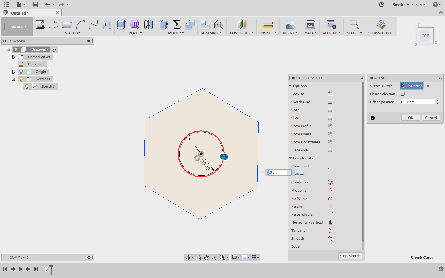
Giving allowance for the screw
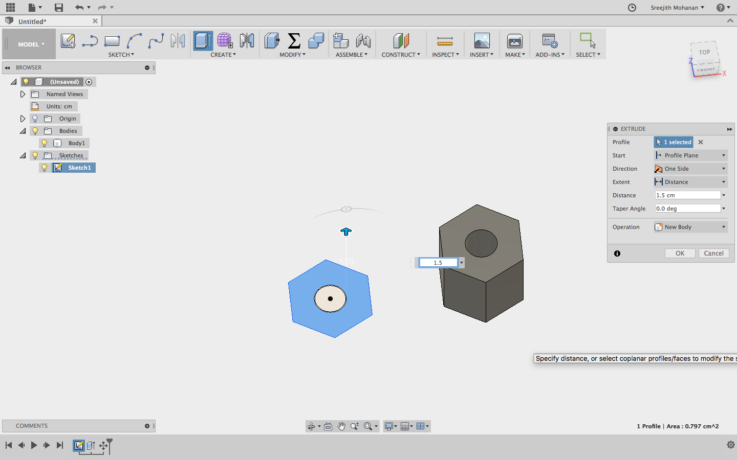
Extruding to create the shapes
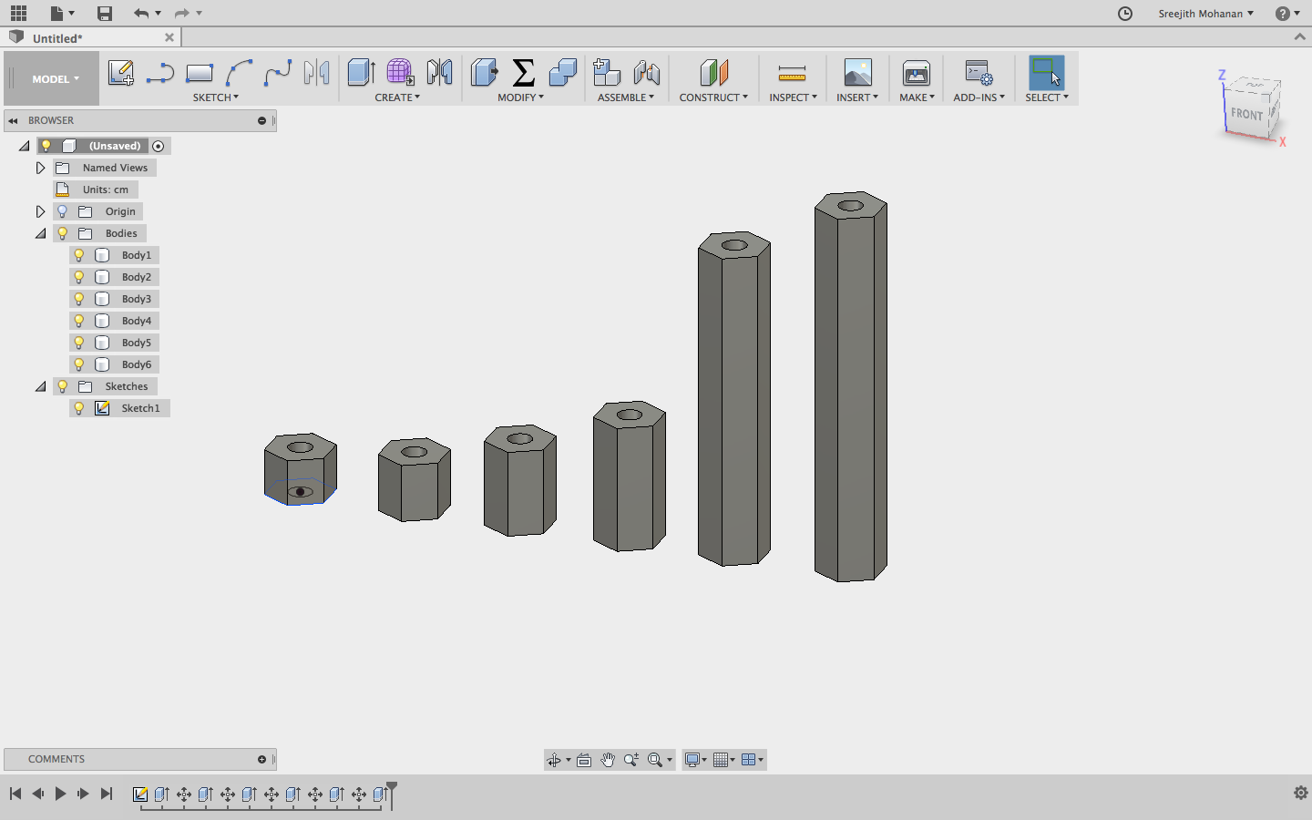
Creating standoffs are different heights
Sketch for the spacer
![]()
Final rendering
Final design
Original fussion
file
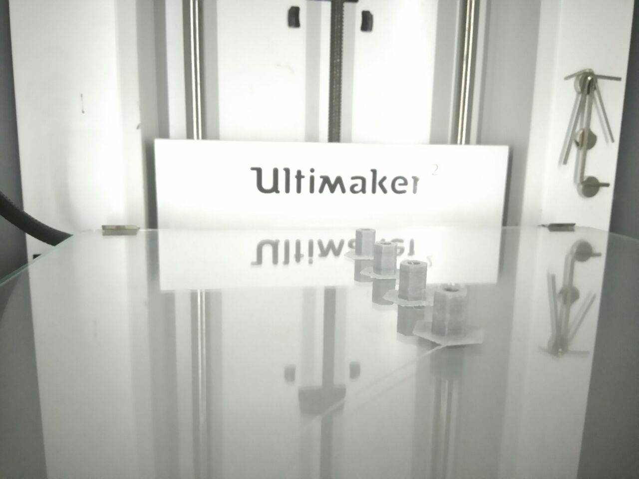
Finally we 3d printed the items using ultimaker.
![]()
3d Printing spacers and standoffs
c. CAD modeling the object holder(end effector)
Another thing i designed during the week is the object holder. You can see in the
initial drawing i make, the arm has an object picker. Now i am designing that. This end effector
is not a part of the U arm. But this is something which we want to add in extra. The U arm has
a different model of the same. The following steps shows how i designed it.
I started off by drawing the item. This is the drawing i made. I used this drawing as reference
and made the parts in fussion.
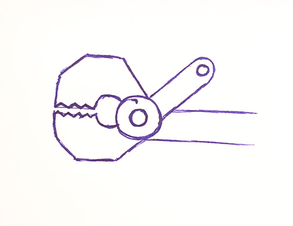
Drawing
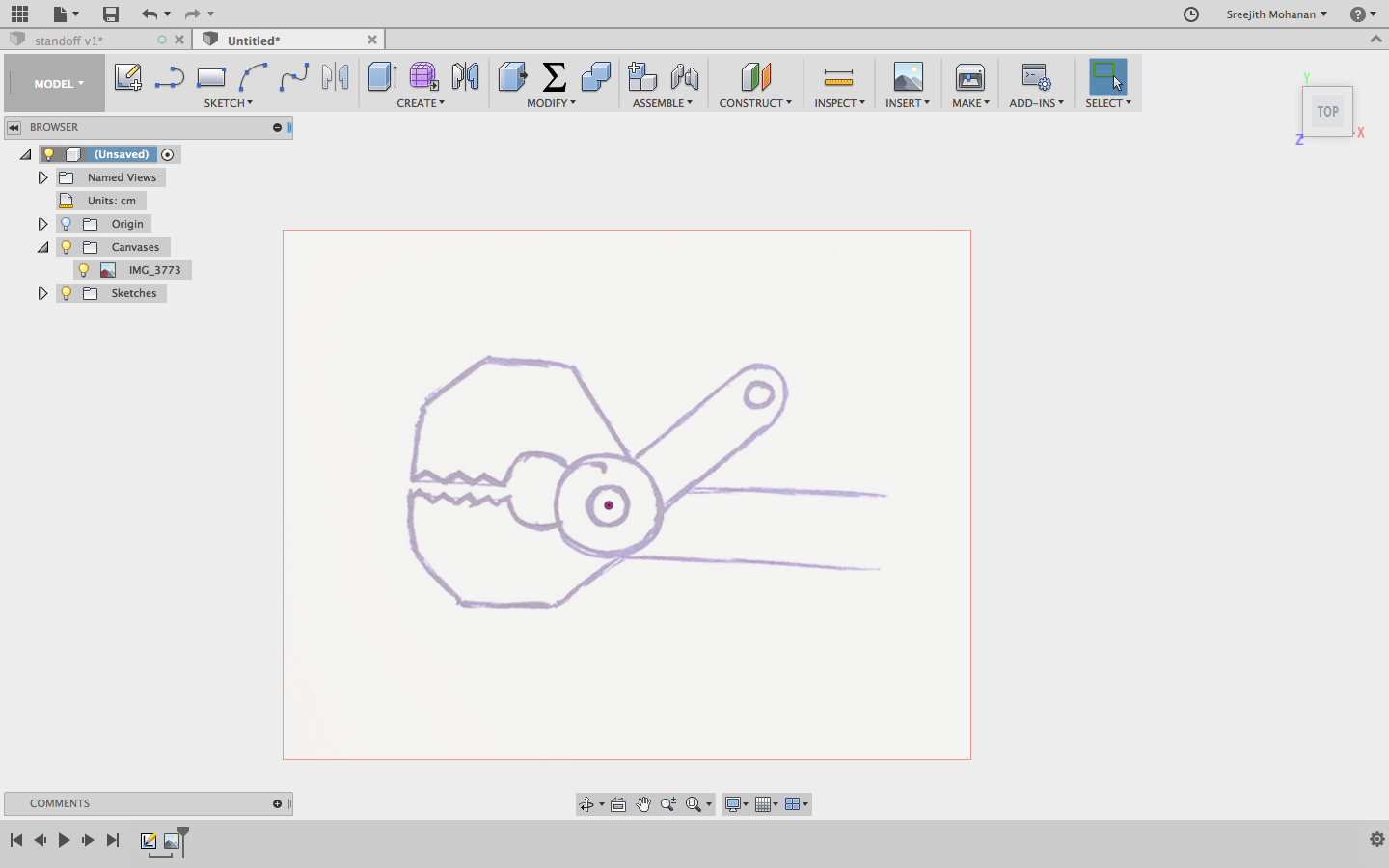
Importing the drawing to fussion
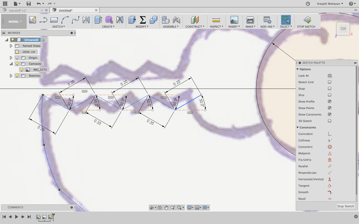
Creating the sketches
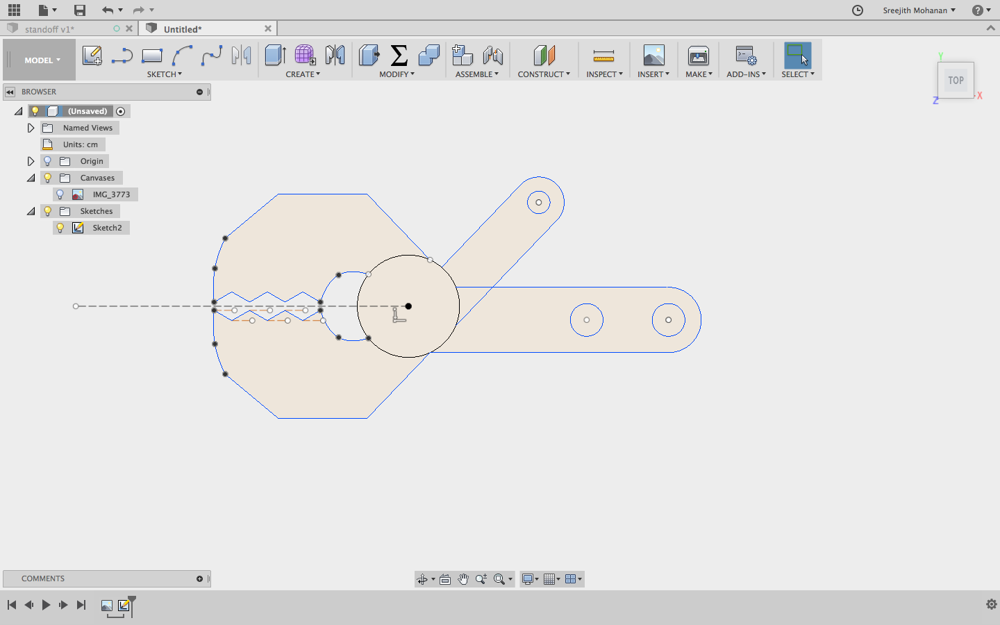
Final sketch
Extruding and making the parts with proper allowance
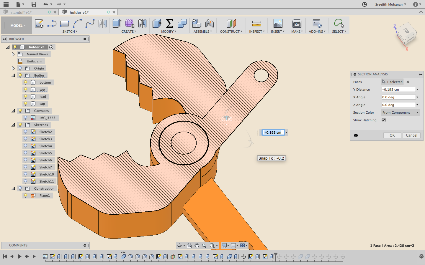
Section analysis
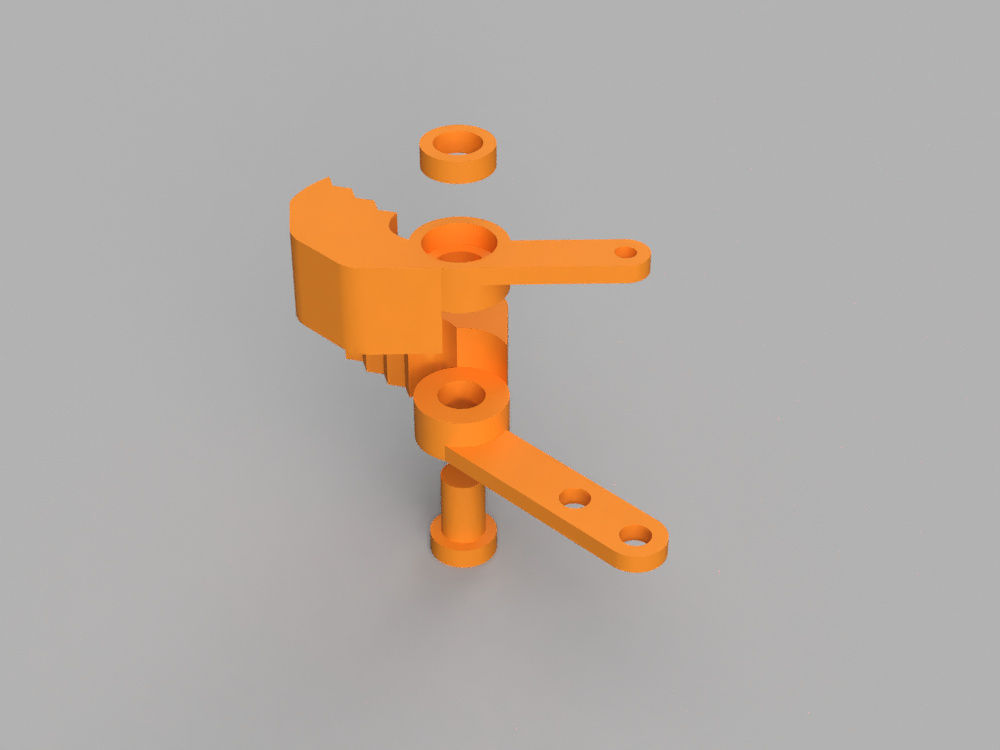
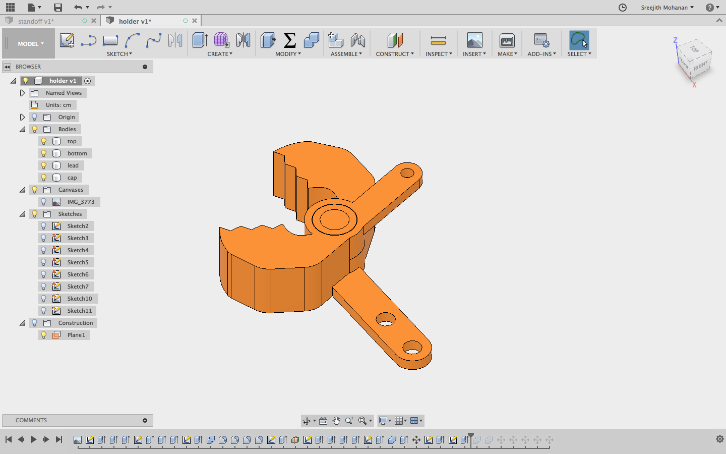
Holder parts view
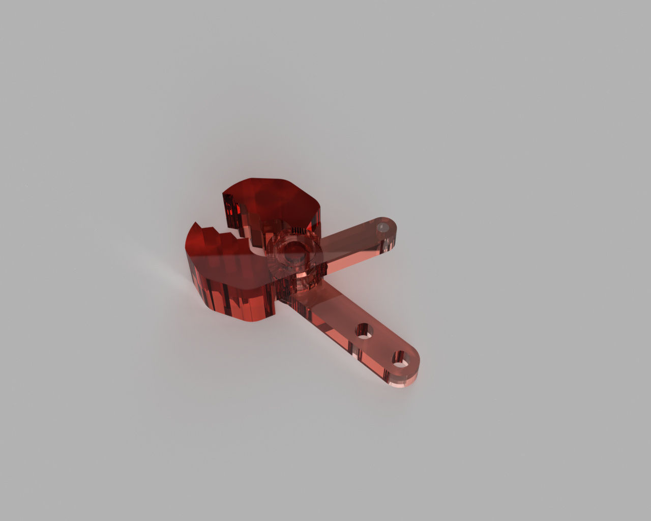
Render in transparent material for better view
Final cad design
Original fussion
file
Finally i got it 3d printed. The following are the parts after a little bit of clean up after 3d printing.
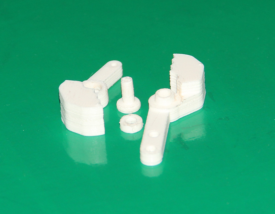
3d printed parts
Then i assembled the parts as in the following video.
Assembling the parts parts
Finally mounted the object picker to the Fabarm.
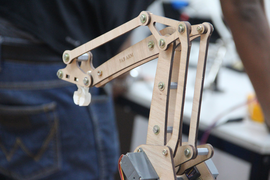
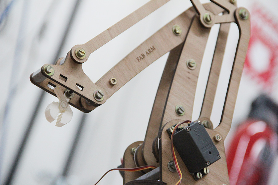
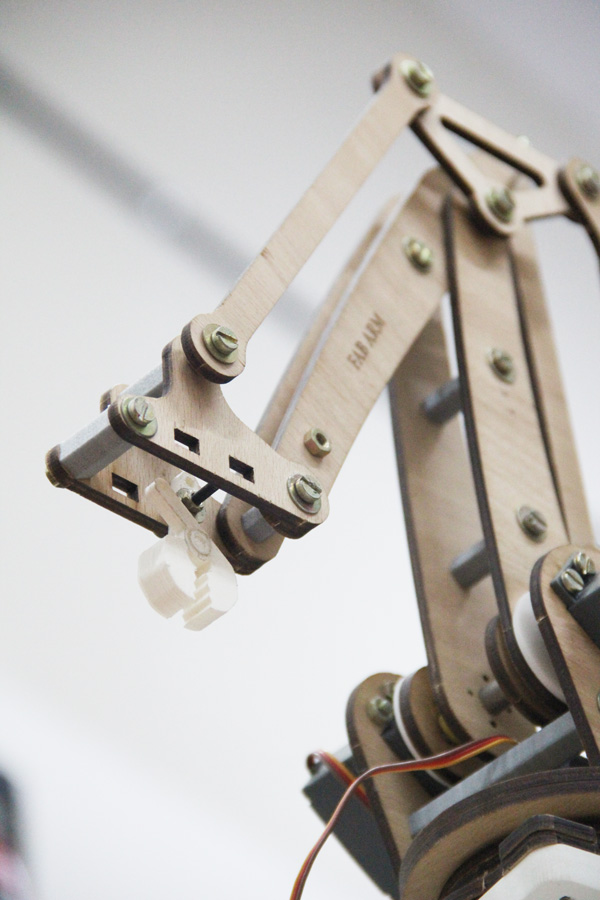
Object picker mounded to the fabarm
Then i tried testing the end-effector manually. I connected a steel rod to the moving arm. Pulling the rod will open the
jaw and pushing it will close it. The following is a manual demonstration of using the end effector for picking and placing.
manual testing
Review
The design and working of the claw looks good, the only suggestion was that it could have been little bigger in size. My plans for a next version is that, i need to design and make a mechanism which will move both the jaws together compared to single jaw moving in this design. Making both the jaw move will give more control over picking. Also i wont choose white material for making the claw because it gets dirty while filing. Also i would like to increase the number of tooths of the jaw for the next version as that will help my claw pick smaller objects too. The issue with this design is that the big gap between the tooth allow small objects enough space to fall down. The servos we used in our project where not the ones prescribed in the original design. We couldn't find the prescribed ones thus we had to substitute them with what was available with them. These steppers are not powerful enough for moving the arm beyond around 30-40 degree. In the next version i would like to modify the design in such a way that it can accommodate bigger and more powerful steppers which we are having. I would also like to get the flanges and the bearing as it can make a lot of difference in the robotic arm. Without all of that the machine is quite jerky and has lot of energy dissipation due to friction. My plan is to find at-least closer items and make design changes to fit them.
d. Link to the group project page
e. Problems faced and their solutions
- During the 3d printing of the claw, the lead which connects the two jaws together had a small bulge on the bottom. It seemed like extra material was deposited on that part. On inspection i could found that the length and other dimensions of the part was right. This small deformation was the only problem. I fixed this by simply filing away the protrusion. After filing everything was perfect and fitted well.
- The major problem was the unavailability or screws, nuts and bearings which was available in the original design. We had to find substitutes for most of them. Some of them we made it by 3d printing.
- We could'nt find flange bearings for assembling so the assembly is not quite smooth.
- We had to reverse our plans for the material of fabrication. It was planned to make the arm in 4mm acrylic, but the servos we had where not capable of taking the weights so we moved on to 3mm craft wood which was much lighter.
f. Summary
- Make the initial drawing of our robotic arm.
- In a group effort make all the mechanical parts of the arm including the end effectors

This work is licensed under a Creative Commons Attribution-NonCommercial-ShareAlike 4.0 International License.