Composites
3D Design and Milling
For this week's assignment I wanted to make a modem stand. So, the first step was to design my piece using Fusion. After designing it, I put it on a box so that I can mill it. For more info on how to use Fusion, you can check the 3D Scanning and Printing week.
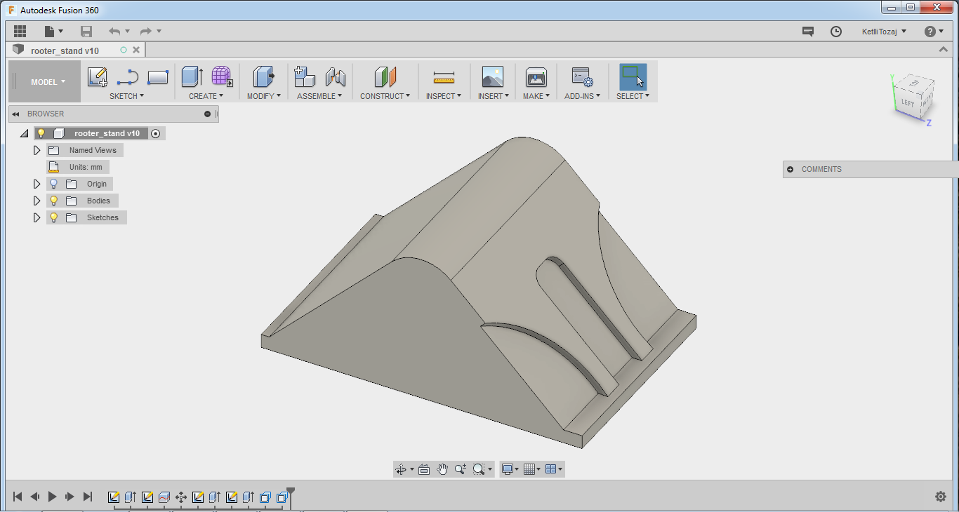
After the design was ready, I went to the CAM process in order to generate the .gcode. The forst thing to do was to install a Cloud Post Processor. The post processor used was eLsign_last.cps - A360. Instructions on how to install the Cloud Post Processor can be found here. After installing the post processor, I had to add the tool and holder of the eLsign machine. To do that, I went to tool library and added a new tool and holder for this tool with the parameters seen in the pictures below.
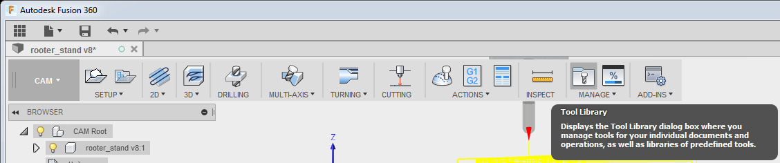
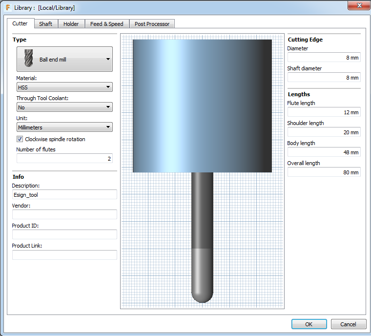
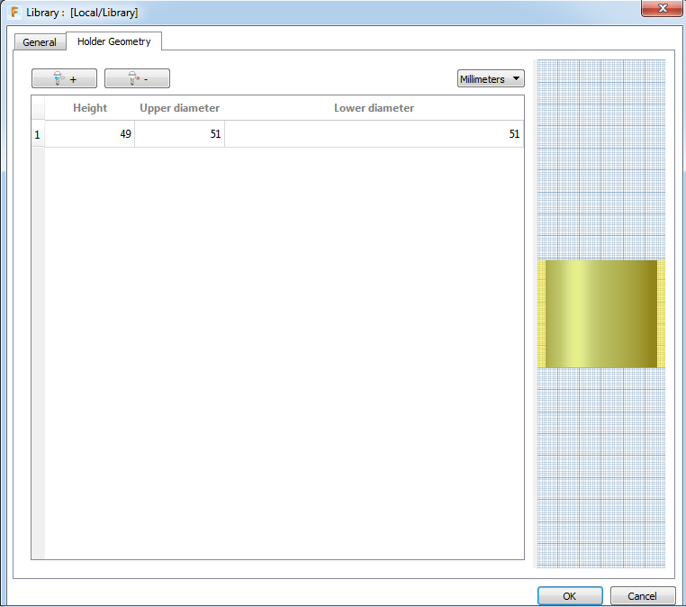
After adding the tool and holder, it was time to proceed with the CAM processing as I did on Molding and Casting week.
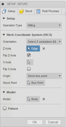
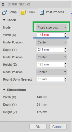
I created a new setup and set the parameters needed. On the Stock menu on the Setup, I chose fixed size box and I made the X-dimension of my box slightly smaller in order to make sure my piece will be milled properly. I knew the dimensions of the box as I cut the box of the foam according to the needs of my design.
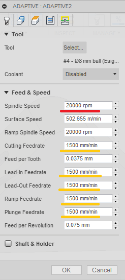
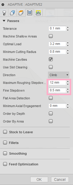
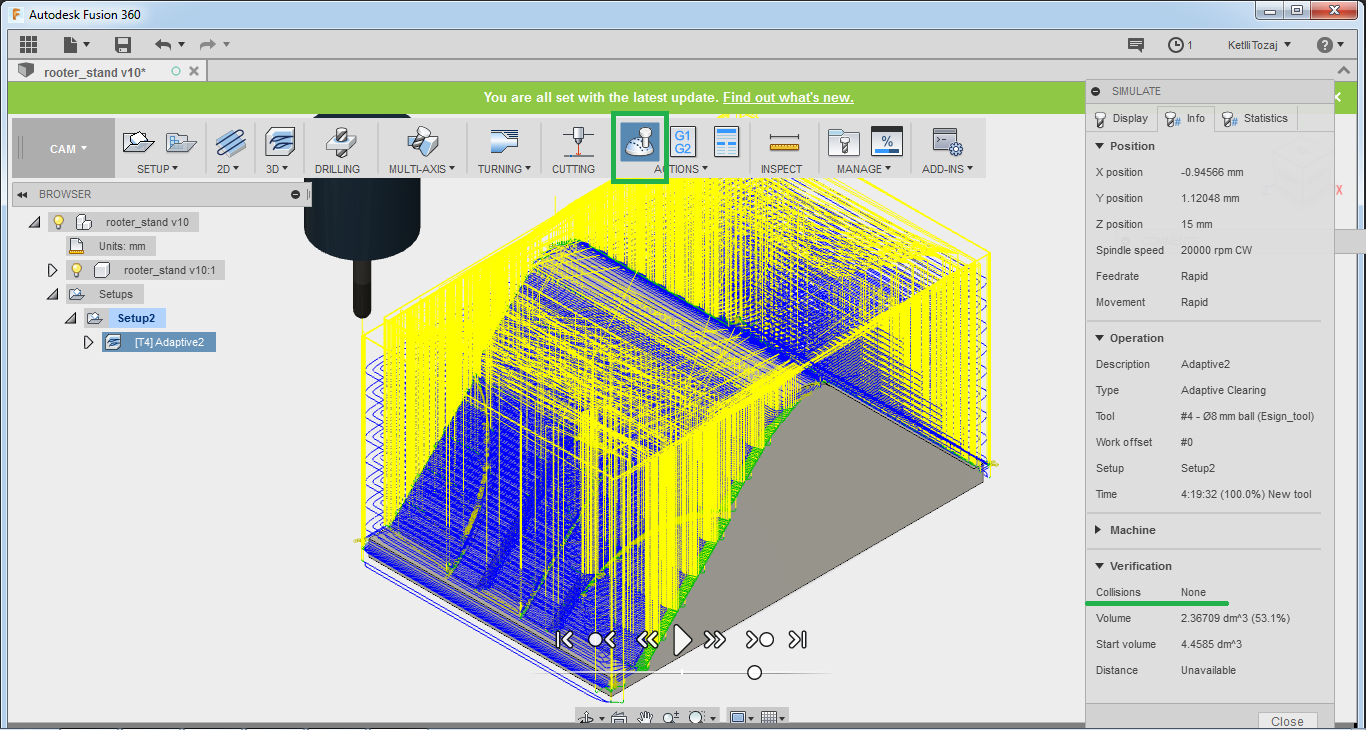
After the new setup, I had to set the parameters for the 3D Adaptive Clearing. The only parameters need to be changed were on the tool and passes menu. On the tool menu I set the spindle speed to 20000rpm and all the feedrates to 1500mm/min. To the passes menu, I set the maximum roughing stepdown and the fine stepdown.
After everything was successfully set, it was time to do the simulation on order to check if we have any crushes occured during the milling process. Fortunately, in my case there were no collisions so I proceeded with milling. But, in case there were collisions, I had to go through each one of them to see what actually happens and if there is an actual collision (as the simulation sometimes may be mistaken). If that is true, we should change the design in a way that no collisions will occur.
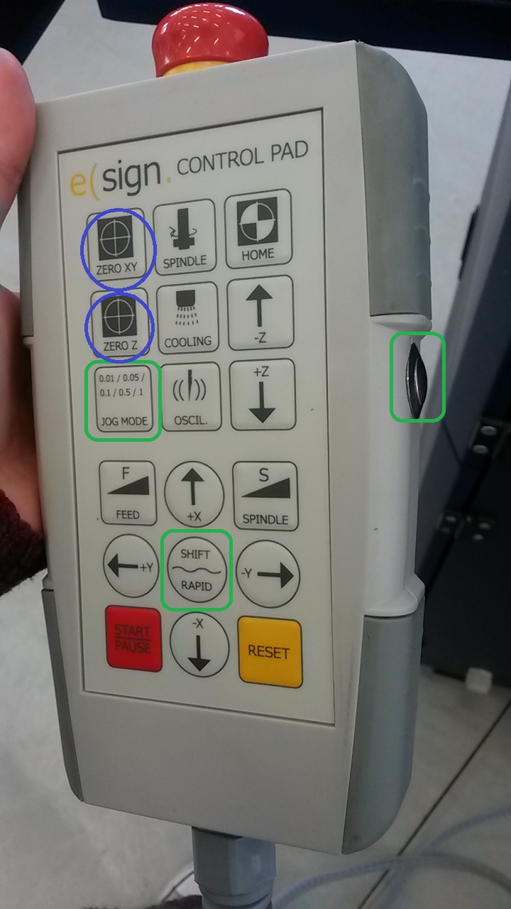
After the software part was over, I proceeded to mill. First thing to do was to align my piece correctly, turn on the vacuum and home the axis. From the CNC's main menu, I went to the user's menu to turn on the laser. When we turn the laser on, the tip of the machine goes down a few millimeters. Firstly, we home the x and y axis and then the z. After home each one of them, we press home XY and home Z respectively. For the homing of the z axis we use a small tool that we place on the top of the piece to be milled. Then we press the F2 to the user's menu.
To move the laser we hold the side button and shift and then the direction (arrows) to which I want the laser to move to. For a slower movement we click the button with the steps as many times as needed to set the steps we want. When we want to get the previous speed back, we go to the software of the CNC machine and press continuous. Before of course setting any parameters we have to get the tool we are going to mill and home the machine according to that tip.
Because all the settings of the spindle etc were set to the .gcode at fusion we did not need to go in such detail as we did on Computer Controlled Machining. But, of course for more details on how to use the big CNC machine, refer to the week mentioned. After we loaded the process and initiated it, I increased the speed of the spindle on the fly on the Auto menu using F9 and F10 buttons.


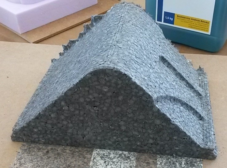
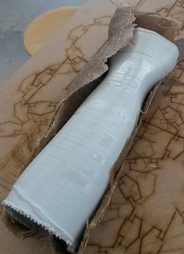
After all this process, the milled piece looks like this:
Apart from this piece, I also did the composite of the hand I 3D printed on the 3D Scanning and Printing week.
Making the composite
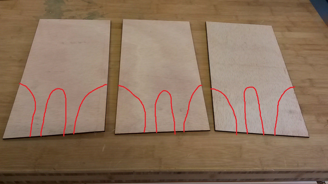
The first step of me making the composite was to laser cut wooden pieces matching my design. In the picture below, the pieces were further laser cut later to the appropriate shape of the design but it is not illustrated below as documenting it, skipped my mind. The red lines indicate the position of the further cutting of the pieces.
So, for the composite I used wood that I pre-checked if it bends as my design has a 90o angle with a fillet that needed to be achieved without the wood breaking, and glass fiber. Now, an important thing to remember is that when in any contact with the glass fiber, gloves need to be worn at all times as it is dangerous when it gets into contact with your skin. Small glass pieces can enter your body and cannot be removed causing severe health problems on the long run.
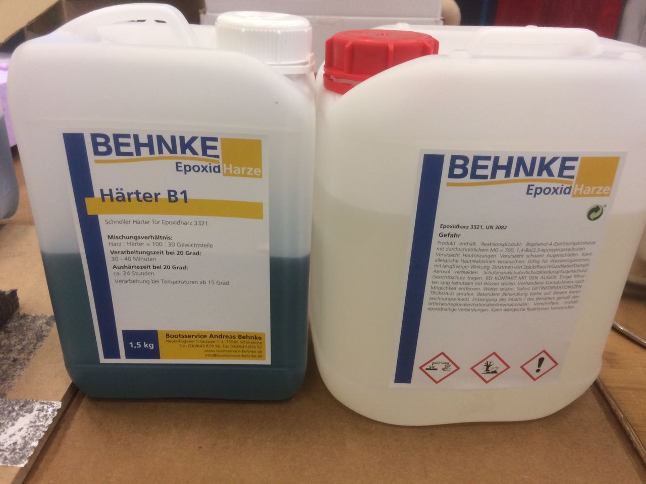
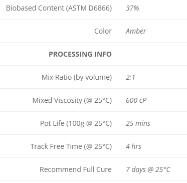
After everything was set, it was time to use the Epoxy for the mixing of the solution. The usage and the mixing ratio of the epoxy was determined by the datasheet.
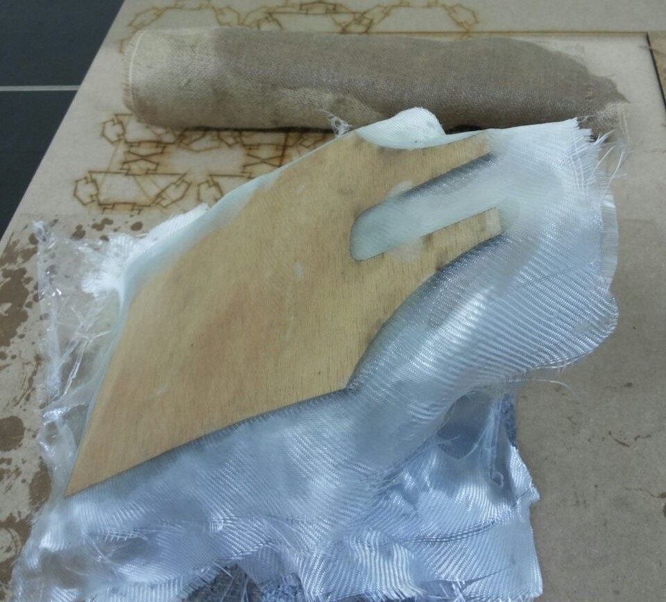
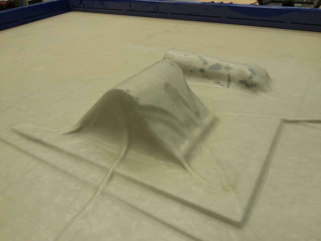
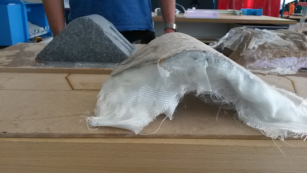
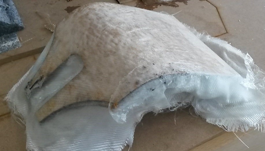
After the solution was ready, the procedure of the making of the composite started. So, first is the wood, in between the glass fiber with a generous dose of solution on top and so on. Glass fiber is only put in between of the wood or any other material we are using. I was about to do the same but the third layer of wood on top would not bend any more so I skipped it. After applying the above-mentioned method, the initial result looks like this:
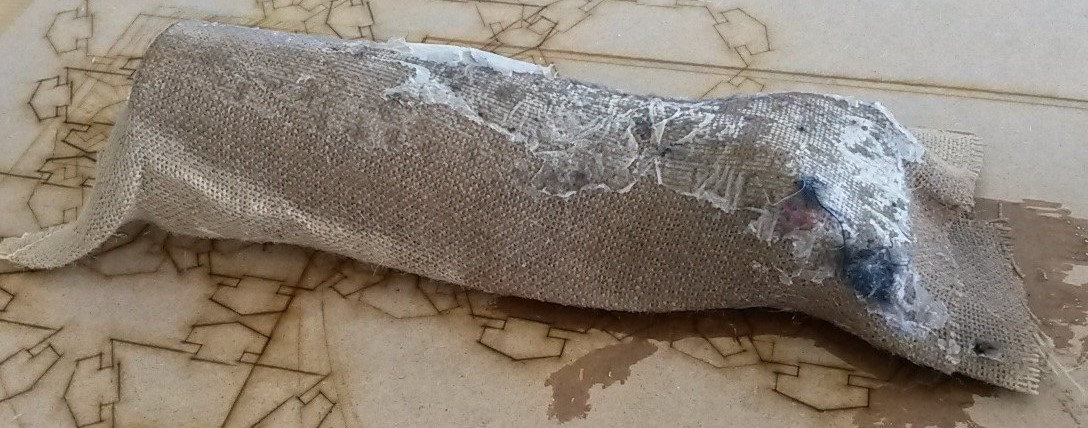
Same method was also used with the hand but there I only used normal fiber. So, in this case it would be only fiber, solution, fiber, solution and so on. So, after applying the above-mentioned methods, the initial result looks like this:
Next step is the vacuum machine. I put the pieces on the vacuum machine and covered them with a cover sheet. After I closed the vacuum machine using the handles and turned the handle in the middle to allow the pressure to come out when I turn on the machine.
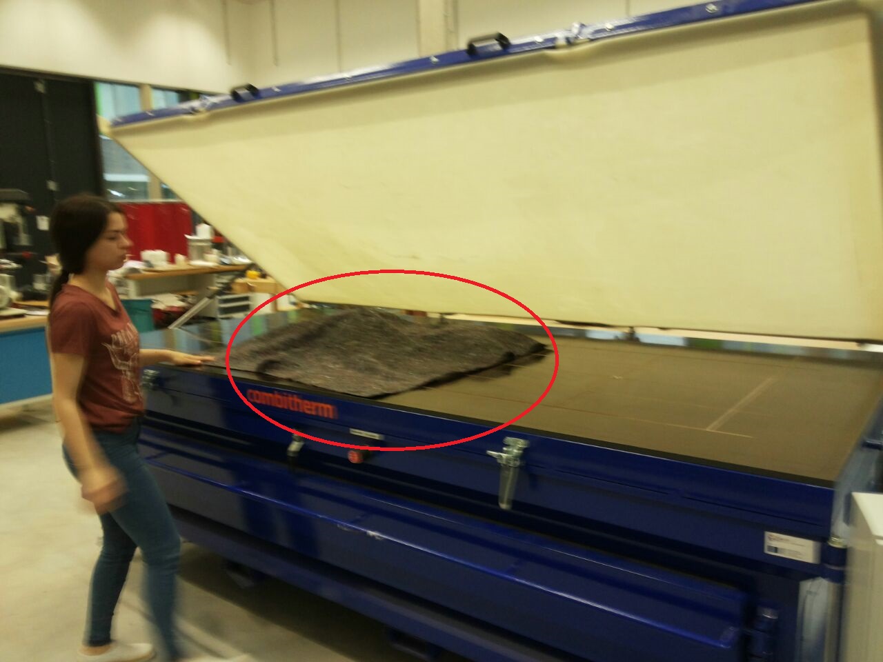
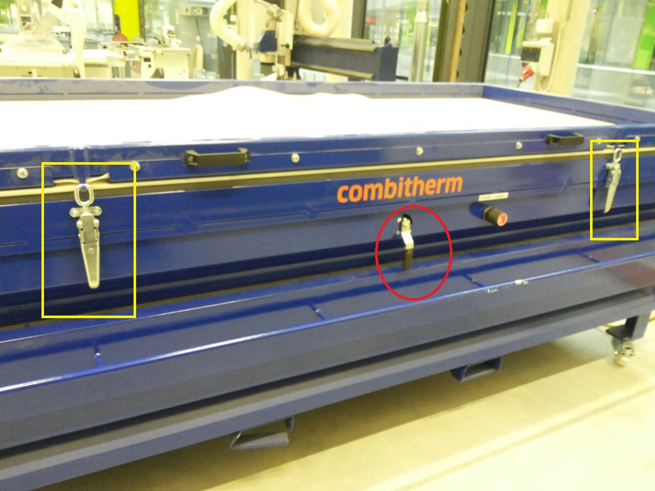
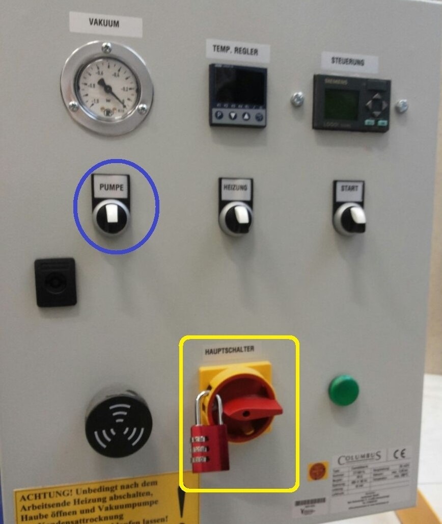
Everything is ready, so after my supervisor unlocked the on/off for the vacuum machine, I turned it on and then used the pump function to create a maximum pressure inside the vacuum chamber. Then, the machine was turned off.
After everything was set, the composites were left overnight in the vacuum chamber.
Results
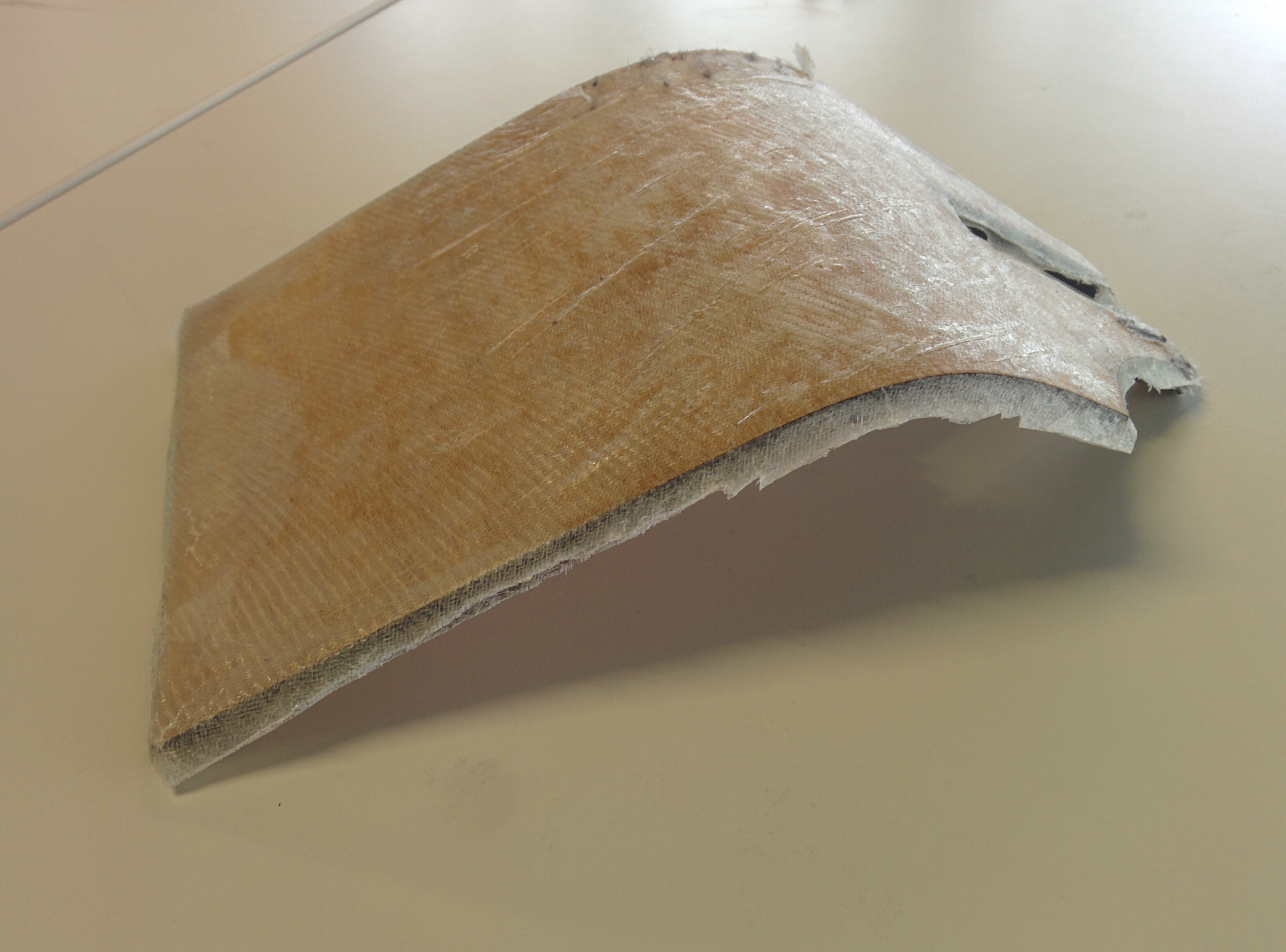
The results of this assignment were not satisfactory at all. This was because of the fact that the vacuum machine would lose its pressure only after a couple of hours and needed to be pressurized every time. This behaviour is not normal and we are checking on it. So, the result was the composites to not fully gain the shape of the designs.
In the case of the hand, the composite was just stuck on it and I could not unstuck it from the design. That was a mistake of mine as I did not use a separator spray before I make the whole procedure.
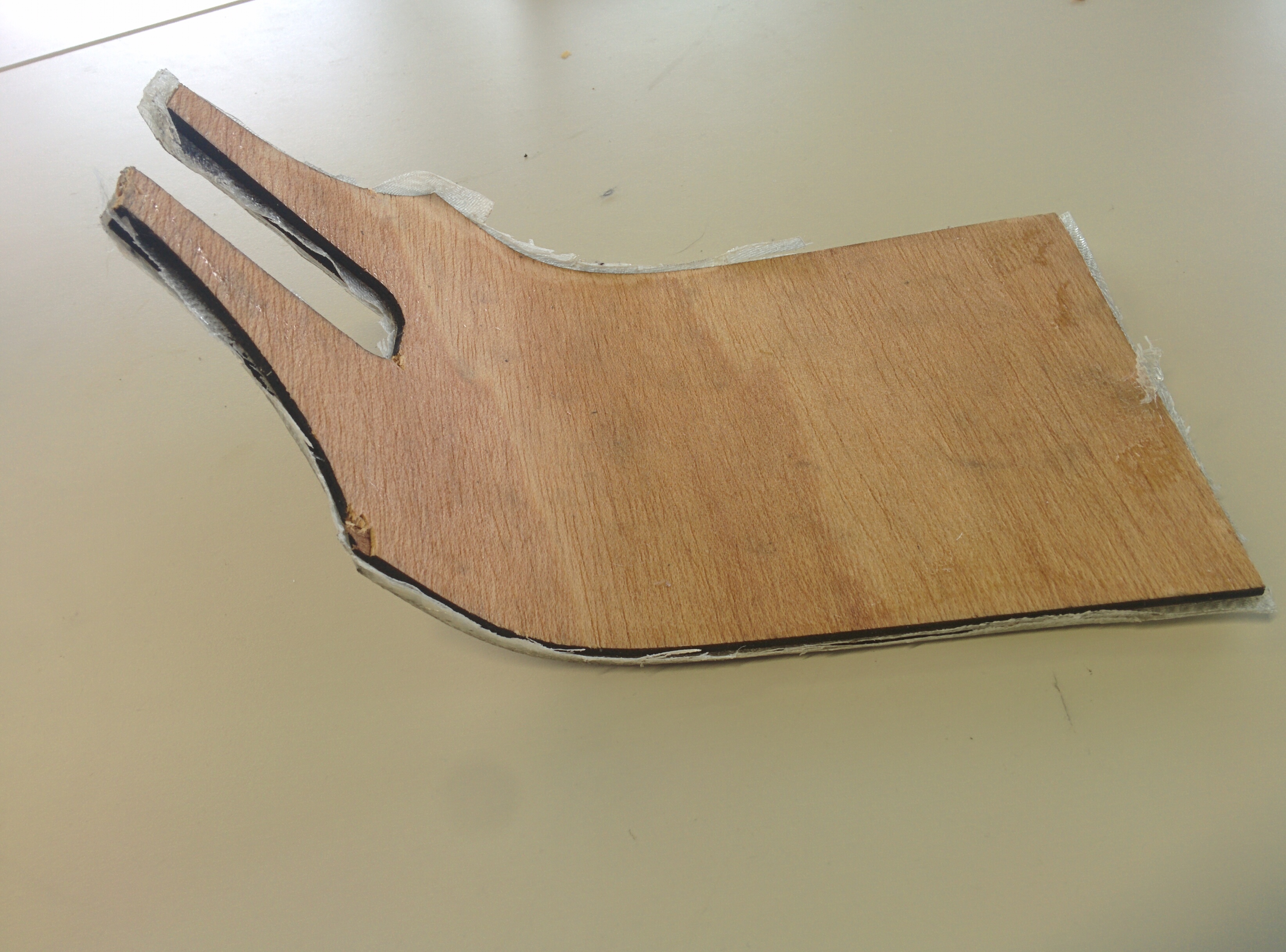
In the case of the modem stand, it failed because of the vacuum which I have to admit it was a little bit disappointing.
Downloads
For the design of the hand, you could go to 3D Scanning and Printing week to download it.