Computer Aided Design

3D Design

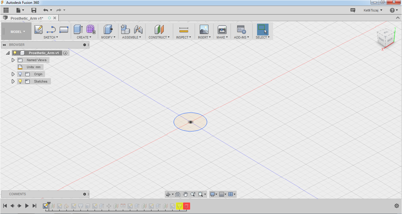
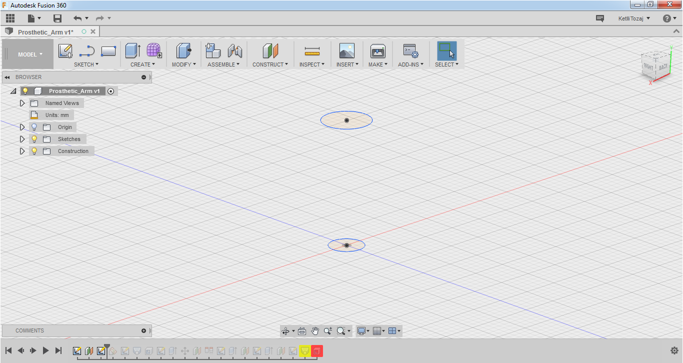
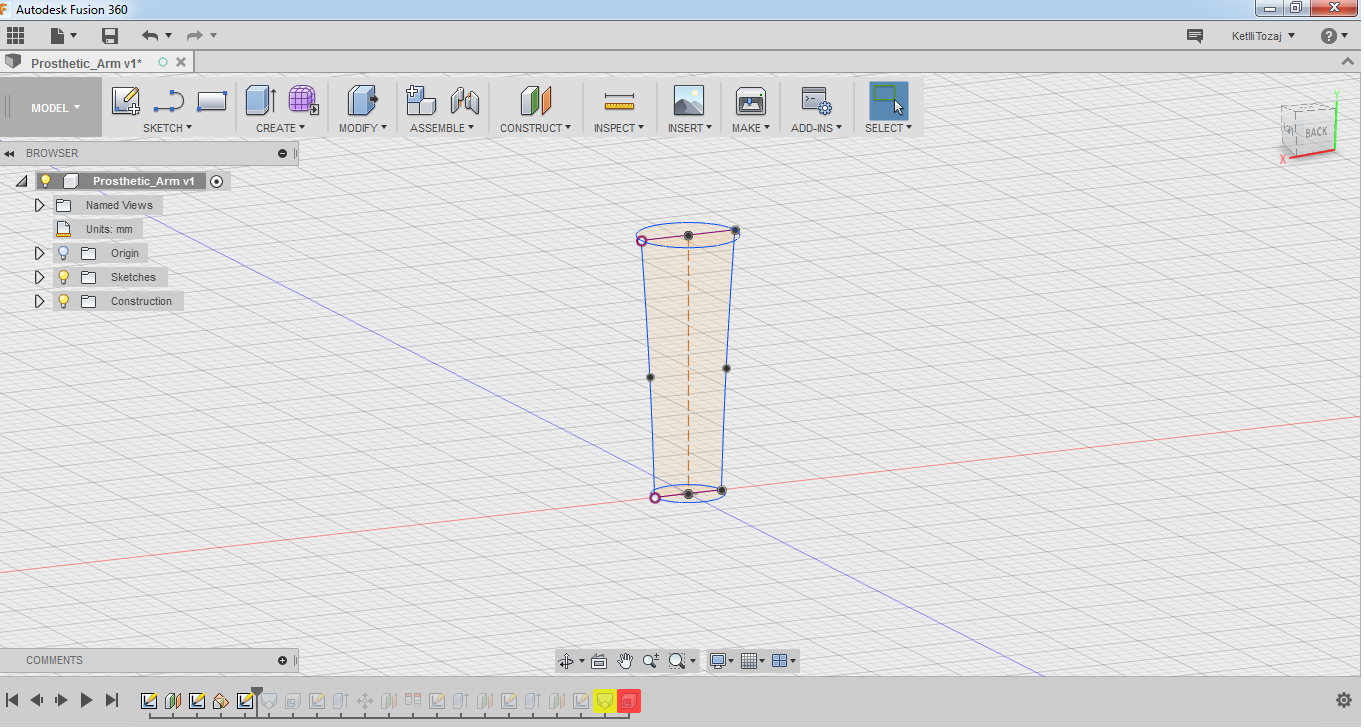
For the 3D Design, I used Fusion360. I also tried FreeCAD in the past, but I decided to use Fusion360 as I find it easier to use. So, I tried to make only one part of the arm. The steps I followed to do this are:

  • On sketch, I pressed "Create new sketch" and selected top. Then I pressed C on my keyboard in order to create a circle with a diameter of 5mm. After that, I stopped the sketch.
  • After that, on construct I selected "Offset Plane" and I selected the plane trajectory and I placed it 18mm upwards. Then, I selected the offset plane, I created a new sketch and I created a circle with a diameter of 7mm and I stopped the sketch.
  • Then, I wanted to use loft but because the arm does not go exactly on straight lines, I used the spline to make curves between the two circles. To do that, I went to construct, pressed "plane at angle" and selected the y-plane.
  • So, I selected the plane at angle, created a new sketch and used the spline. After I made the spline, I selected one end point of the spline and the other end of the z-plane circle and selected coincident in order to be "glued" together. Then I wanted to mirror the spline I had just made. So, I drew a line from the one circle to the other middle points and made it a construction line by selecting it and pressing X on the keyboard. After doing that, I pressed the mirror command on sketch and selected the spline for the object and the construction line for the mirror line and pressed ok.
  • Then I used the loft command under "Create". I selected the circles as loft profiles and the splines as rails.
  • As I want the prosthetic arm to be hollow for maybe passing wires inside, I used the shell command under "Modify". I selected the two circles as the faces and entered a value of 0.5mm.
  • For making the arm lighter and for aesthetic reasons, I also wanted to make holes around the arm. To do that, I used an unusual way as my Fusion was not accepting the other ways at that moment. So, I selected the offset plane under "Create", turned on the origin by lightining the little light bulb, chose the vertical plan and placed it far from the body design. Then I created a new sketch and used lines and the fillet function to make the desired shape. After that, I stopped the sketch and extruded it by using the extrude command under "Create". I selected my sketches, I chose the two-side direction and the cut operation.
  • In order to have the result below, I followed the same steps as above.
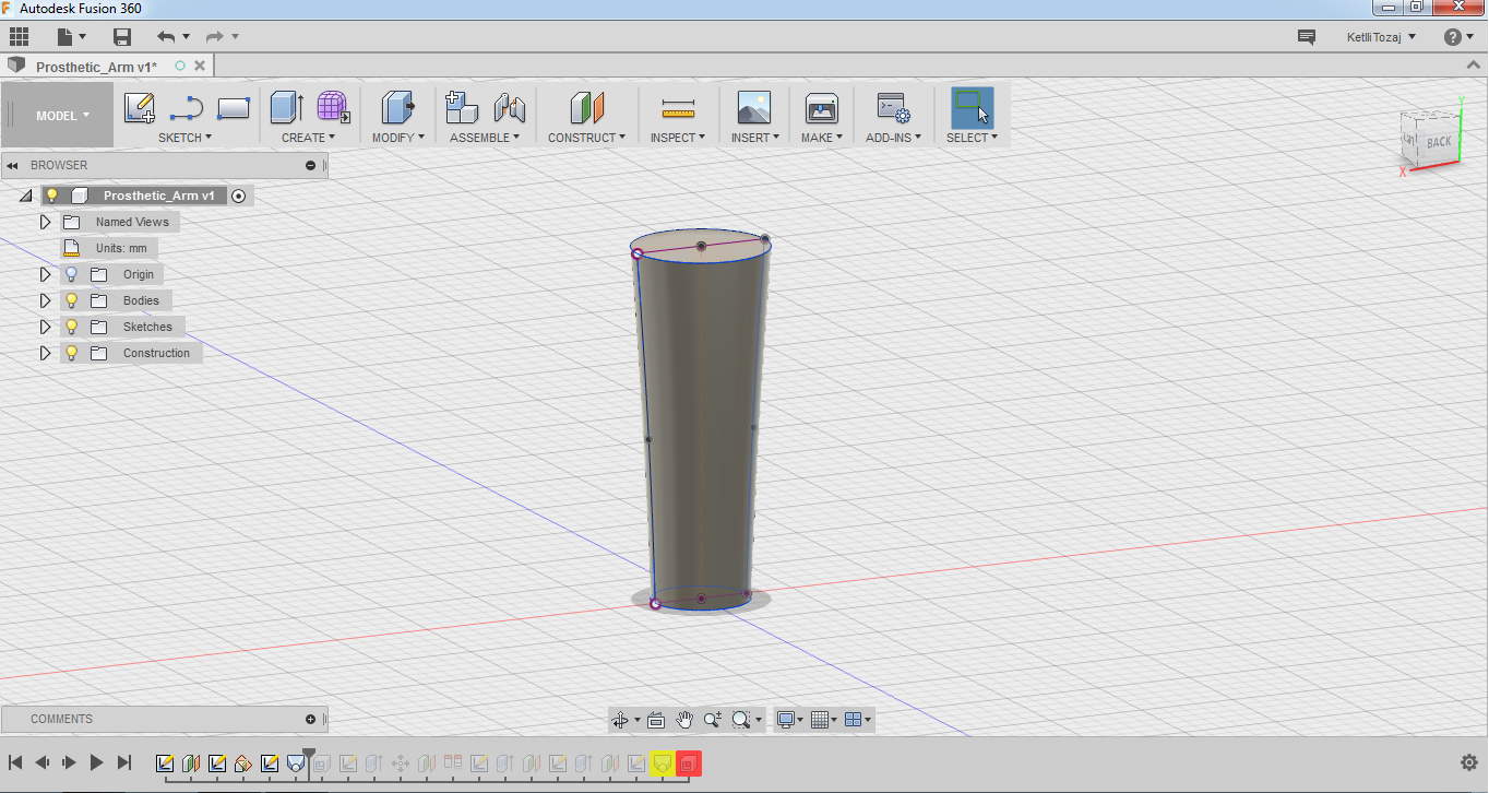
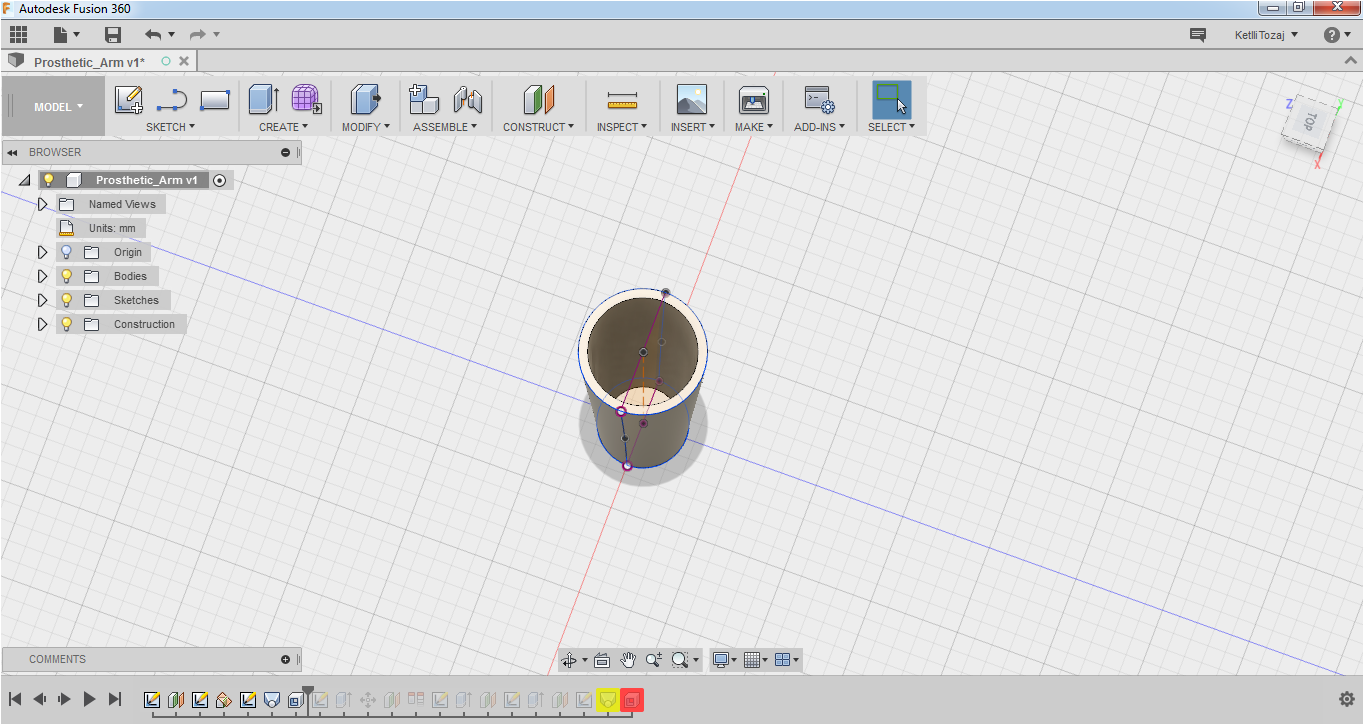
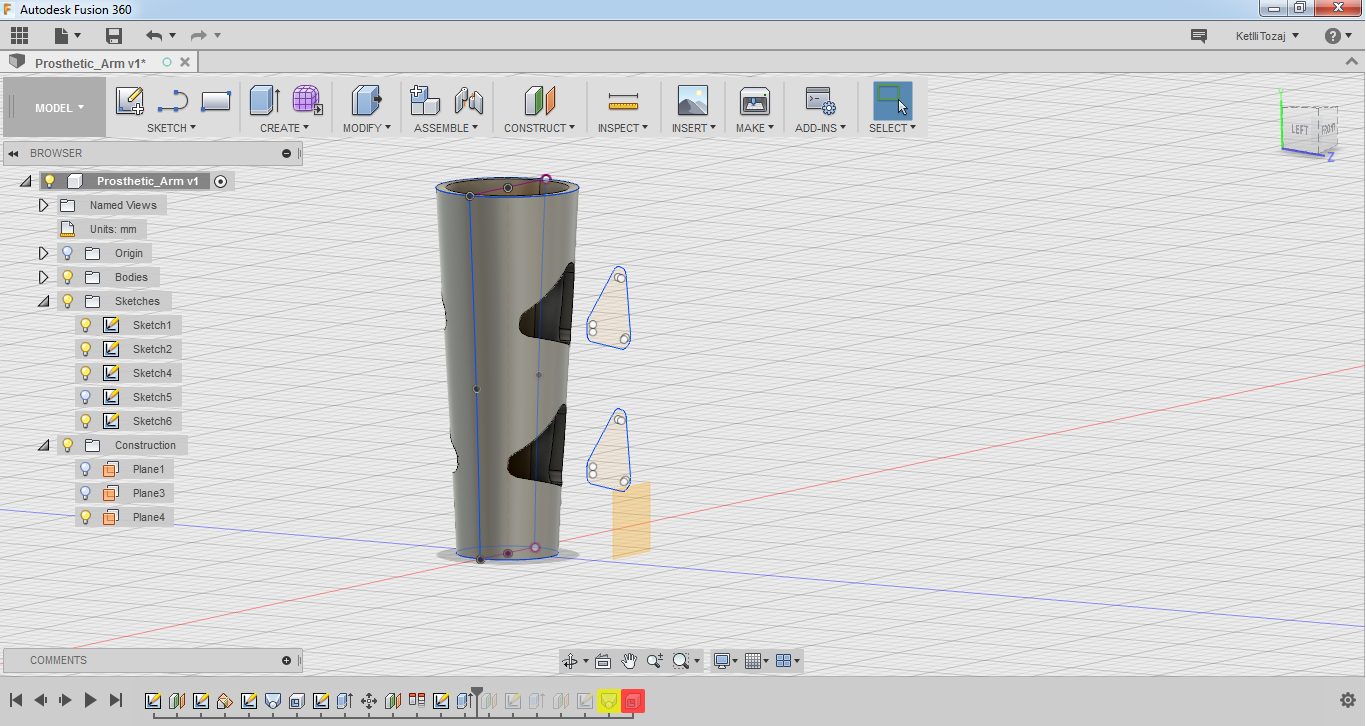
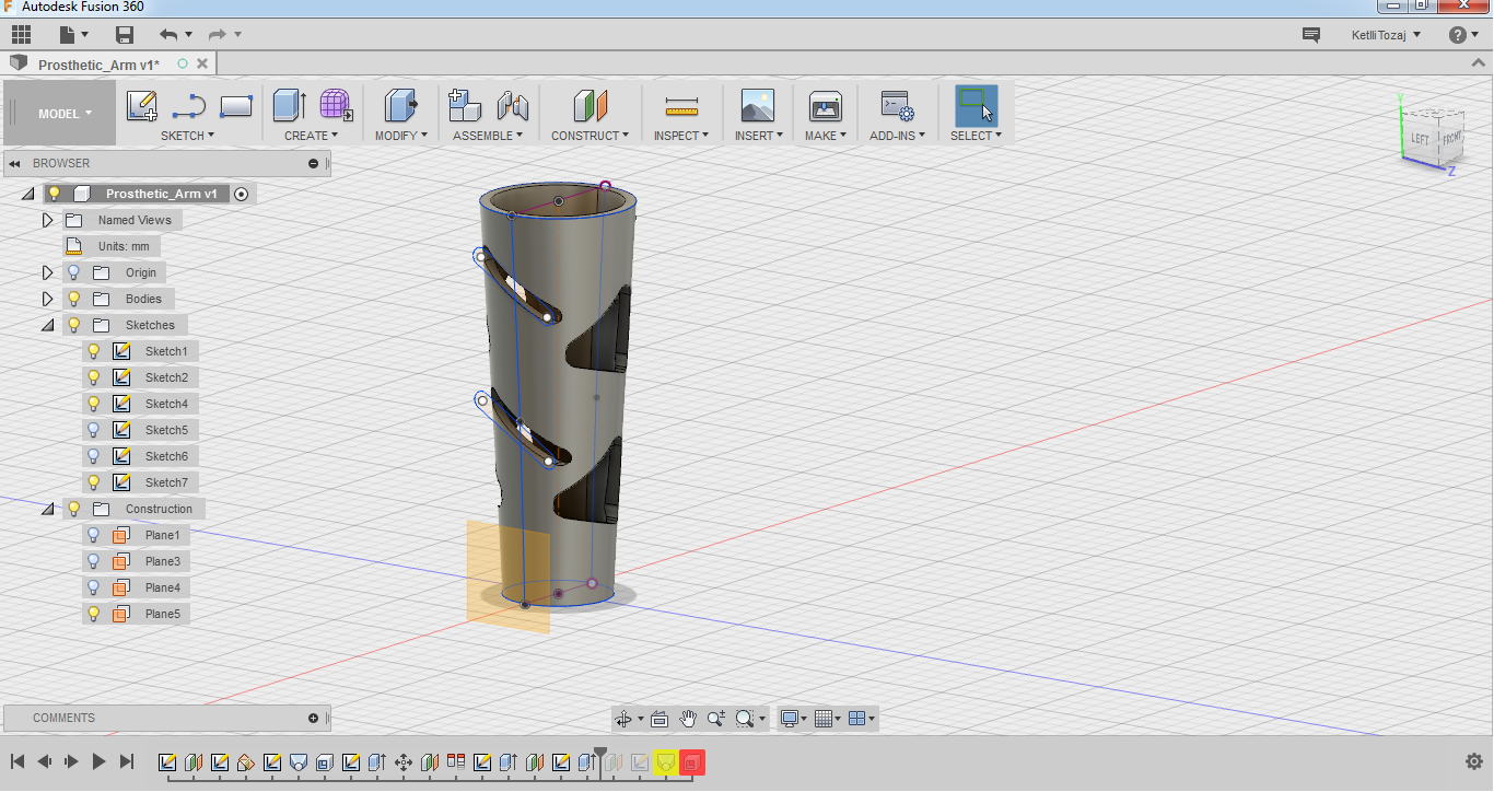
  • So, the end result looks like this:

    2D Design

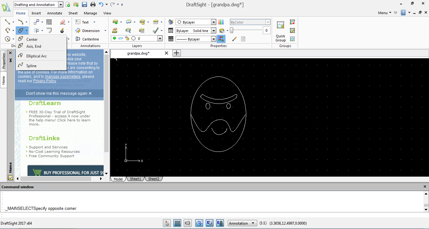
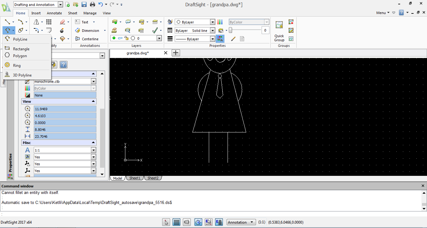
    For the creation of the 2D Design I used Draftsight. What I created for my 2D Design was a small design of a grandpa. It does not look so realistic but I tried my best considering my poor design skills.

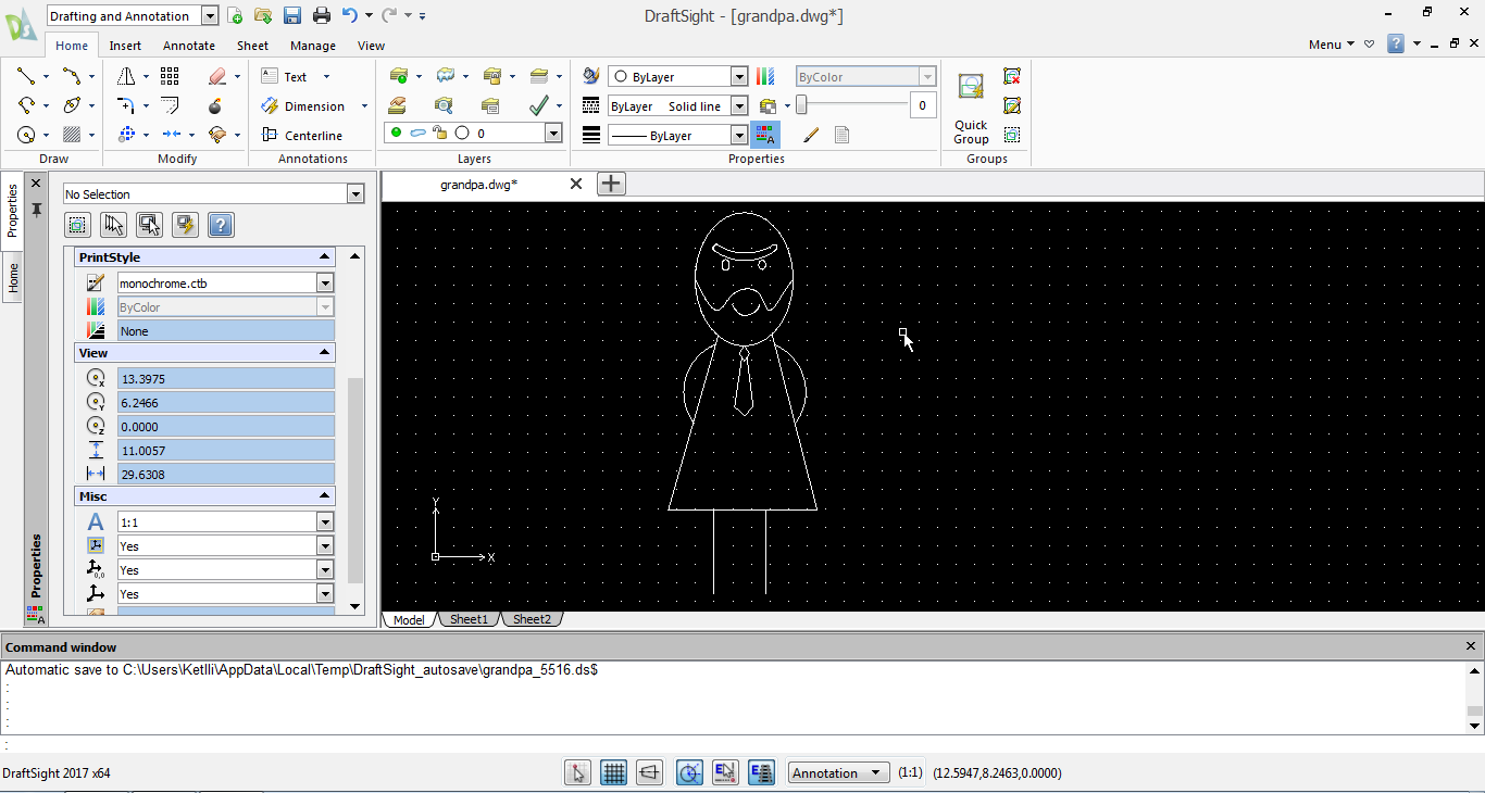
    For the head design of the grandpa, I used the ellipse for the shape of the face and the eyes, the spline for the smile and the shape of the beard and the arc and spline to create the eyebrows.

    For the body design, I used the polyline for the main body shape, the line for the feet, the rectangle and the polyline for the tie and lastly the arc and mirror for the hands. The first part of the tie is made with the rectangle. In order to change the orientation of it, I double-clicked on it and moved the corners with the mouse.

    Finally, my grandpa design looks like this:

    Downloads

    ProstheticArm.f3d | ProstheticArm.stp | Grandpa.dwg