Electronics Production
Production of the Board
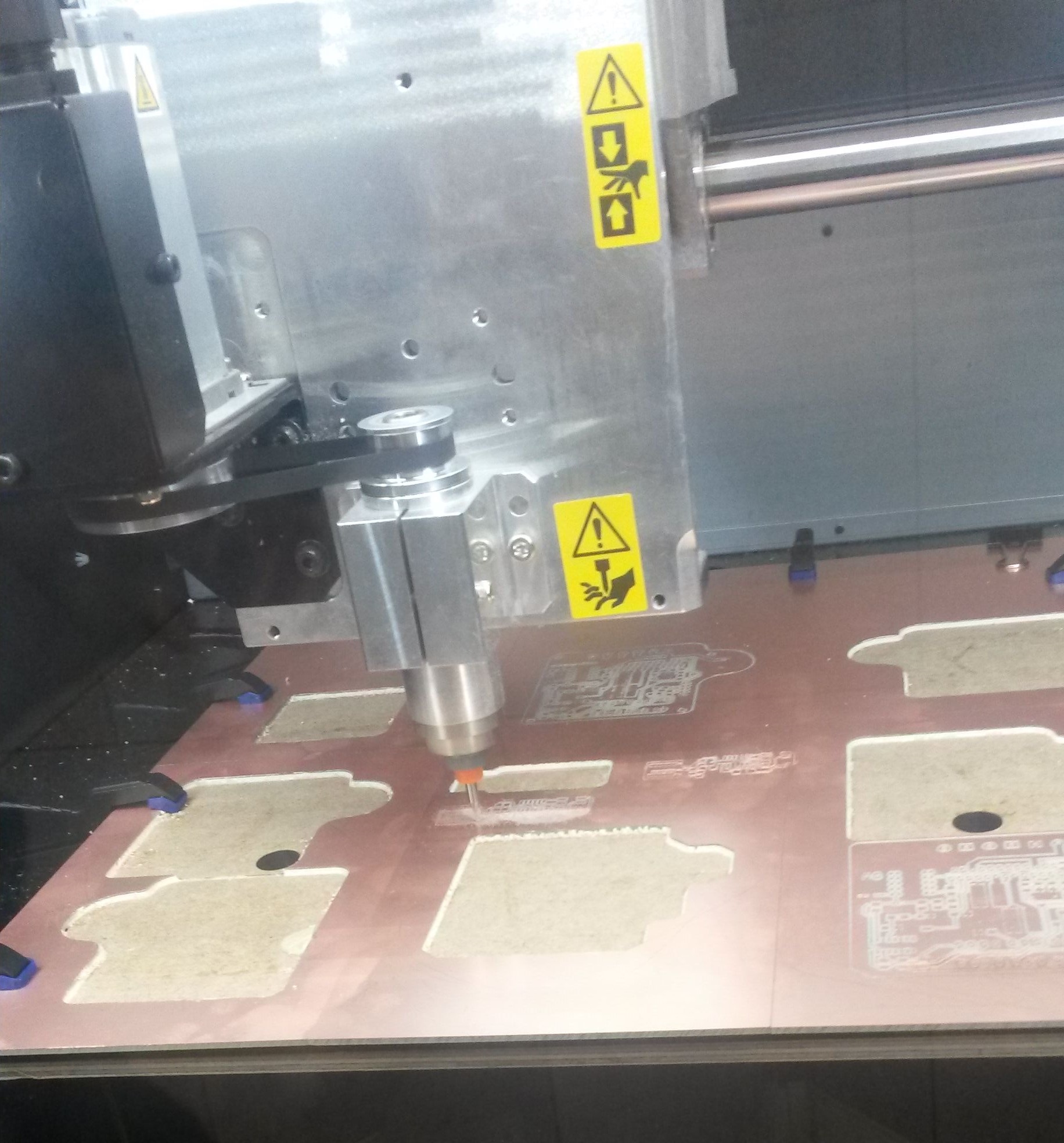
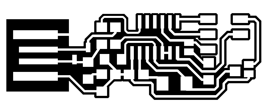
I produced the board with the Roland MDX40A milling machine. In order to do that we had to have two files. The one for the internal path of the PCB and the other one for the external. Luckily, those two files were given so all I had to do is use directly the machine.
During the process of production, I faced some problems between the connection of the computer and the machine and the machine itself. So, when the machine was getting stuck and connection between the computer and the machine was fine I had to do the following:
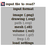
If problems between the connection occured all I had to do was to open the fabmoduleshtml5 (can be found on Dolphin > installed) and type in the command line sudo npm start
After having those in mind, we enter Fabmodules so that we can start the procedure of making the board. First, I made the internal path and then procceeded to make the external one. For the internal path I followed these steps:
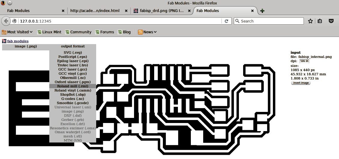
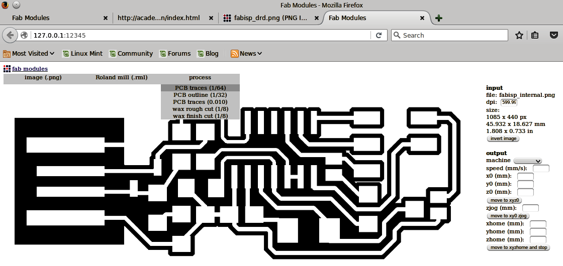
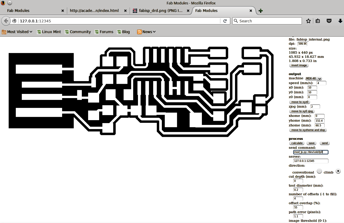
For the external path, we follow the exact same procedure while changing the tool in the machine to a 1mm diameter one and some settings to:
Soldering
For the soldering, we need the soldering iron which had to be set up in 320oC, the solder, some tweezers and maybe some desoldering copper and vacuum. In order to solder the traces effectively, I keep the iron tip a few senconds on the traces (note that if the iorn has a fine tip, we place it horizontally), and then add a little bit of soldering and we pull the tip away. After getting this equipment, I had to use get the parts needed to make the board. The parts needed were:
In order to solder the board, I followed the schematic below and the sample board of our instructor.
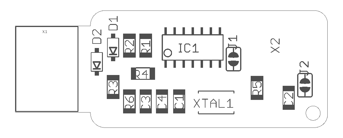
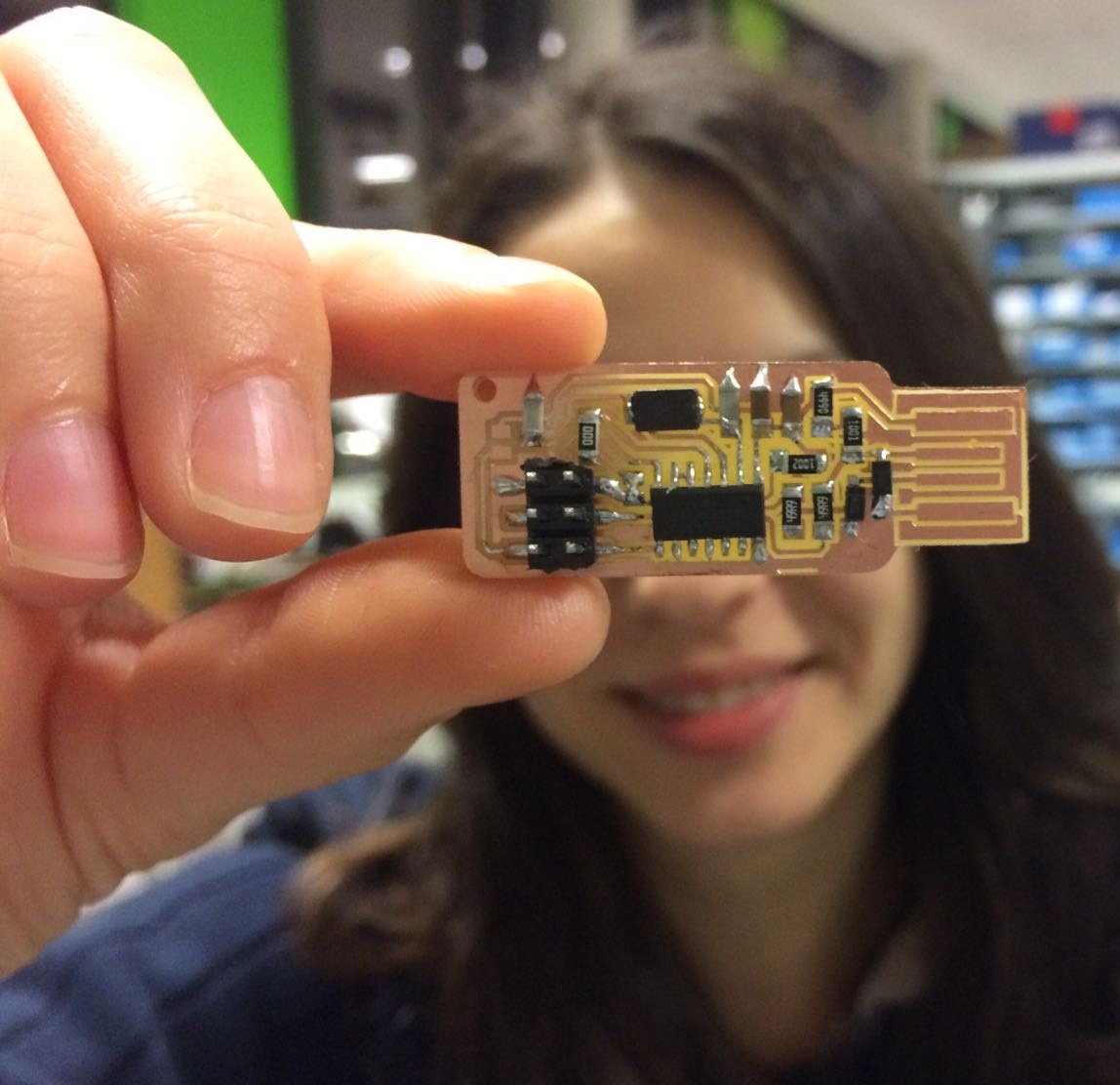
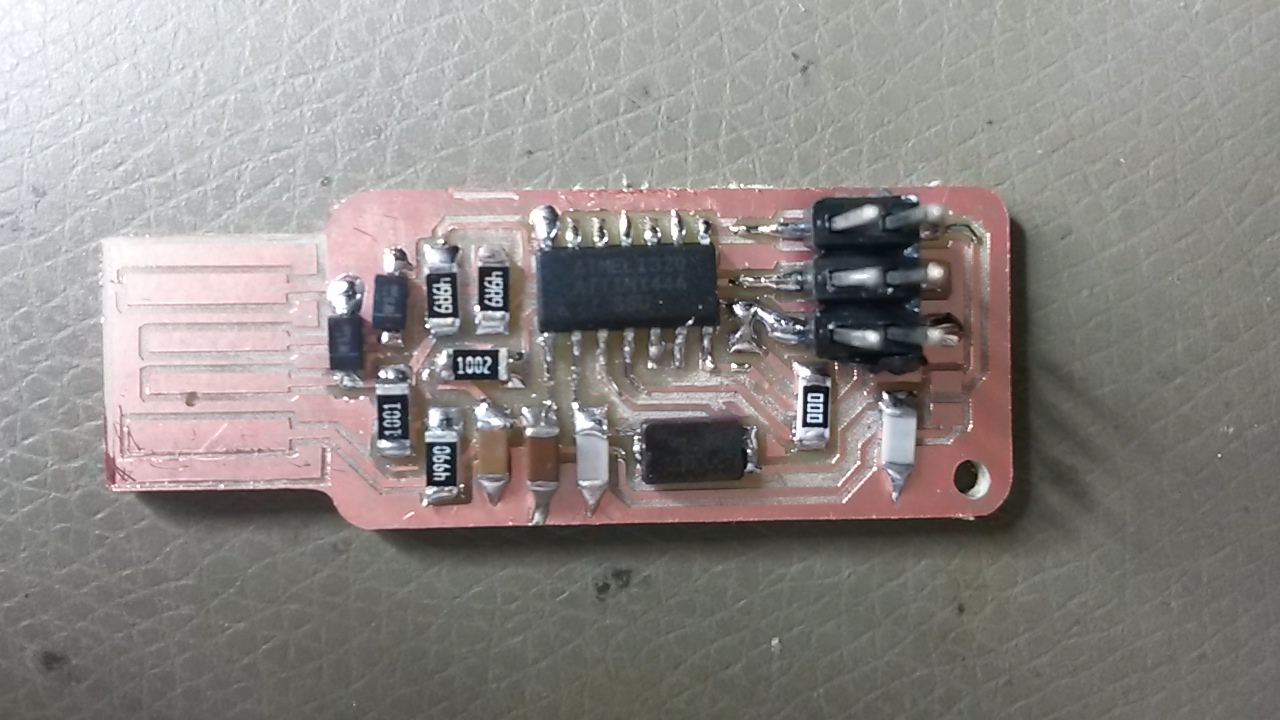
The soldered board, finally looked like this:
An important note here is not to forget to solder jumper 1 (J1) in order for us to be able to program the board. After programming the board, when we want to use it, then we can desolder it. Also, jumper 2 (J2) is recommended not to be soldered unless we want to power the board from an external power supply.
Programming the PCB
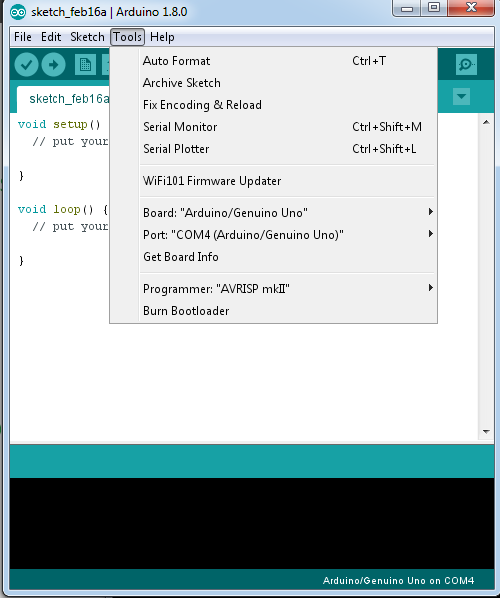
At first, I connected the Arduino to my pc, I opened the Arduino IDE, and chose the right board and port of my connected Arduino under tools.
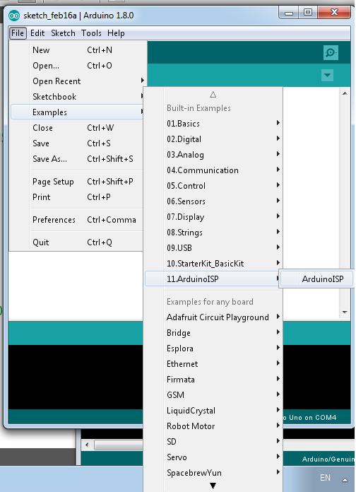
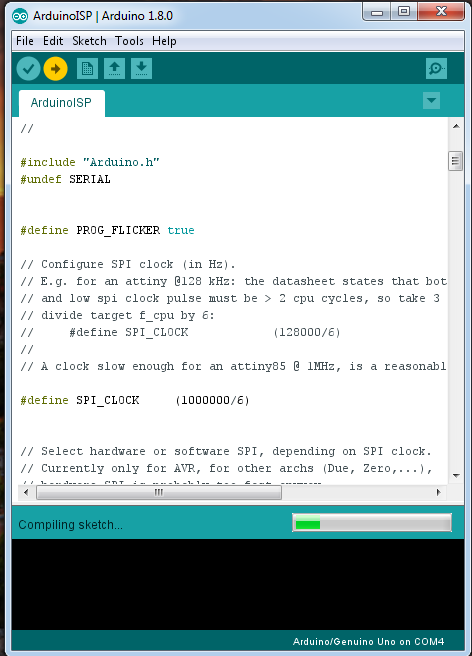
After I chose the right port and board, I found the program ArduinoISP and I uploaded it to my Arduino.
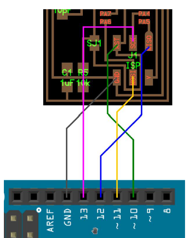
I disconnected my Arduino from the computer and I connect it with the FabISP following the schematic below:
After connecting the ISP with the Arduino, we connect the Arduino again. I downloaded firmware.zip and unzip-ed it to the desktop so that I have easier access to it. Now, in this step I had a problem. As I use Windows, the programming of the board was challenging. I firstly tried to use this manual for windows but it was unsuccessful. So, after that I found Cygwin, a linux based command line that can be used from the windows command line. In order to be able to use it properly, I followed this guide by also adding the nano command on the installation process. Even though the commands this time were recognised it was failing to execute them. So, after playing around with that, I decided to borrow the linux based computer of my colleague in order to program it. For the programming process of the Fab ISP on a linux based computer, I had to follow the following steps after entering to the terminal:
                                sudo apt-get install flex byacc bison gcc libusb-dev avrdude
                                sudo apt-get install gcc-avr
                                sudo apt-get install avr-libc
                                sudo apt-get install libc6-dev
                                 cd ~/Desktop
                                 wget http://academy.cba.mit.edu/classes/embedded_programming/firmware.zip
                                 unzip firmware.zip
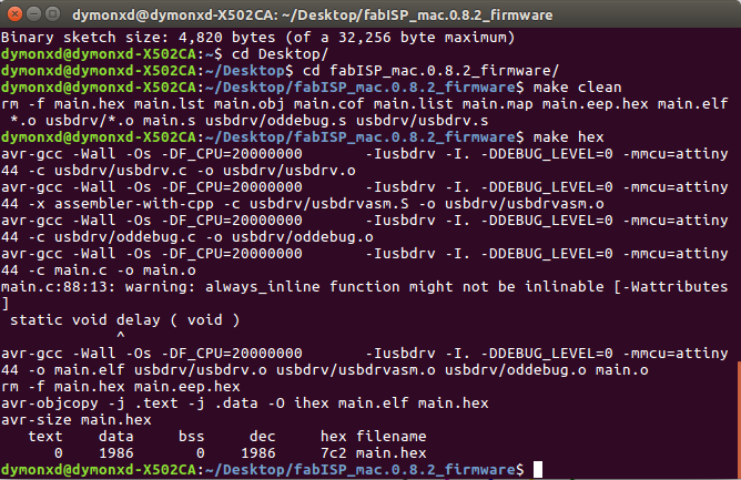
                                make clean
                                make hex
nano Makefile
When I entered the Makefile, I commented the following line by using # in front of it:
#AVRDUDE = avrdude -c avrisp2 -P usb -p $(DEVICE)
And I typed underneath it the following:
AVRDUDE = avrdude -c stk500v1 -P /dev/ttyACM0 -b19200 -p $(DEVICE)
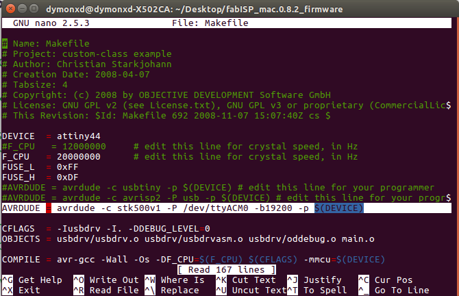
After doing that, I exit the file by pressing CTL+X, I pressed "y" for saving the file and enter for not renaming the file.
                                make fuse
                                make program
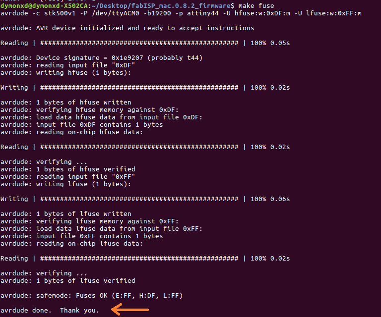
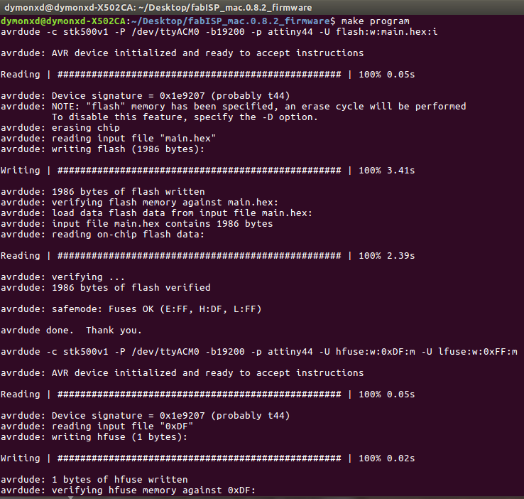
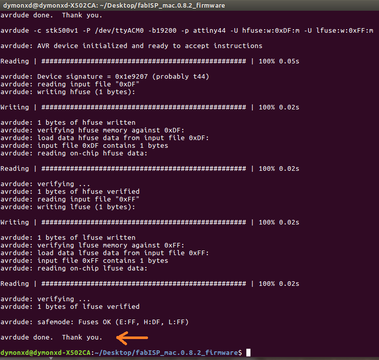
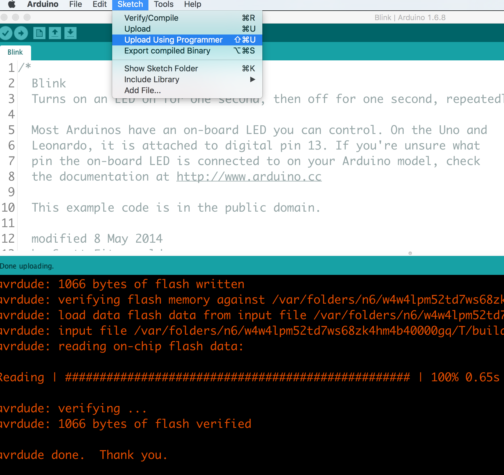
An important note here is that if we are successful, in the end of the executing of each command we have to see the phrase "avrdude done. Thank you.
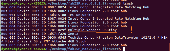
lsusb
Additions
In the upcoming weeks, I did not use the fabISP to program any of my boards and I had to do it, I am adding that part here. So, I programmed the board of the Output Devices week. The program is simple. I just made the LED blink. I made that using two methods. The first one was through the Arduino GUI and the other one was through the command line.
But before doing anything, I connected the fabISP to my modified satshakit using the sketch below and made sure to desolder jumper 1 (J1) so that I will actually be able to program the board:
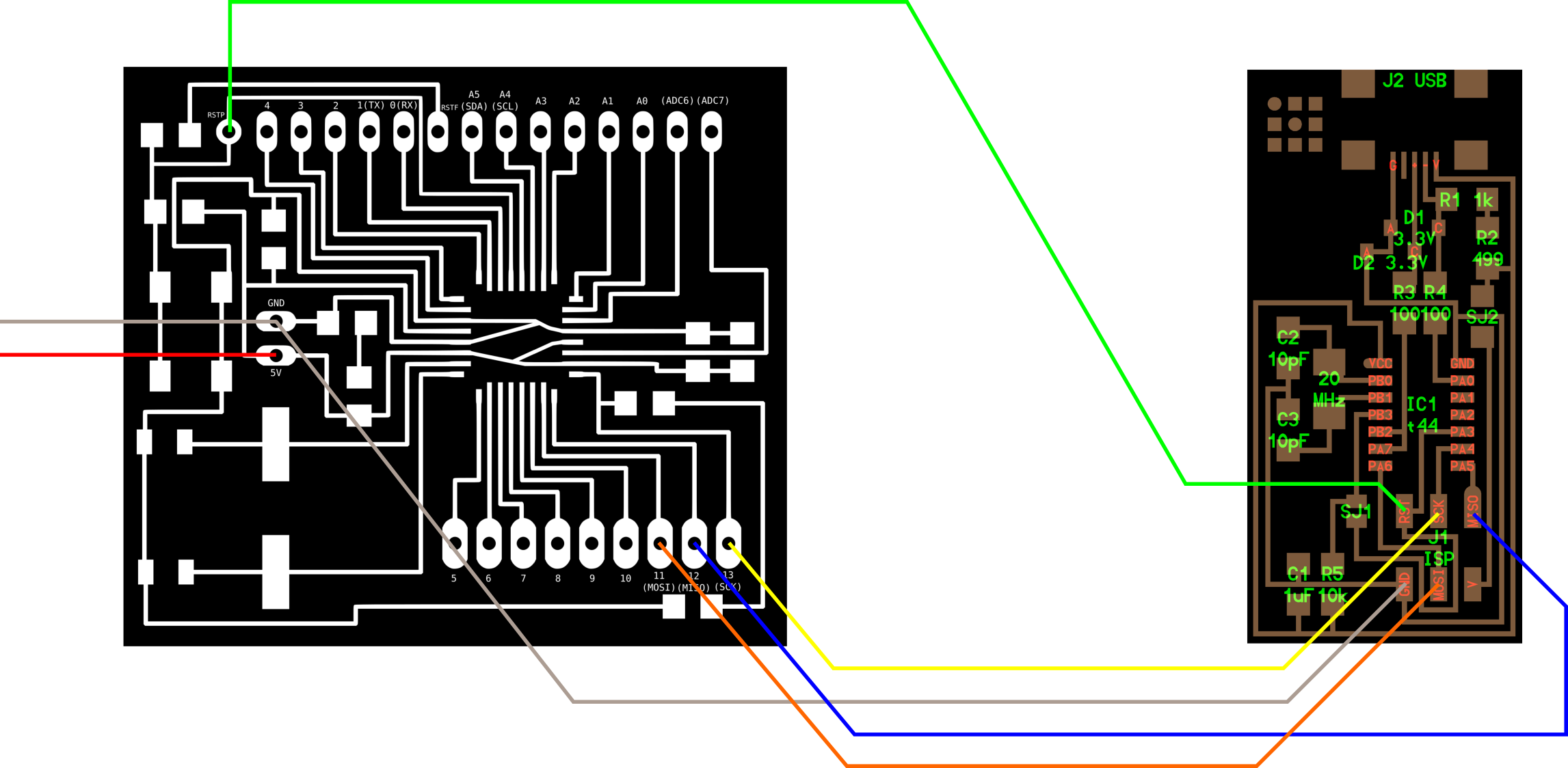
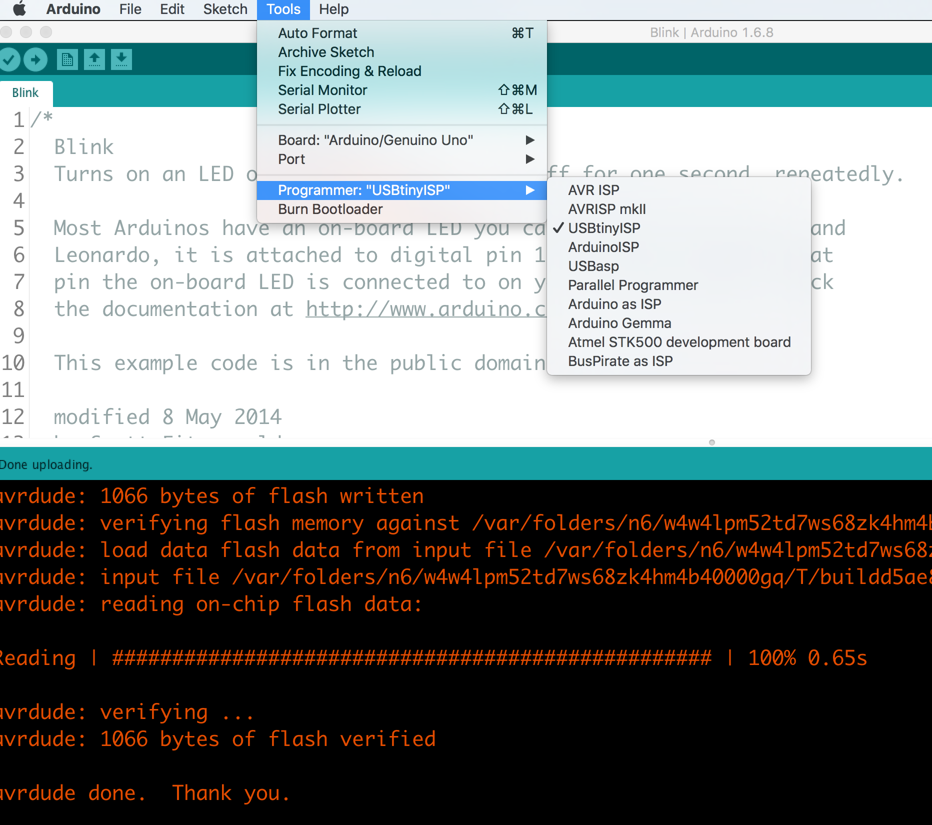
So, after connecting the fabISP to the board and powered the board with the use of the ftdi cable, I was ready to program it. Via the Arduino GUI, I opened the blink example and changed the delay to it. Then, I chose the right port, the Arduino UNO as the board and the USBtinyISP as the programmer. I uploaded using programmer and it worked!!
Below, there is the video of the board working accordingly.
Now, the hard way via the command line. To program the board I need the following:
As the computer that I used, had already the necessary libraries, all I had to do was to modify the makefile so that it can program the ATmega328p. But, just in case for next time the steps for installing the necessary libraries are:
sudo apt-get install flex byacc bison gcc libusb-dev avrdude

sudo apt-get install gcc-avr
- type "y" when asked to do so by your system

sudo apt-get install avr-libc

sudo apt-get install libc6-dev
The modifications that I made to the makefile so that it matches my MCU are also illustrated below:
PROJECT=blink
SOURCES=$(PROJECT).c
MMCU=atmega328p
F_CPU = 16000000

CFLAGS=-mmcu=$(MMCU) -Wall -Os -DF_CPU=$(F_CPU)

$(PROJECT).hex: $(PROJECT).out
	avr-objcopy -O ihex $(PROJECT).out $(PROJECT).c.hex;\
	avr-size --mcu=$(MMCU) --format=avr $(PROJECT).out

$(PROJECT).out: $(SOURCES)
	avr-gcc $(CFLAGS) -I./ -o $(PROJECT).out $(SOURCES)


program-fabISP: $(PROJECT).hex
	avrdude -p m328p -P usb -c usbtiny -U flash:w:$(PROJECT).c.hex
The modifications made to the makefile were on the third line the name of the MCU, on the fourth line the frequency of the crystal, and on the last line the code of the atmega328p which is m328p.
So, after I did all that, I just created a new file with the name blink.c and after that was ready I just compiled it. The C code is shown below:
#include  <avr/io.h>
#include  <util/delay.h>

#define F_CPU16000UL
#define LED_YELLOW_PORT PORTB

int main (void){

  DDRB = 0xFF;  //set PORTA for output


  while (1){

      LED_YELLOW_PORT = 0b00100000;  //set PORTA.7 high

      _delay_ms(1000);

      LED_YELLOW_PORT = 0b00000000;  //set PORTA.7 low

      _delay_ms(1000);
  }
}
To compile the program I placed the C code in the same folder with the makefile. Then using the command line I entered that folder and used the command make program-fabISP to compile the program. And it worked!!! :)
Below it the log of the compilation of the program:
make program-fabISP
avr-gcc -mmcu=atmega328p -Wall -Os -DF_CPU=16000000 -I./ -o blink.out blink.c
avr-objcopy -O ihex blink.out blink.c.hex;\
	avr-size --mcu=atmega328p --format=avr blink.out
AVR Memory Usage
----------------
Device: atmega328p

Program:     180 bytes (0.5% Full)
(.text + .data + .bootloader)

Data:          0 bytes (0.0% Full)
(.data + .bss + .noinit)


avrdude -p m328p -P usb -c usbtiny -U flash:w:blink.c.hex

avrdude: AVR device initialized and ready to accept instructions

Reading | ################################################## | 100% 0.00s

avrdude: Device signature = 0x1e950f (probably m328p)
avrdude: NOTE: "flash" memory has been specified, an erase cycle will be performed
         To disable this feature, specify the -D option.
avrdude: erasing chip
avrdude: reading input file "blink.c.hex"
avrdude: input file blink.c.hex auto detected as Intel Hex
avrdude: writing flash (180 bytes):

Writing | ################################################## | 100% 0.25s

avrdude: 180 bytes of flash written
avrdude: verifying flash memory against blink.c.hex:
avrdude: load data flash data from input file blink.c.hex:
avrdude: input file blink.c.hex auto detected as Intel Hex
avrdude: input file blink.c.hex contains 180 bytes
avrdude: reading on-chip flash data:

Reading | ################################################## | 100% 0.14s

avrdude: verifying ...
avrdude: 180 bytes of flash verified

avrdude: safemode: Fuses OK (E:FD, H:DE, L:FF)

avrdude done.  Thank you.
Below, it is a short video of the working example of above:
Downloads
The internal path of the board can be found here.
The external path of the board can be found here.
And finally, thhe firmware.zip can be downloaded as a zip file from here.
The makefile and the .c code of the program.
My hero shot