Computer Controlled Machining
Furniture Design
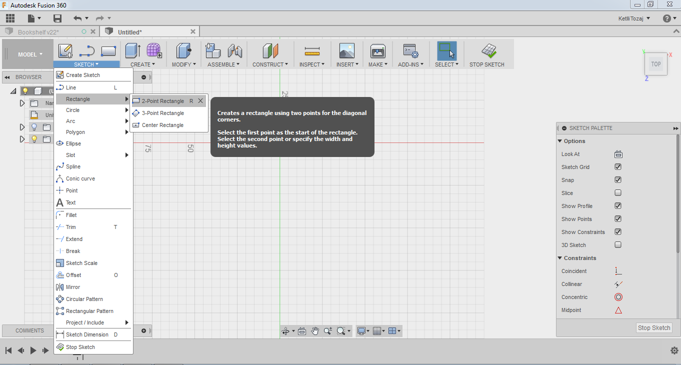
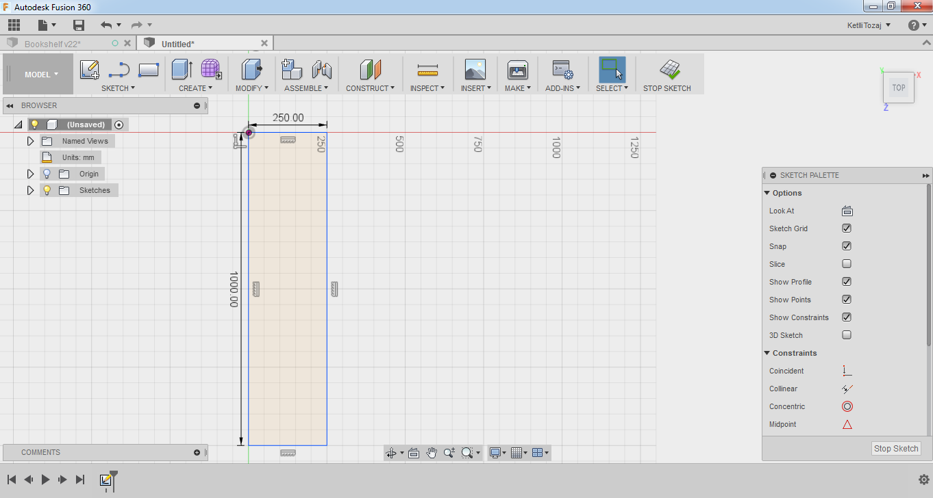
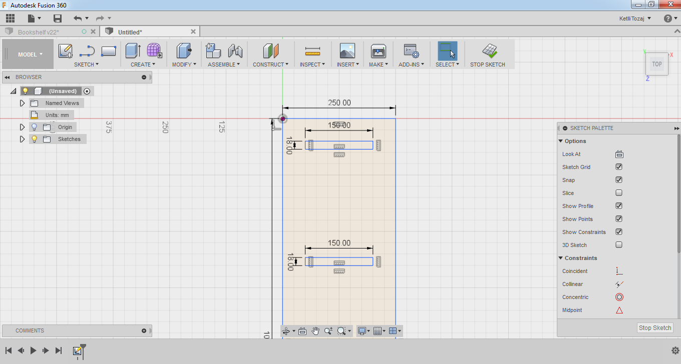
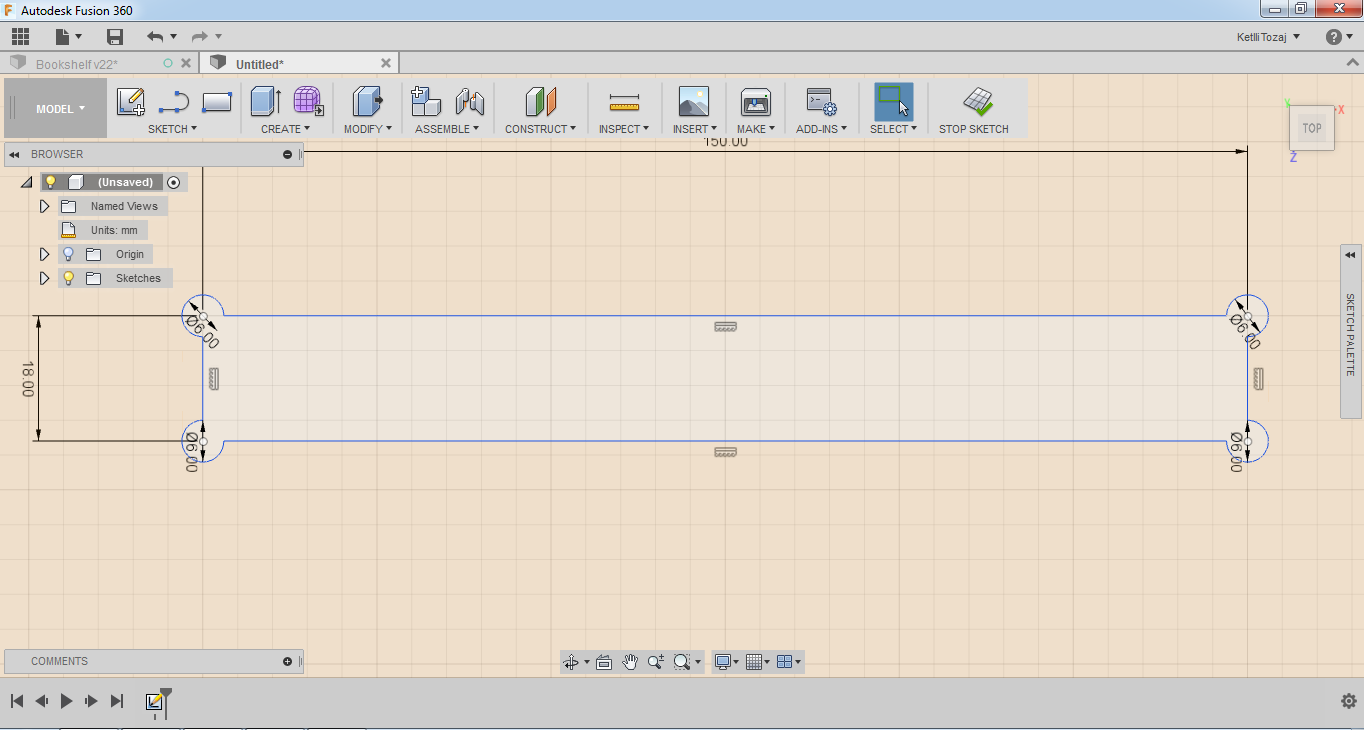
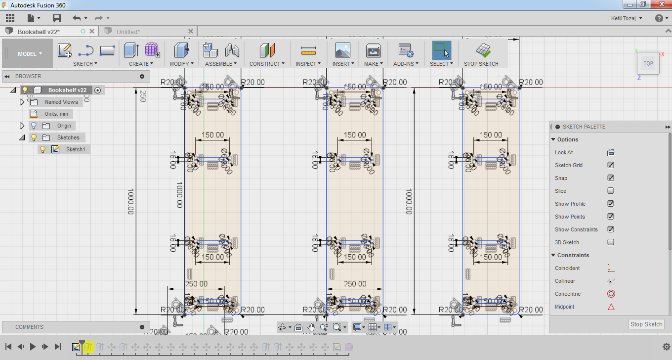
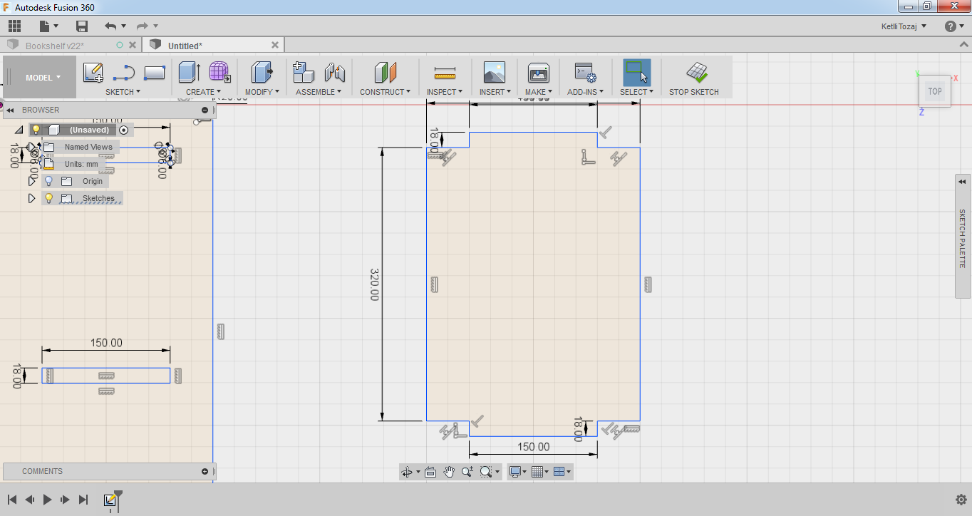
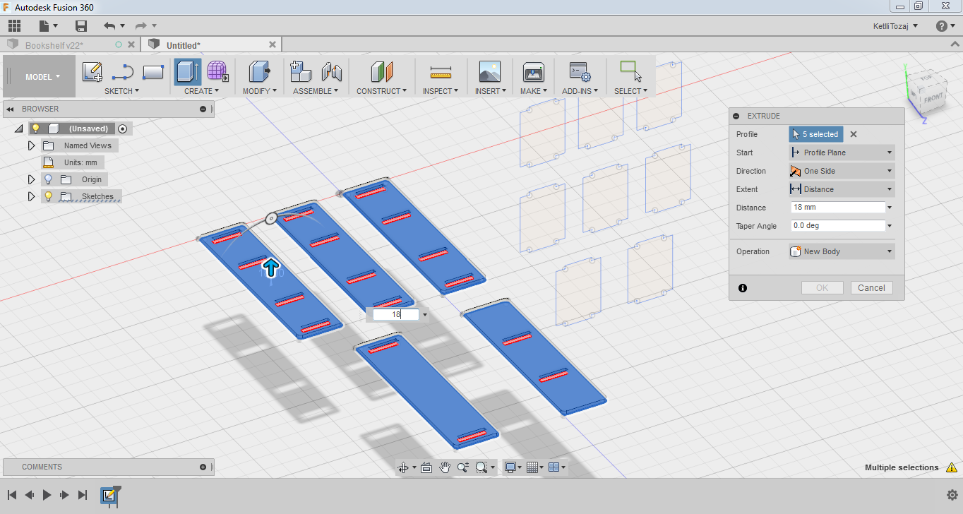
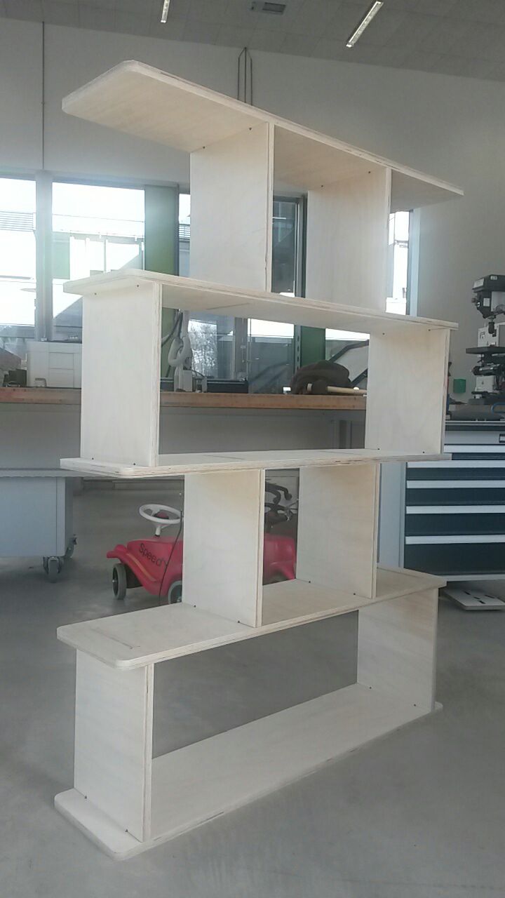
For my "Computer Controlled Machining" week I decided to make a bookcase. The first step for the making of the bookcase was the design of it. I designed the bookcase in Fusion 360. Initially, I made the design on sketch and then extruded everything by 18mm to see if everything fits in together and whether the design was the one that I had pretty much in mind. I used an 18mm thick sheet of wood for the making of the design. So, I started off sketching a rectangle with dimensions of 1000x250mm2 by selecting a 2-point rectangle under the sketch menu.
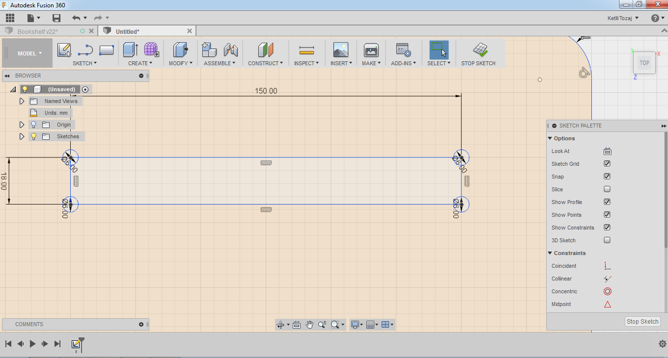
After making the rectangles, which would be the outer physical structure of my design, I started considering the fittings of my design. So, I drew constraints for the inner pockets of the design from the top and bottom of the rectangle.
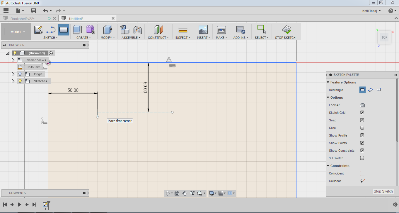
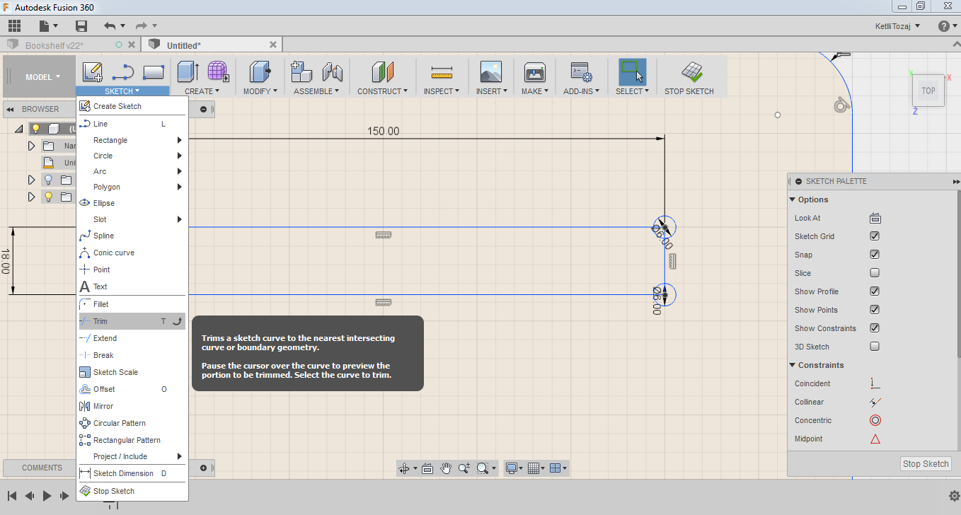
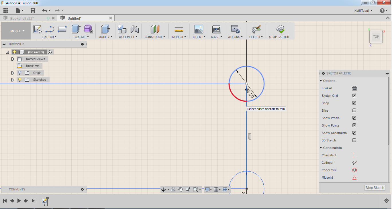
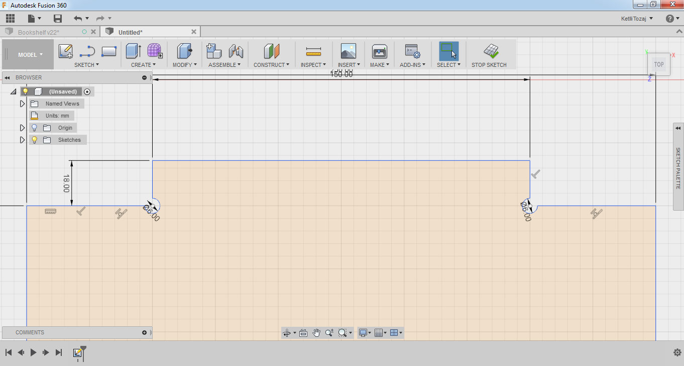
The problem with this design if I left it like this would be that it would not be able to make 90 degree angles. So, I had to create small circle pockets on each 90o inner angle. As the tool has a diameter of 4mm, I created circles of 6mm by pressing "C" on my keyboard. After designing the circles where necessary, I trimmed the parts that were not needed by using the trim tool under the sketch menu.
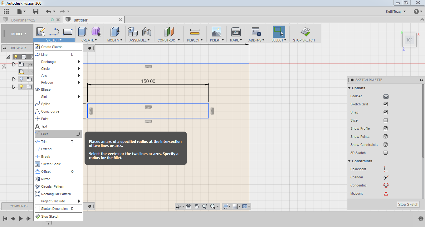
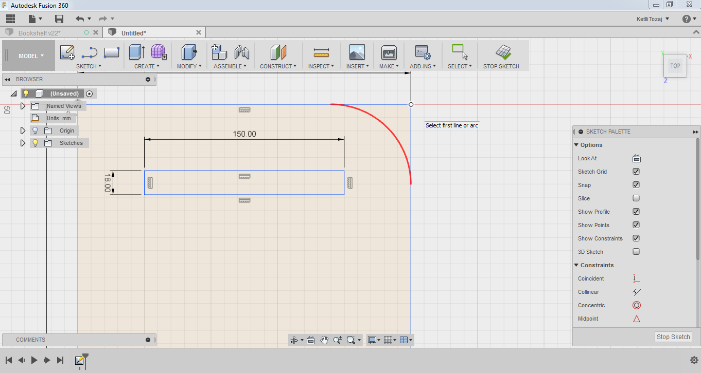
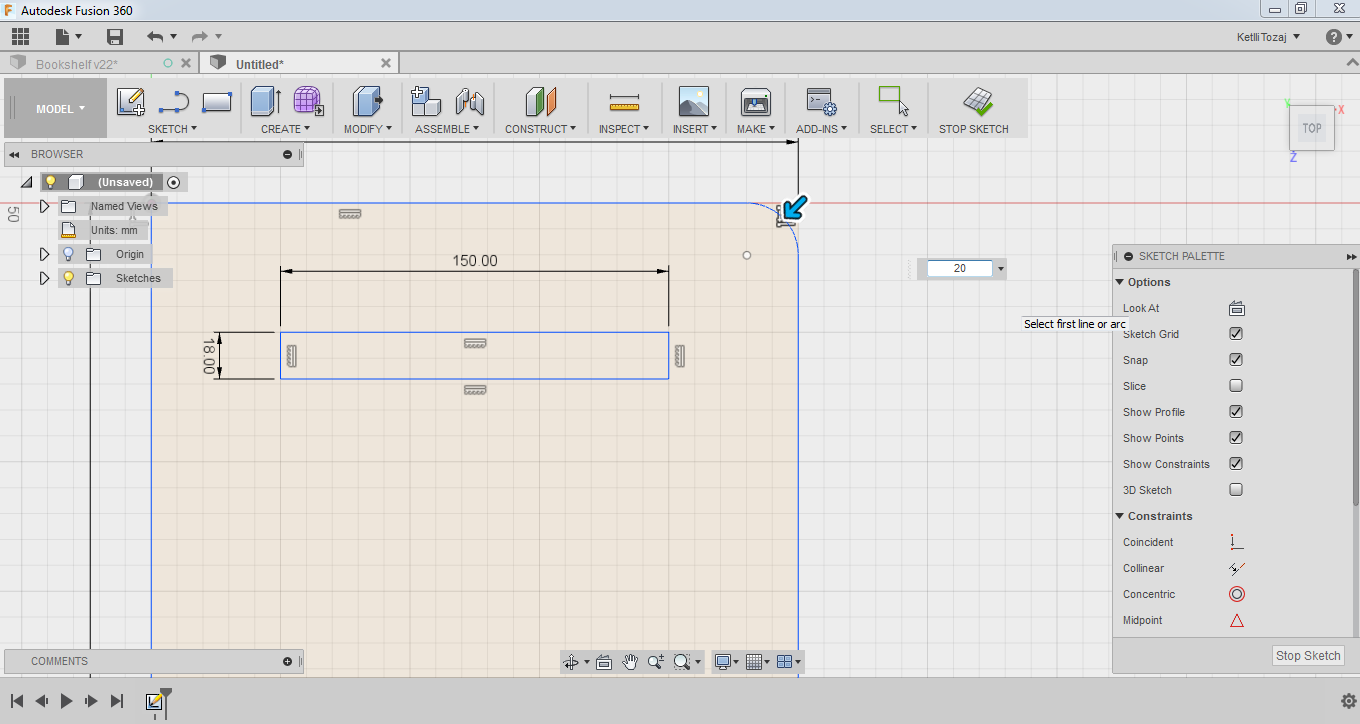
After having taken care of the inner pockets were the fittings would go, I wanted to create a small fillet on the edges of my design. To do this, I selected the fillet function under the sketch menu on the model environment as before and entered the value that I wanted my fillet to have. After finishing this, I copy pasted my design four more times in order to create every horizontal part of my design as they are similar. I had three horizontal pieces of exactly the same design. The top and bottom shelf of my bookcase were missing two out of the total four pockets that the middle ones have, so all I did was to delete two of the four that I did not want.
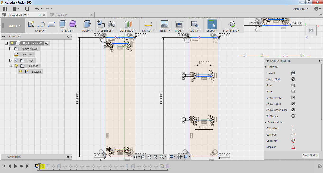
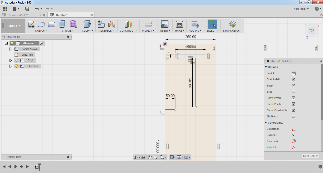
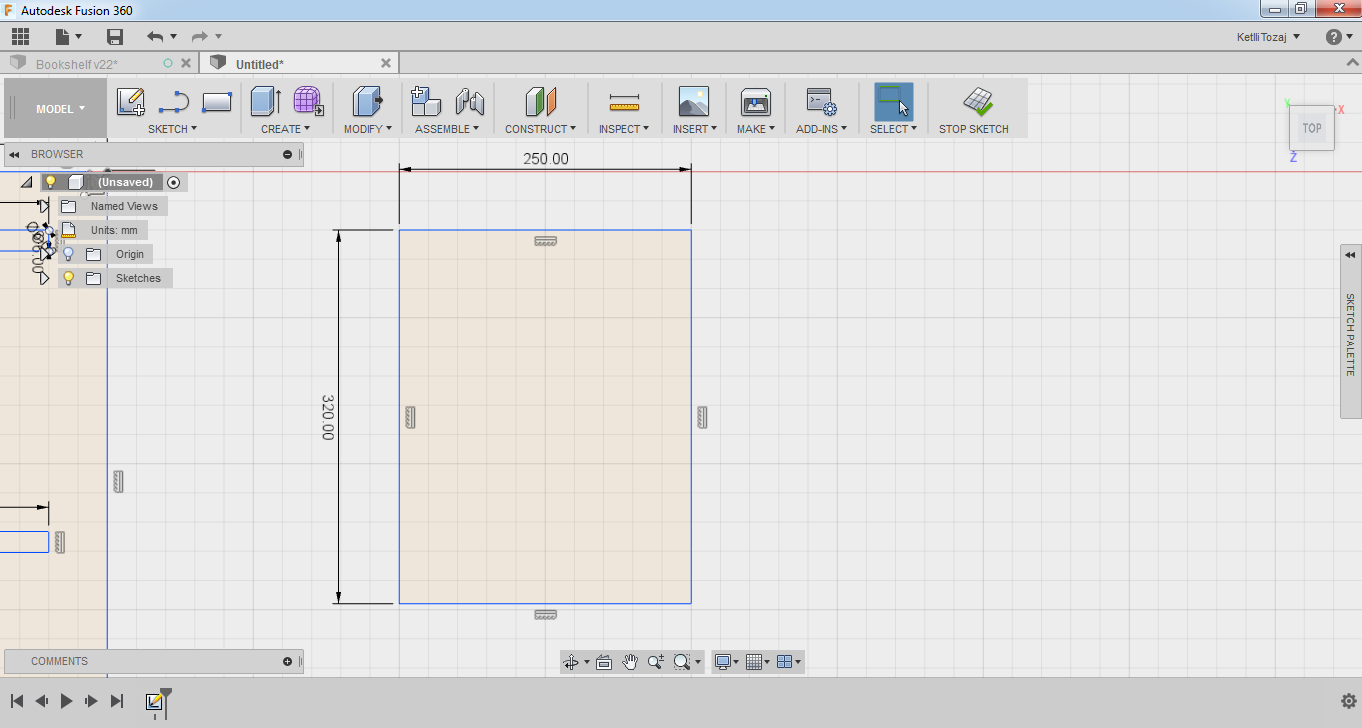
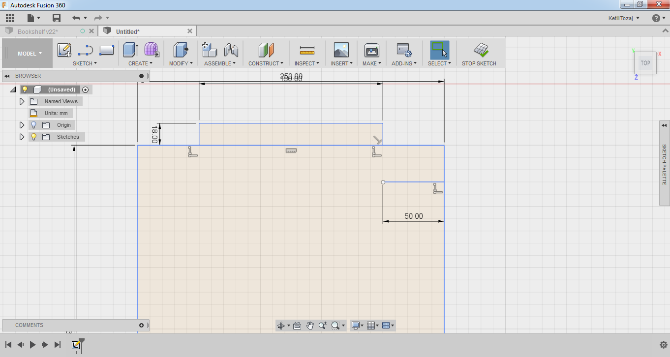
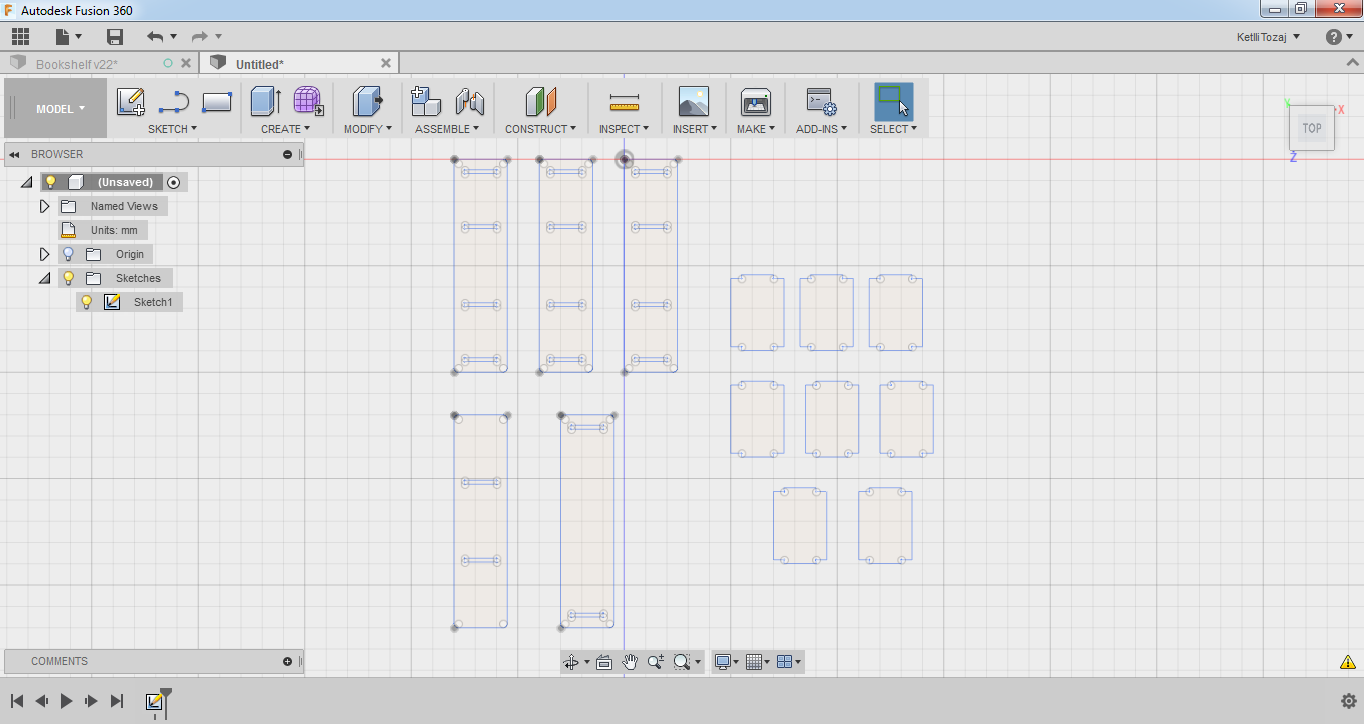
After creating the horizontal parts of my bookcase, I had to create the intermediate vertical parts, the fittings. Again, as before I started out with a rectangle by selecting the 2-point rectangle under the sketch menu with the dimensions of 250x320mm2. After creating the main body with the rectangles, I made the fittings by using the line under the sketch menu. The dimensions of the fittings are 18mm (the thickness of the material) by 150mm with a constraint of 50mm from the one edge of the main body of the fitting. After creating the fittings, I trimmed the useless lines by using the trim tool as before and made pocket circles for the inner 90o angles with the same parameters as before (6mm diameter). After finishing this design as well, my design was ready to be cut. I copy pasted the vertical design of my system, seven more times and I stopped the sketch.
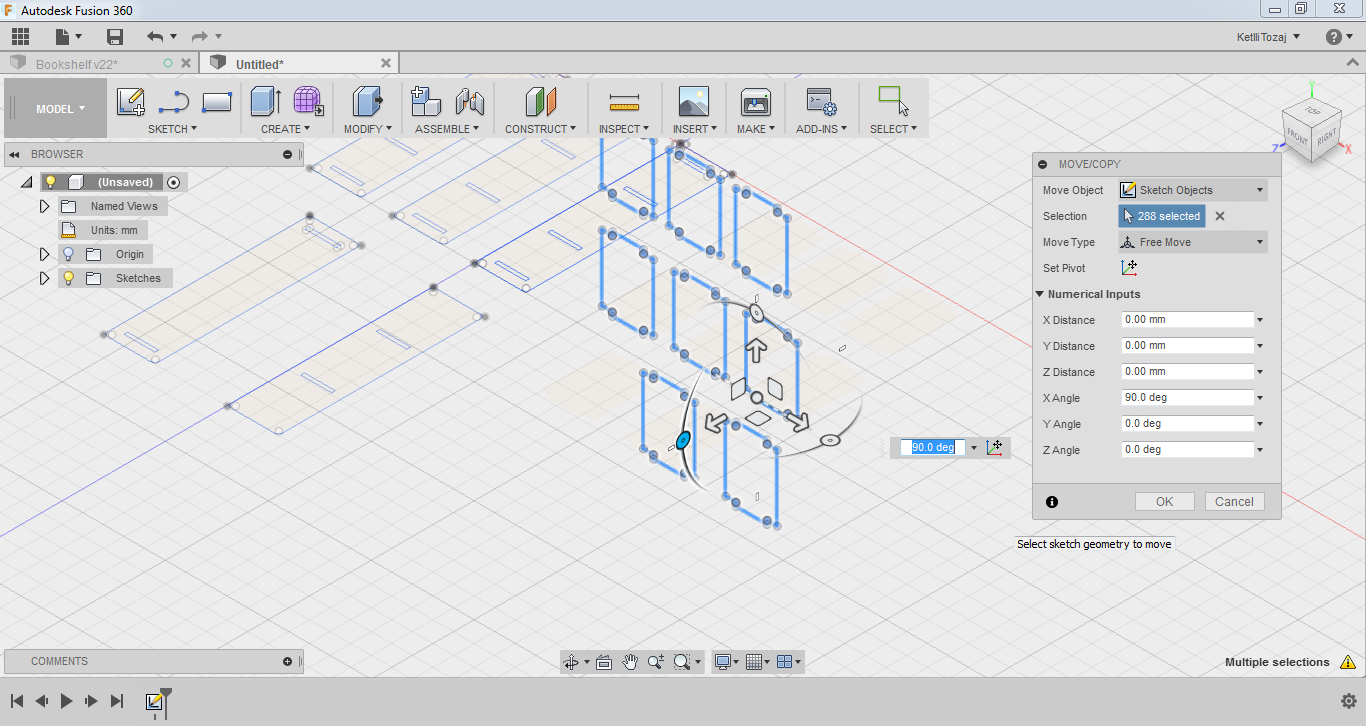
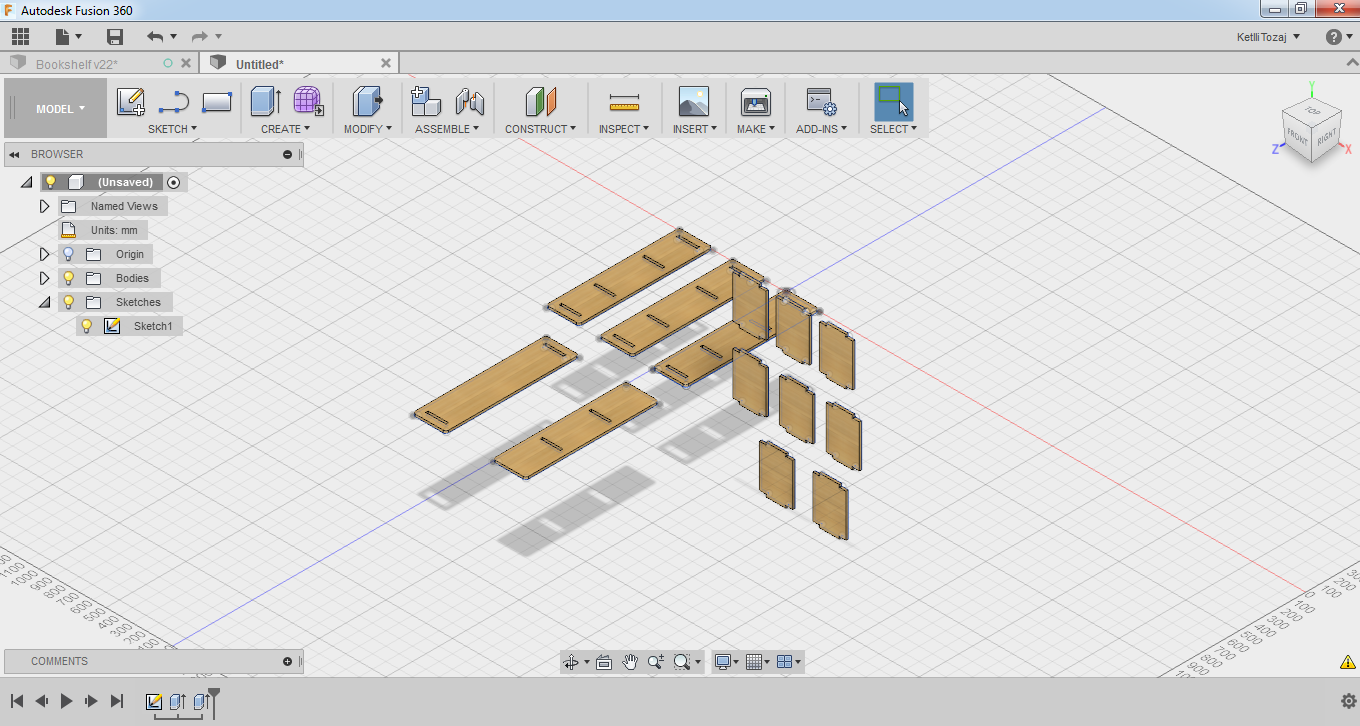
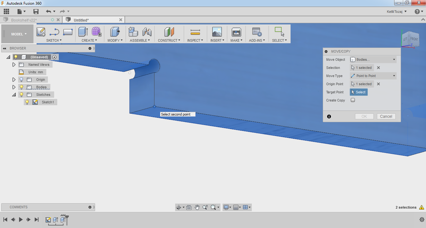
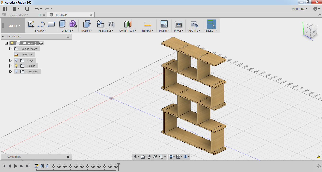
Now, after my design was all good, I extruded the parts and then assembled them together to see if it will look like I want. So, I extruded every part by the thickness of my material which is 18mm, I rotated the vertical parts of my design by 90o and then I used the move function to assemble tha parts together. On the move function, I chose the point to point function of it.
Machining
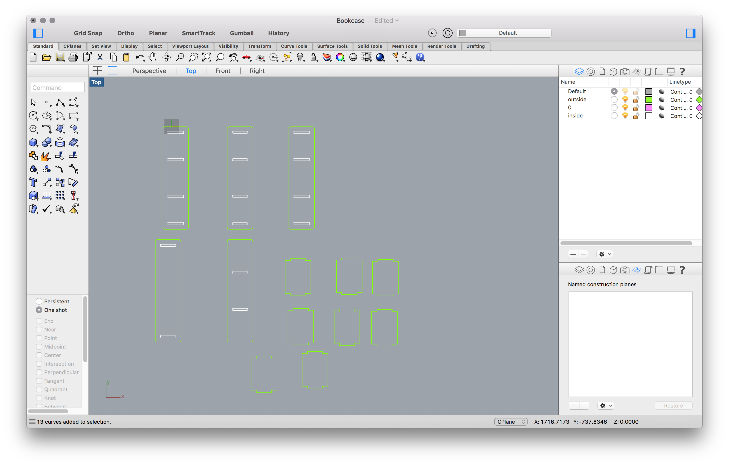
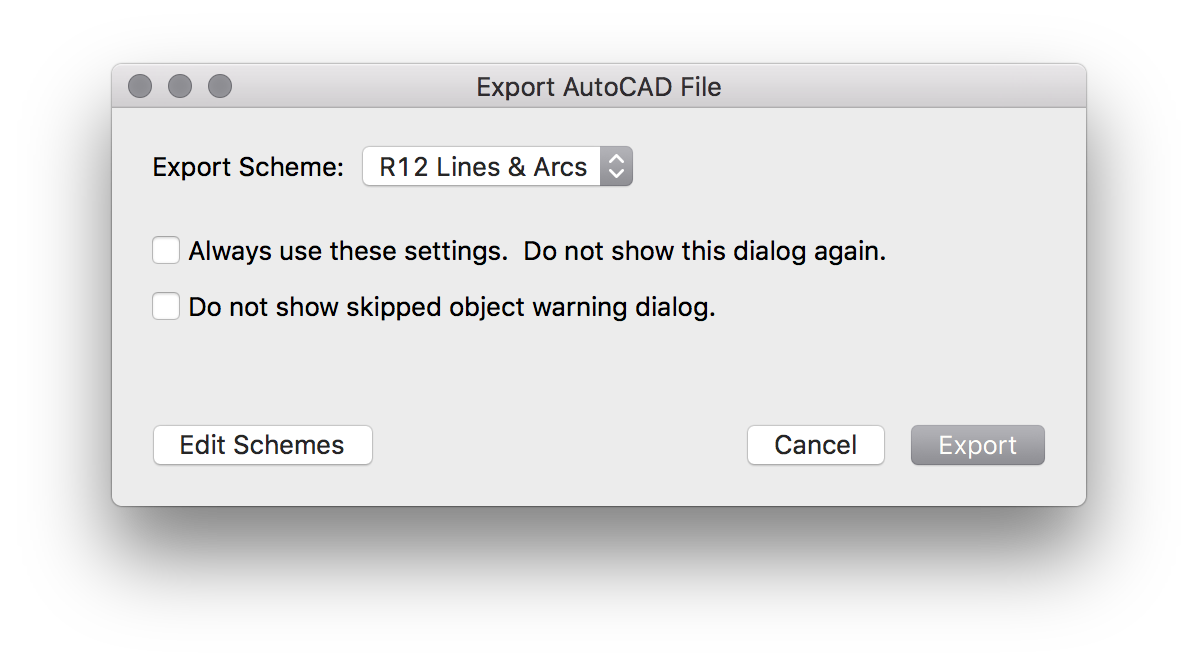
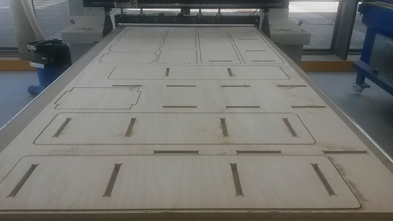
After my design was ready I proceeded to the cnc machine in order to cut it. I exported my design as a .dwg file from fusion and then I inserted my design in Rhino. Having inserted my design, I set different layers for the inside and outside cut by setting different colours on each layer. Always we have to set the inside cut as the first job before the outside because the design should stay stable. After setting the layers, I exported the AutoCAD file as "R12 lines and Arcs" and I was ready to insert it to the program of the machine and start the cut procedure.
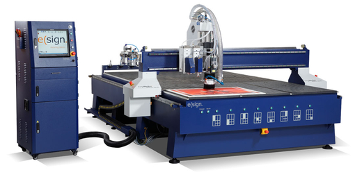
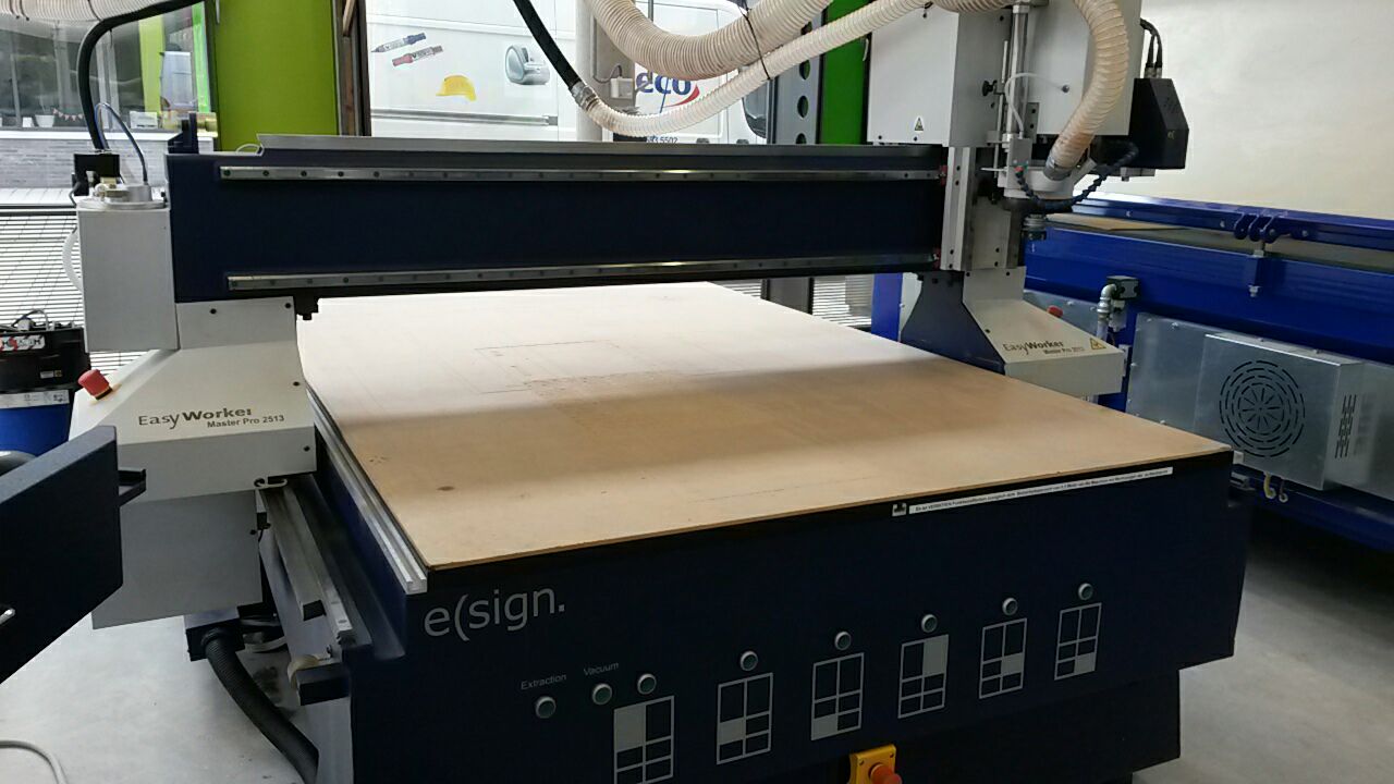
The CNC machine that was used was EasyWorker MasterPro 2513. Its working area is 2600x1400x300 mm3 and it has a vaccuum table.
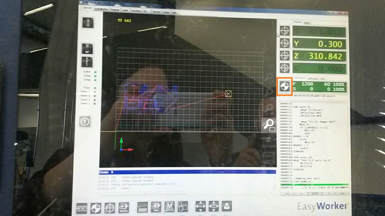
First thing to do was to clean the cover sheet on the vaccuum table. After we placed the material on the bed then we opened the cnc software. First, I homed all the axis. Firstly, I homed the x and y-axis. To do that, I pressed the small laser icon in the software and then navigated through the bed using the just the arrow keys for slow movement and shift+the arrow keys for a fast movement. To home the z axis a height sensor is used. I homed the z axis by placing the height sensor on the cover sheet. So, I brought the needle of the machine as close as possible near the height sensor and then on the automatic tab I pressed F11 for the user menu. Then, I pressed F2 for the automatic calibration. After homing each axis we would zero it in the software as well.
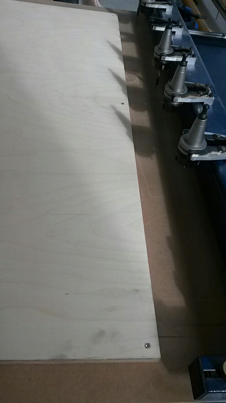
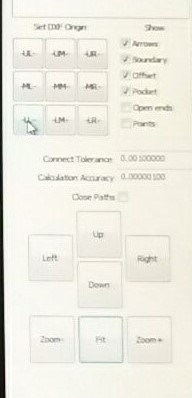
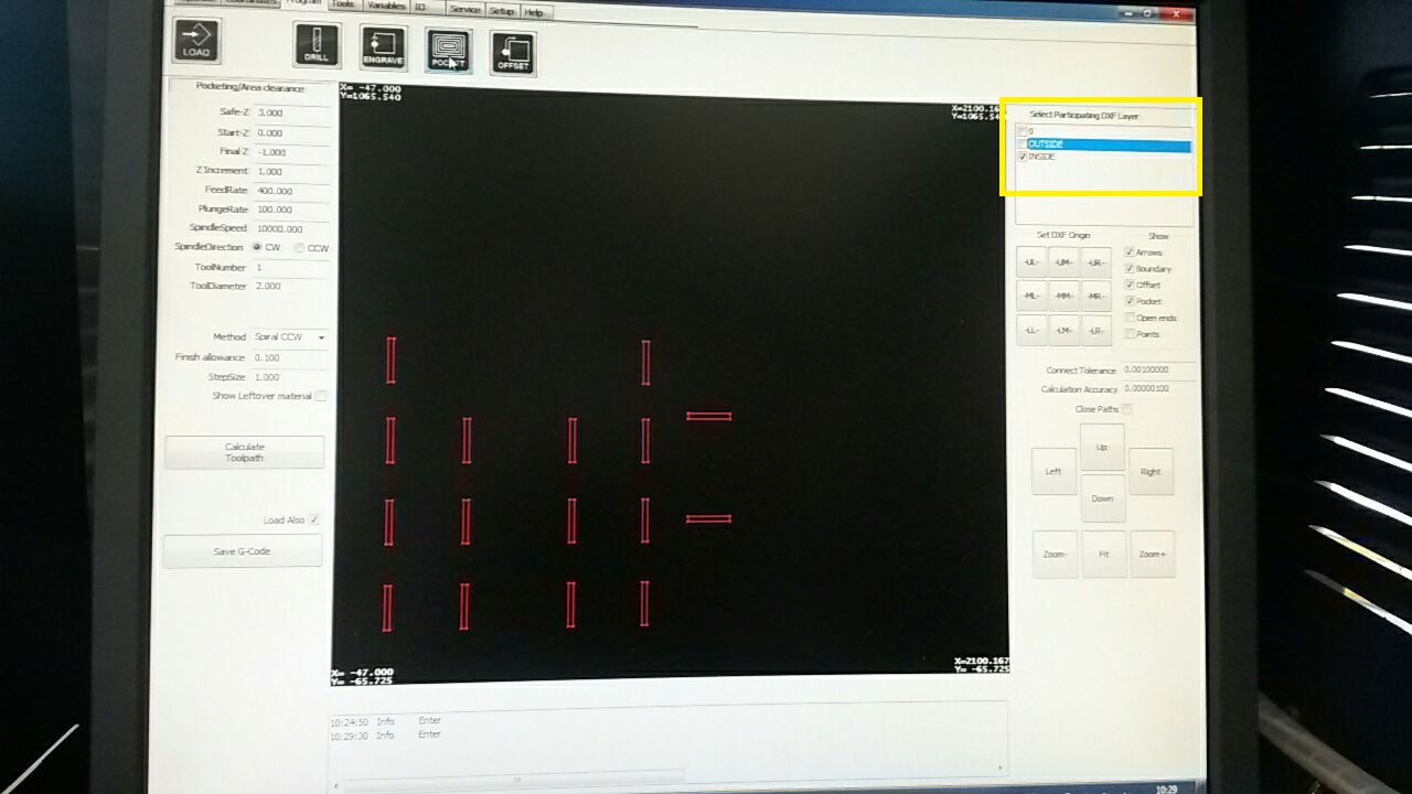
After homing the axes, I inserted my design and pressed LL for Lower Left on the software in order to align the design. After, I hid the outside layer by deselecting it and inserted the parameters. I calculated the path and sent the job by pressing save .gcode after of course I enabled the vaccuum on the bed. After enabling the vaccuum on the bed we press it again with our hands just to be sure. In my case the vaccuum did not work on the bottom part so I had to place nails with the help of my instructor.
Before launching the cut, the layers should be separated and be launched as different jobs after setting the appropriate parameters. The toolnumber chosen was the 1st one which is a 4mm diameter tool with a flat end.
The settings used for the inside and outside cut are displayed in the table below. Feed rate is the speed in which the tool is moving, or "fed" over the work piece. The plunge rate is used to control the pluge moves into the material during transfer motions when the tool picks up from one area and moves to another before starting to cut but it is not used to control the speed of z-moves. Spindle speed is the rate of rotation of the spindle where the tool is held and it is measured in revolutions per minute (RPMs).
| Inside Parameters | Outside Parameters | |
|---|---|---|
| 2000 | Feed Rate | 400 |
| 800 | Plunge Rate | 100 |
| 18000 | Spindle Rate | 10000 |
Assembly
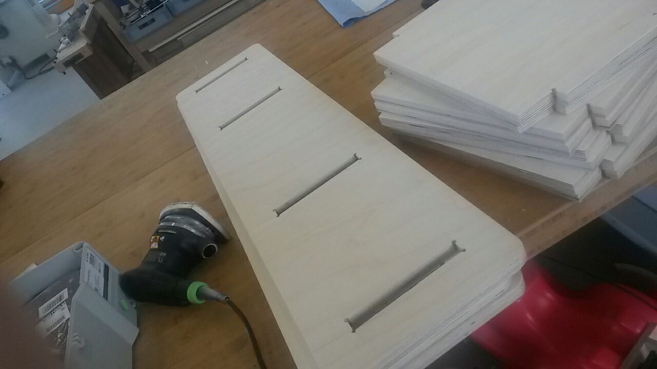
So, after the end of the machining, I disabled the vaccuum, took out the pieces, and vaccuumed again the bed for the debris made from the cut of my design. After, I took all the pieces and smoothed them with sandpaper. Lastly, I assembled them and sandpapered once again the edges of my bookcase.
Download