Week13 : networking and communications
The first thought I had for the networking assignment was to have the two circuits I did for the input and ouput week to communicated between each other. I sketched the concept and tried to work on each part in it's respective assignment.
When the time arrived to test two circuits as my master and slaved I used the input circuit where light resistor is sensing change in light and then the slave would response by blinking the led when the light intensity is less than a certain pre defined threshold.
I2C protocol
I chose to use the I2C bus as a communication protocol between two of my previous circuits. I tried to look into using I2C for attiny. In the attiny DataSheet there is no mention of I2C, instead there is the Two-wire Mode which as mentioned in the DataSheet
The USI two-wire mode is compliant to the Inter IC (TWI) bus protocol
Then the following figure on the data sheet illustrates the connections in the two wire mode. So in essence the Attiny has the Universal Serial Interface (USI) that can be used for I2C.
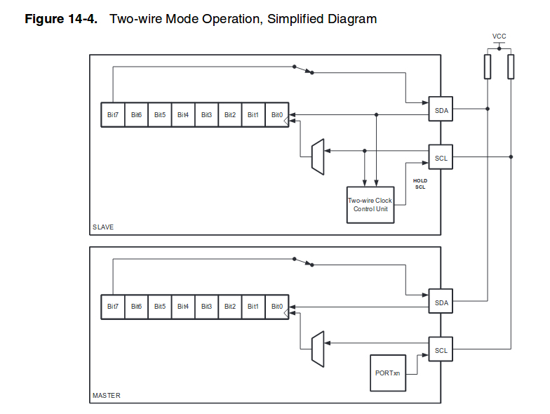
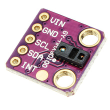
And by reading further I was convenced it is similar, specialy when the pin names used in this mode are SCL and SDA. Those are also used when connecting some sensors to a microcontroller, as for example the MAX30100 pulse oximeter which I am using on a project.
When searching for I2C and the attiny I found the Tiny Wire Library by BroHogan, who based his USITWIMaster on a code by jkl and his Slave code on code by Don Blake . He explained on the arduino playground page the basic usage example for Master node as follows :
USAGE is modeled after the standard Wire library . . .
 Put in setup():
       TinyWireM.begin(){                               // initialize I2C lib
 To Send:
       TinyWireM.beginTransmission(uint8_t slaveAddr){  // setup slave's address (7 bit address - same as Wire)
       TinyWireM.send(uint8_t data){                    // buffer up bytes to send - can be called multiple times
       someByte = TinyWireM.endTransmission(){          // actually send the bytes in the buffer
	                                                // returns (optional) 0 = sucess or see USI_TWI_Master.h for error codes
 To Receive:
       someByte = TinyWireM.requestFrom(uint8_t slaveAddr, uint8_t numBytes){      // reads 'numBytes' from slave's address
	                                                // (usage optional) returns 0= success or see USI_TWI_Master.h for error codes
       someByte = TinyWireM.receive(){                  // returns the next byte in the received buffer - called multiple times
       someByte = TinyWireM.available(){                // returns the number of unread bytes in the received buffer
And the one for the Slave node
USAGE is modeled after the standard Wire library . . .
 Put in setup():
       TinyWireS.begin(I2C_SLAVE_ADDR);              // initialize I2C lib & setup slave's address (7 bit - same as Wire)

 To Receive:
   someByte = TinyWireS.available(){                // returns the number of bytes in the received buffer
   someByte = TinyWireS.receive(){                  // returns the next byte in the received buffer

 To Send:
       TinyWireS.send(uint8_t data){                // sends a requested byte to master
For my Master Circuit I used my input circuit which is reading the value of the photo resistor. And based on the values a simple message is sent to the slave which I used my LED-Button circuit for that.
The master circuit was used in the input week, the values from the LDR are read and via a virtual serial connection using the Tx Rx pins in the FTDI connection I print the values on the serial monitor window. I used a software serial library to do that.Once a threshold is reached a message is sent to the slave. On my slave side and once a message is sent from the master an LED lights up.
My code was simply checking if the value of the Photo resistor is more than 100 a message of byte value 1 is sent. Through the I2C bus to the slave at address 4.
#include <TinyWireS.h>

const int ledPin = 8;
byte value = 0;

void setup() {
 TinyWireS.begin(8);
 pinMode(ledPin, OUTPUT);

}


void loop(){
  digitalWrite(ledPin,HIGH);
  while(TinyWireS.available()){
  value = TinyWireS.receive();

 if (value == 1){

   digitalWrite(ledPin, HIGH);
  } else {

    //if value of message is not == 1
    // turn LED off:

   digitalWrite(ledPin, LOW);
  }

 }
}
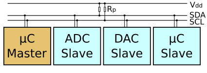
I found out from reading about the I2C that pullup resistors are required. I tried a resistor of value 5k ohm and nothing happened then when I used another larg er value like 10k. Then everything worked. Also when using tinywire library we can't use delay or it will breake the connection.
The values were also visable on the serial monitor to validate that the condition to send the message is working correctly.