Week11 : Output Device
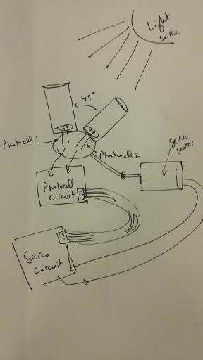
This is a follow on the idea I started in the input week. Where I have a servo motor move accoring to the light direction.
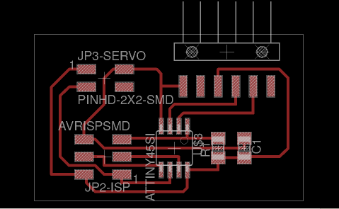
I started by designing the servo circuit in Eagle.
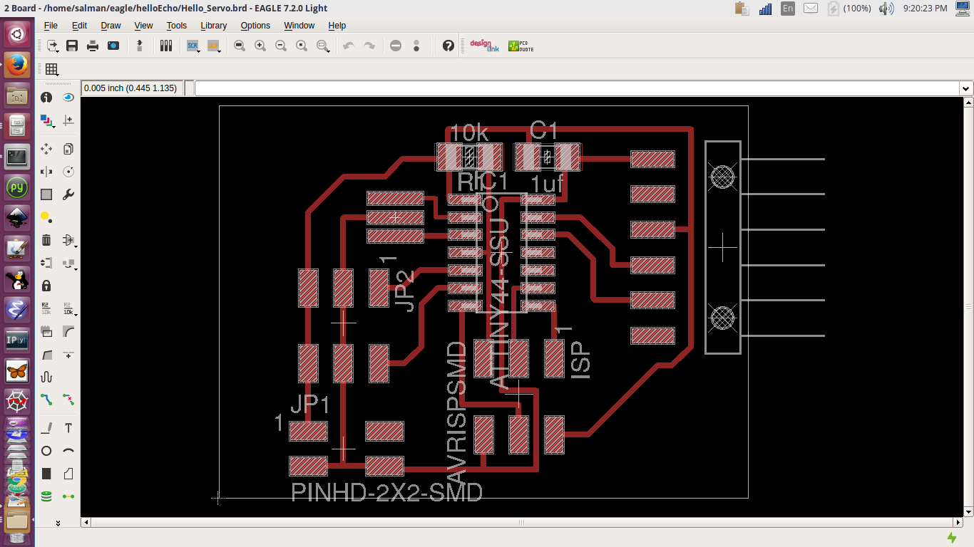
tiny44-servo board tiny44-servo schematic
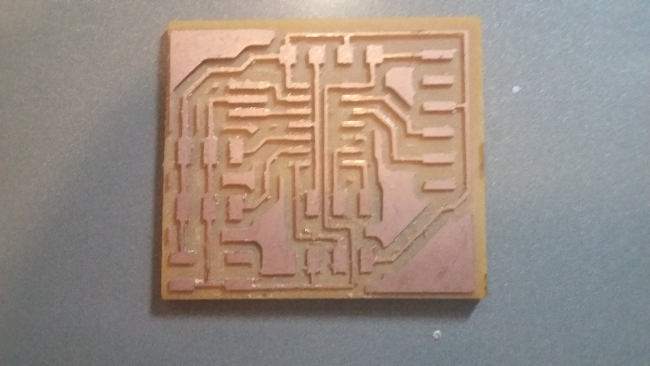
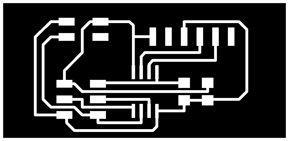
And I milled the PCB.
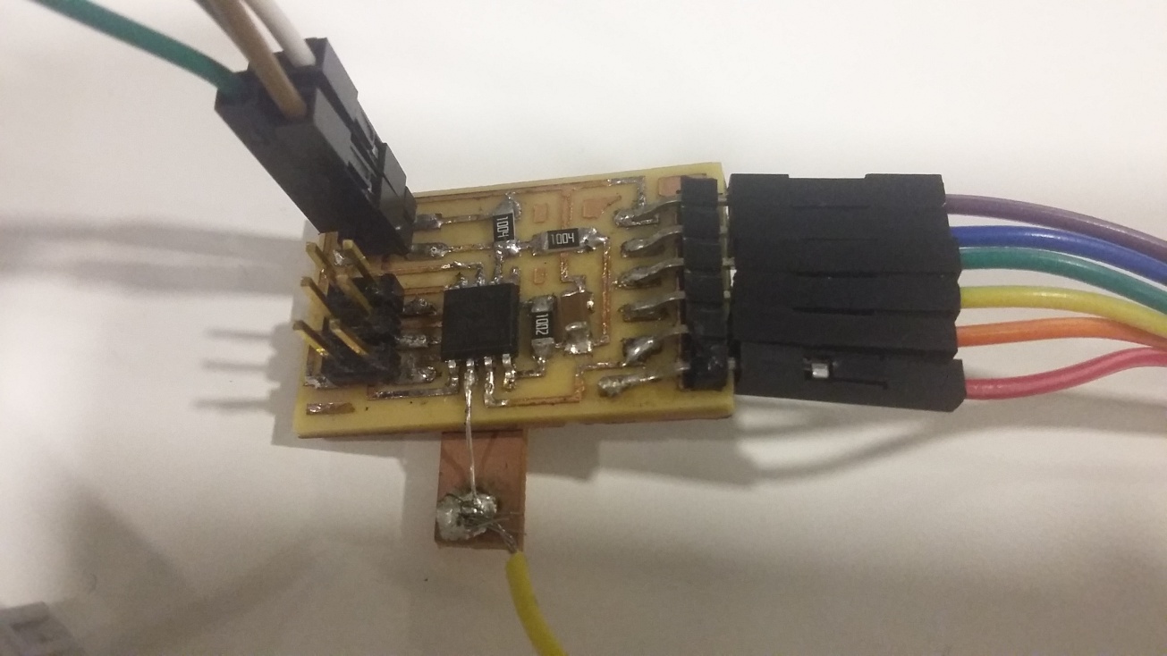
I used an Attiny45 circuit that I had ready for testing the code and identified the pin for PWM from the pinout diagram.
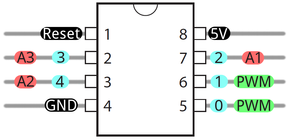
Which I easliy soldered a wire to and used it as my PWM pin, and had to draw the voltage and connect the ground to the pins in the ISP connection.
There are different servos around and each maker has a different color code for the wires that identify the ground, signal and vcc. The following diagram will help
I wrote a simple code that moves the servo between 0 and 180 degrees incrementaly one step at a time, then the servo will turn back to 0 from 180.
I later designed a new circuit based on the attiny45 I used.