Week10 : Input Devices
LDR photo sensor
Intially prior to the lecture I had in mind an idea to creat using multiple photo cells and object that would follow the light source, in this case I had the sun light source. I thought a mechanisim like the sunflower.

This mechanisim as i thought could be used in less privilaged countries (less sun light) for moving solar panels to get the most of the sunlight during the day. And in much prevelaged countries(extremly bright through out the year) could help creat smart shades for people working in the outdoors.
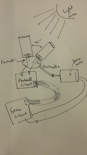
So I had it planned ahead, I should use three assignments to complete the whole concept. I would start with a circuit for the two photo cells as an input signal. The difference in voltage/resistance between the two photo cells would indicate the direction of the servo rotation. So if for example if 'Photocell1' had higher voltage( indicator of low resistance as a result of more incident light) than 'Photocell2' the whole holder will move towards the more light untill the difference is below a certain tollerable threshhold.
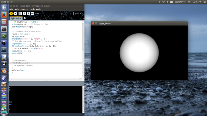
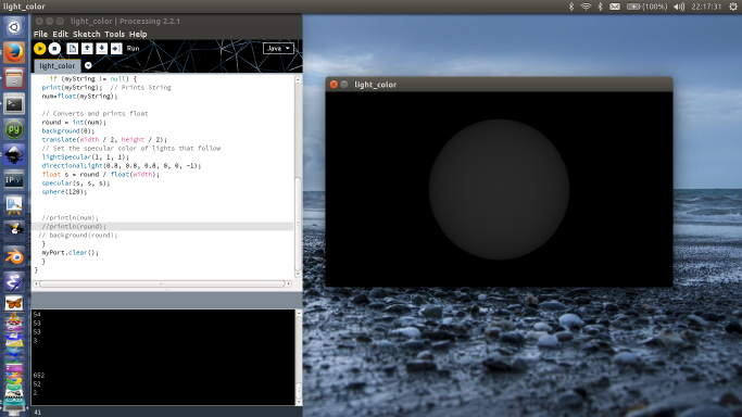
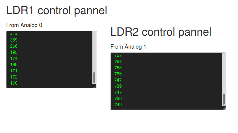
I did several tests for an interface that would visualize in real time the change in the light intensity at each cell. I used processing to create two different simple visulaizations and also Firmata on Arduino with Node.js Socket.io and Jhonny Five to see the changes in voltage in the range from 0-1023 on a browser.


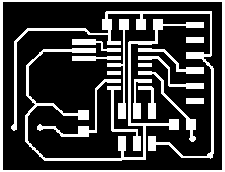
For the circuit I tried to start with one of the existing circuits i have done. That was the one with 2 LEDs and a Button, I changed the connection and the tracing to make it look a bit interesting and compact.
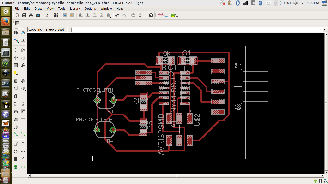
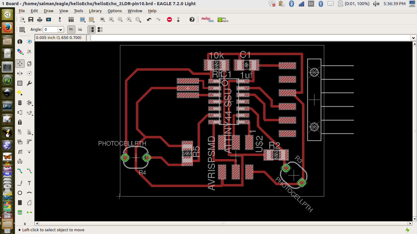
Then after going through the attiny44 data sheet i realised that I am using a digital pin where I should use an analog pin. So I did a final tweek in the design where the second phot cell was connected to pin 10.
The first milling was not succussful, I realized that my drill bit was broken and not in a good way. That resulted in a extremlly thin traces.
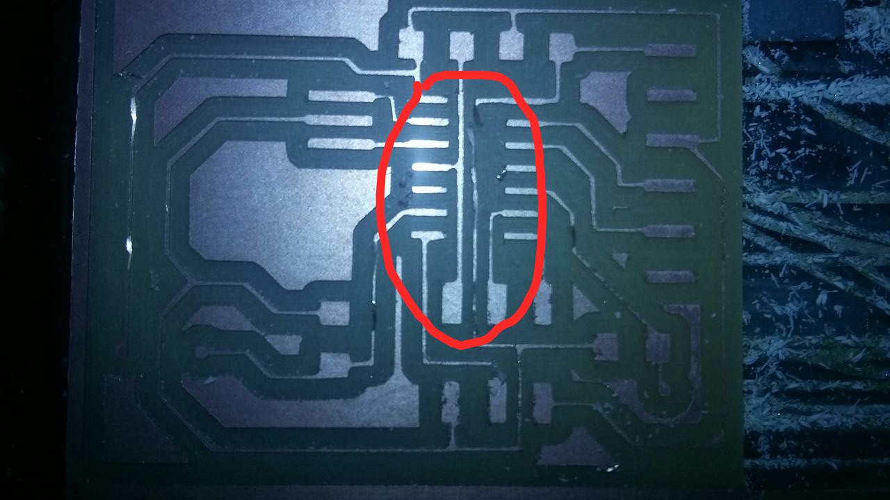
I had to reduce the offset to 3 and milled again. It was succufful this time, though the traces where still thin. I stuffed the circuit and tested using an Arduino IDE.
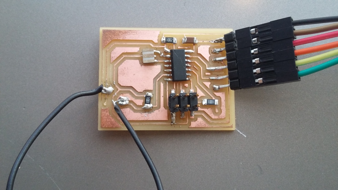
In this setup I used both an LDR and an LED, if the value of the LDR reaches a certain low value the LED turn on.
Tx Rx
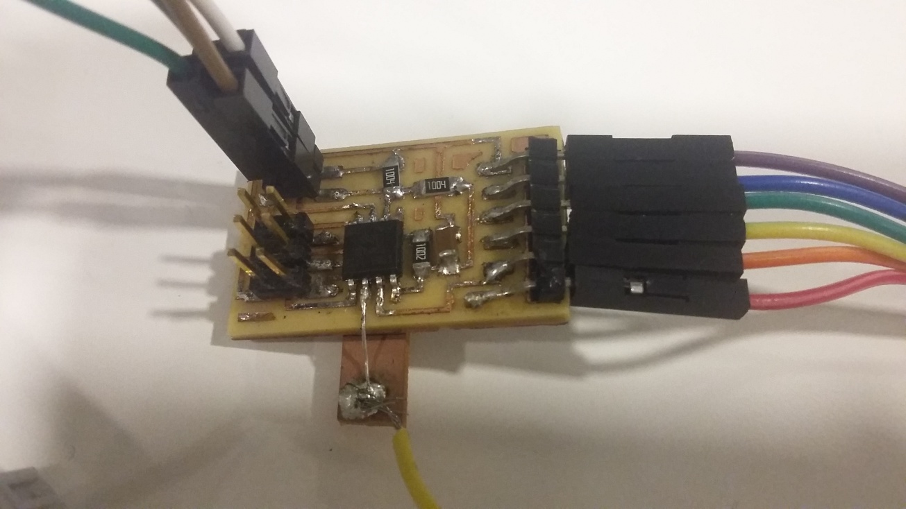
I tried other circuits in this week, I tried the attiny45 TxRx circuit.
The milling and stuffing of the circuit was fast, and debuging didn't reveal any issues. When connecting the circuit to the ISP programmer and powering it I was able to get a response without errors to the following
avrdude -c usbtiny -p t45 -P usb
Then programming using avr-dude was smooth, I used a make file and
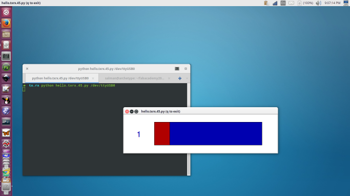
But when I ran the pyhton code, I had the indicator fixed at one. No change, I tried checking the serial monitor on an Arduino but I the output was not so helpful. I assumed that it has to do with the fuses?! As I have faced the same issue with other circuits.
I tried later to burn a bootloader as I did for other circuits, and the circuit was working. I tested analog input and pwm on pin 1 and digital output on pins 3 and 4.