Making something in large size
Modeling
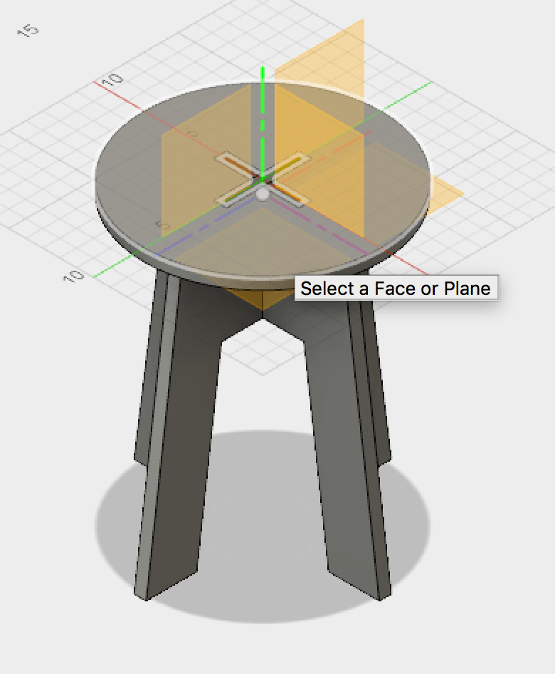
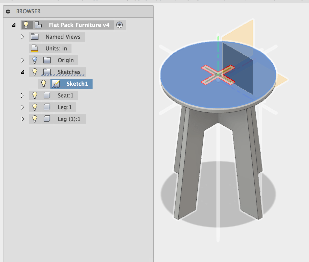
I decided to try out chair which I drew earlier in 3D modeling phase (week2) using Fusion360.
Again, I got this design in tutorial from youtube.(Here you can find link to the tutorial).

Exporting 3d model as 2d plan(.dxf file)
After 3d model is drawn, I got 2d plan for each file according to following step.
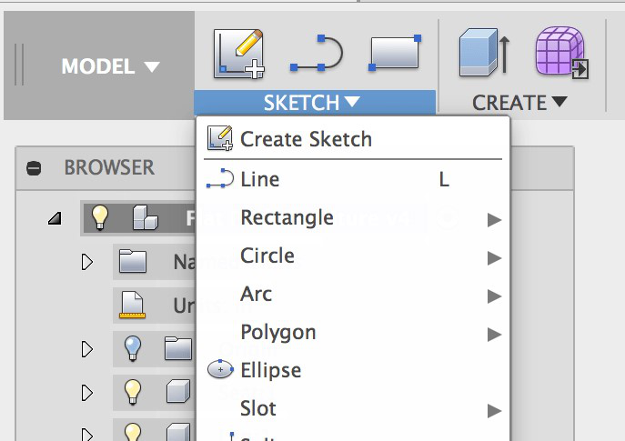
- Sketch> Create Sketch (make sure you are starting from entire model not components.)
- Select Body(Parts)
- Click 'Stop Sketch'
- Right Click> Save it as .DXF file.


Machining: From getting right files to letiting machine moving
CNC machine that we are going to use for this assignment is stepcraft840 machine along with winNC
software(As far as I know, you can only install it in Window based computer).
somehow .dxf extensions might not work well with winNC. I tried exporting files with other extension
such as .plt but it did not also open.
I kept facing this issue, saying data cannot be imported.
While googling the same error, I got to know that .hpgl file extension can also be accepted. so I
changed my .dxf extensions file with .hpgl in Inkscape.
(You can find how to deal with such error in here).
(In this step, you need to change objects to paths(it is under the 'path' menu in Inkscape menu
bar.), and than change it to specified extensions.
You might also need to download 'Uniconverter'
extension modules to Inkscape. Here are details on it.
And after all this, I could finally open my files ready for cutting. yay!
After open the file in WinNC, there are some tedious things to do- yes, it is also very important at
the same time.
- Place two plates into machine(the one in the very below will be the sacrificing plate to save machine from the drills in case.)
- You first set the xy-coordinates with z(height) 1/2 of the possible depth.
- Check the boundary of your design to see if they might go beyond the cutting plate.
- If the boundary is inside than go to zero xy-position and adjust z position until you hear the sound drill touching the plate.
- If you set the xyz-position again then it will remember the right position. Now you are ready to start.
- Set or check he depth of the drill(under 'parameter' and than 'measures') to that it could cut/engrave your material.
- Turn on the drill, and hit 'start' button from the software(button is under 'Move' menu).
Final Touch: Filing or adjusting the slits and assembling XD
After milling is finished, you can turn off the machine and vacuumed the dust.
As edges of the milled parts would still not be fine with lints so we need to sand & file it.
(Marcel told me to sand it window open and demonstrated it to me.)


Difficulties: Adjusting your design according to your milling machine.
Previously, when we were playing with lasercuter, we examined with
the kerf and had to take this into consideration with the design.
Apparently, it seems that we need to care about drill size! Since we had 3mm wood plate which is
small than smallest 6mm drill that we have,
I was surprised that 2 line that I have drawn in design now has added 5~6mm of space wider than the
space what it supposed to be.
Also, due to this restrictions, I had to think about following issues.
- Joints cannot be smaller than 6mm(since trajectories of drills will cut off from either sides and there will be nothing left. - should be larger than drill size + some width where materials can withhold strong.
- When making slits, and pats which go inside the slits. I need to think from two sides - silts will be larger, and parts going in will be smaller than drill size.
- Apart from drill size, it seem there are some parameters lying in softwares that I used(for examples, Inkscape is adding line attached to an object), or some mysteries parameters so I would say it is just better to play around with slit and bricks with materials before start designing. (It is not so exciting work but will relieve time and materials at the end).
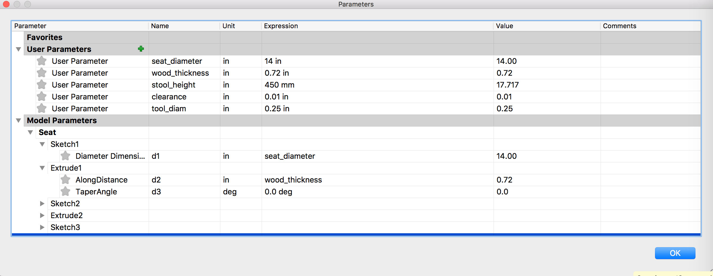
- In adjusting designs with such parameters, parametric design approach that I took with the tutorial seems quite successful.
Troubleshooting
Once we had situation where machine is not working right to x-axis as you can see in the photo
below. Later, we found near to the machine that really smart part which connect stepper motor to the
rod is taken apart.
Putting that tiny part back to where it is, we could be able to cut the shape as we want. Could be a
real frustration if we had not have 'building documentation' near to our hands.
