Electronics Production: PCB Fabrication Process
Preparing files for milling: Create Gerber Files from board and schematic
Everything that I did for this assignment was really new to me. I got to know about this software Eagle
and provided with board and schematic files. I opened up the 'FabUSB' files and


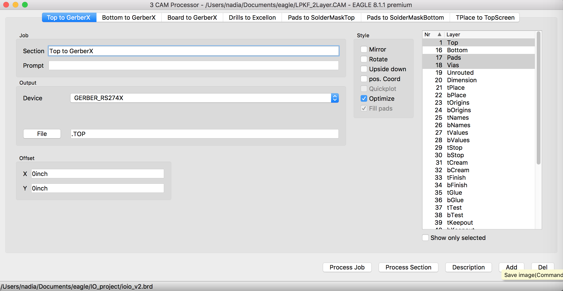
- Open CamProcessor under 'File' menu.
- Open Cam files from 'Open' > 'Job'
- Select 'LPKF_2Layer.CAM' file.
- Change Device into 'GERBER_RS274X'
- In Drills to Excellon Tap, change Device into Excellon24 and Check whether the right .DRD file is included.
- Hit 'Process Job' button
- If you see '.TOP',',BOT','.DRD','.BOA' and several other files, you can consider that this step is successfully carried.


PCB milling machine.
We are using 'LPKF
Protomat S62 PCB mill' in our lab.
Here you can find detailed guideline
for using machine.
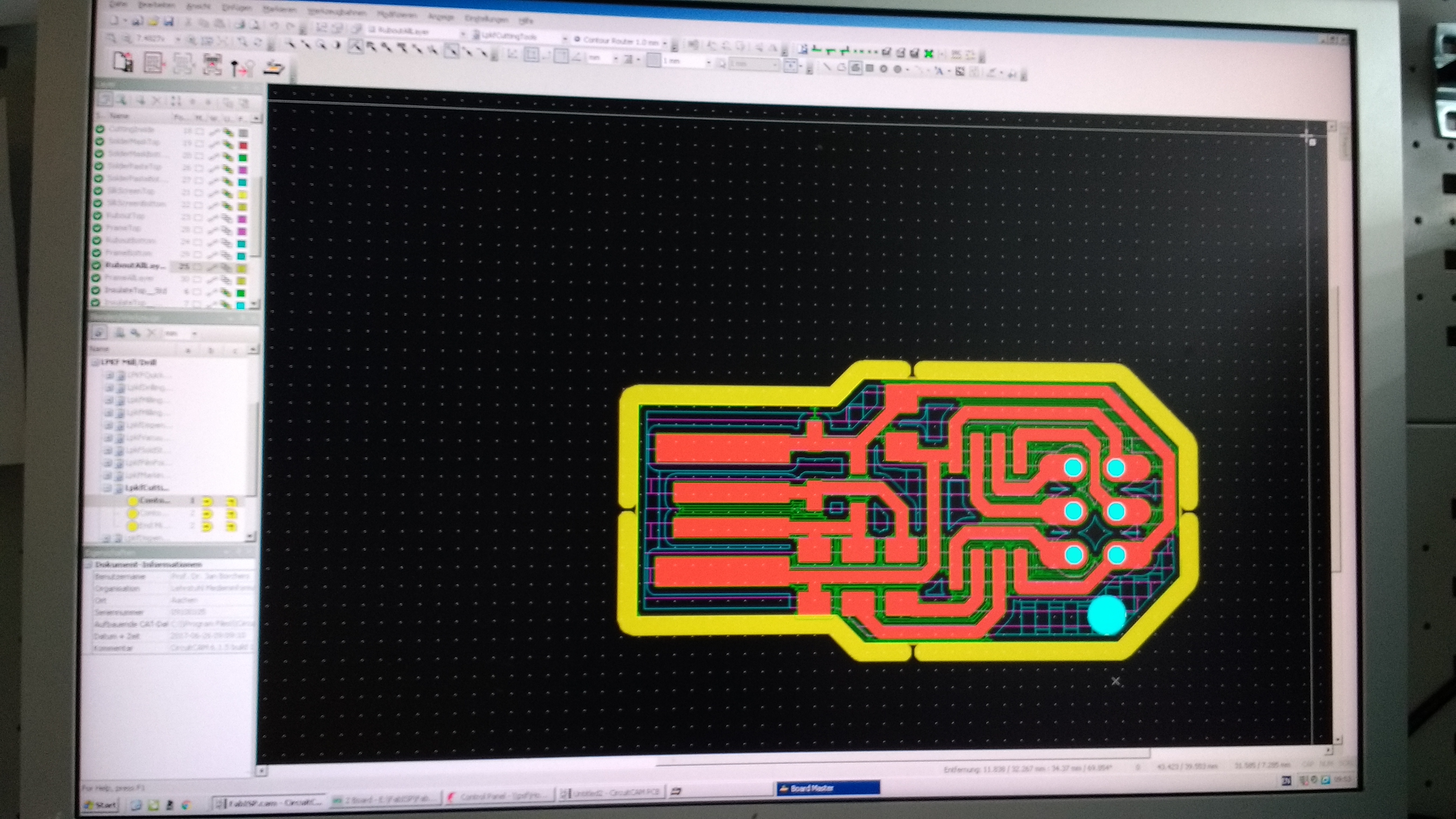
In milling station, you need to create .job files(called 'preprocessing', step5 in linked guideline)
using 'CircuitCCAM' which will actually tell your 'BoardMaster' program and 'PCB mill' what to do.
- Create .job files from CircuitCAM program
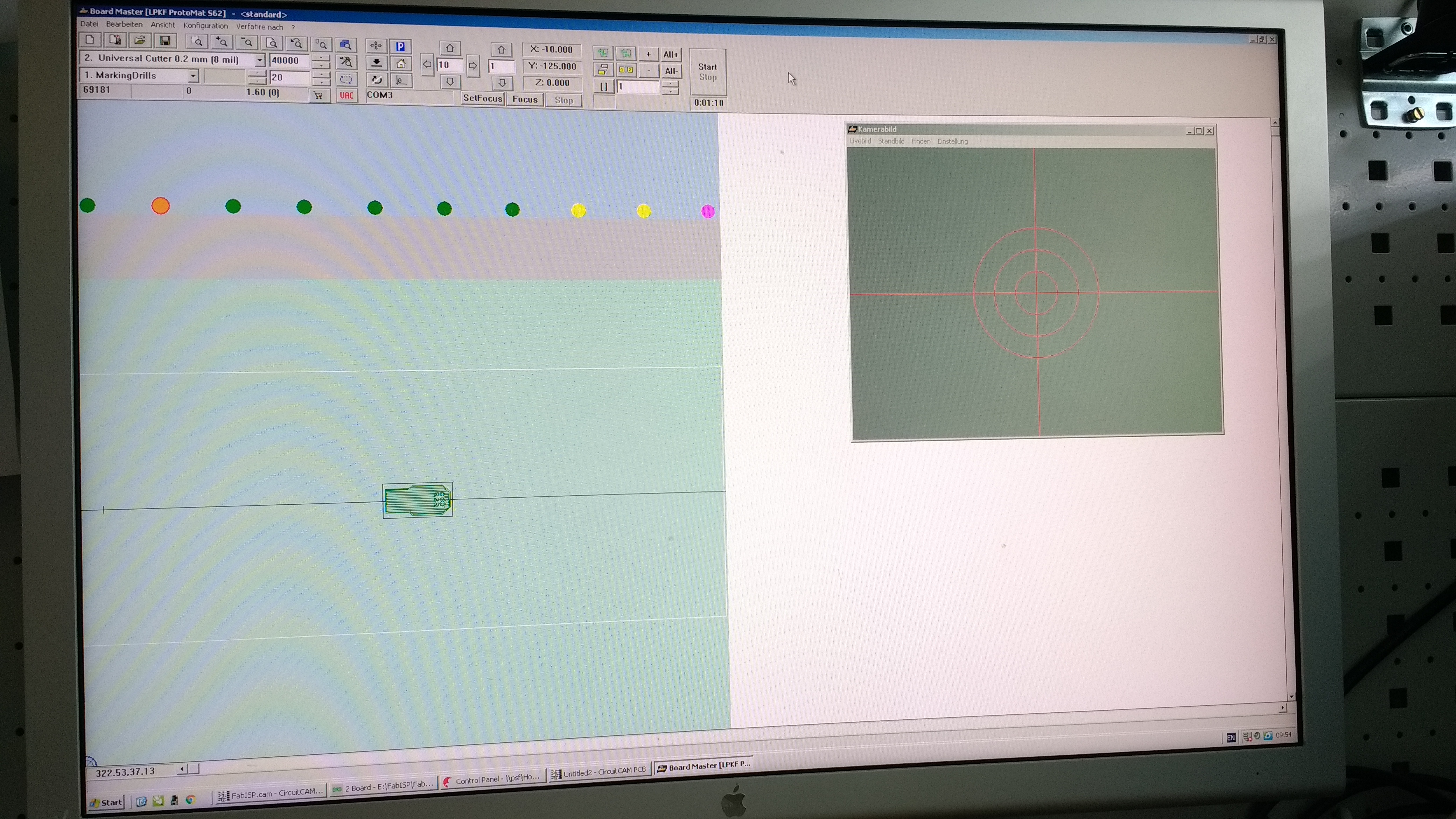
- Set origin for cutting
- Operate milling machine
- Make drills
- Draw circuit & Scrap other parts out
- Cut the outline
- separate you board from the plate, and trim the edge and circuit surface with sand paper.
One tricky thing left is to set the position where to start cutting. We need to do it so as to mill the right parts from the metal sheet, as board is normally small, and we can mill several board with one large metal sheet which normally fits into the size of the machine. so setting zero point economically is somewhat important. After this step is done. there are just 3 buttons left until you get board ready to be soldered.
- How milling machine is working (so it just needed 3 buttons from the 'BoardMaster' software)

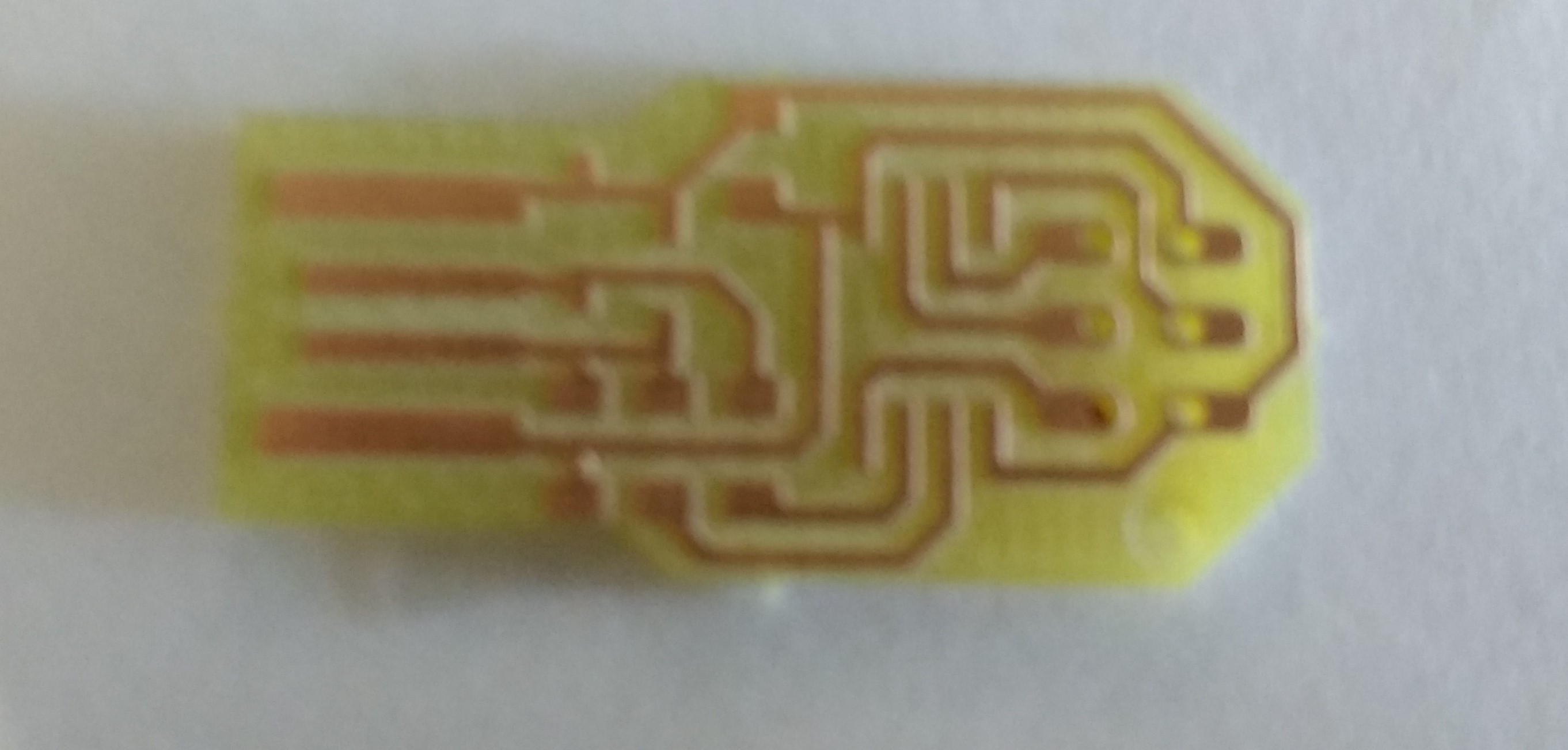
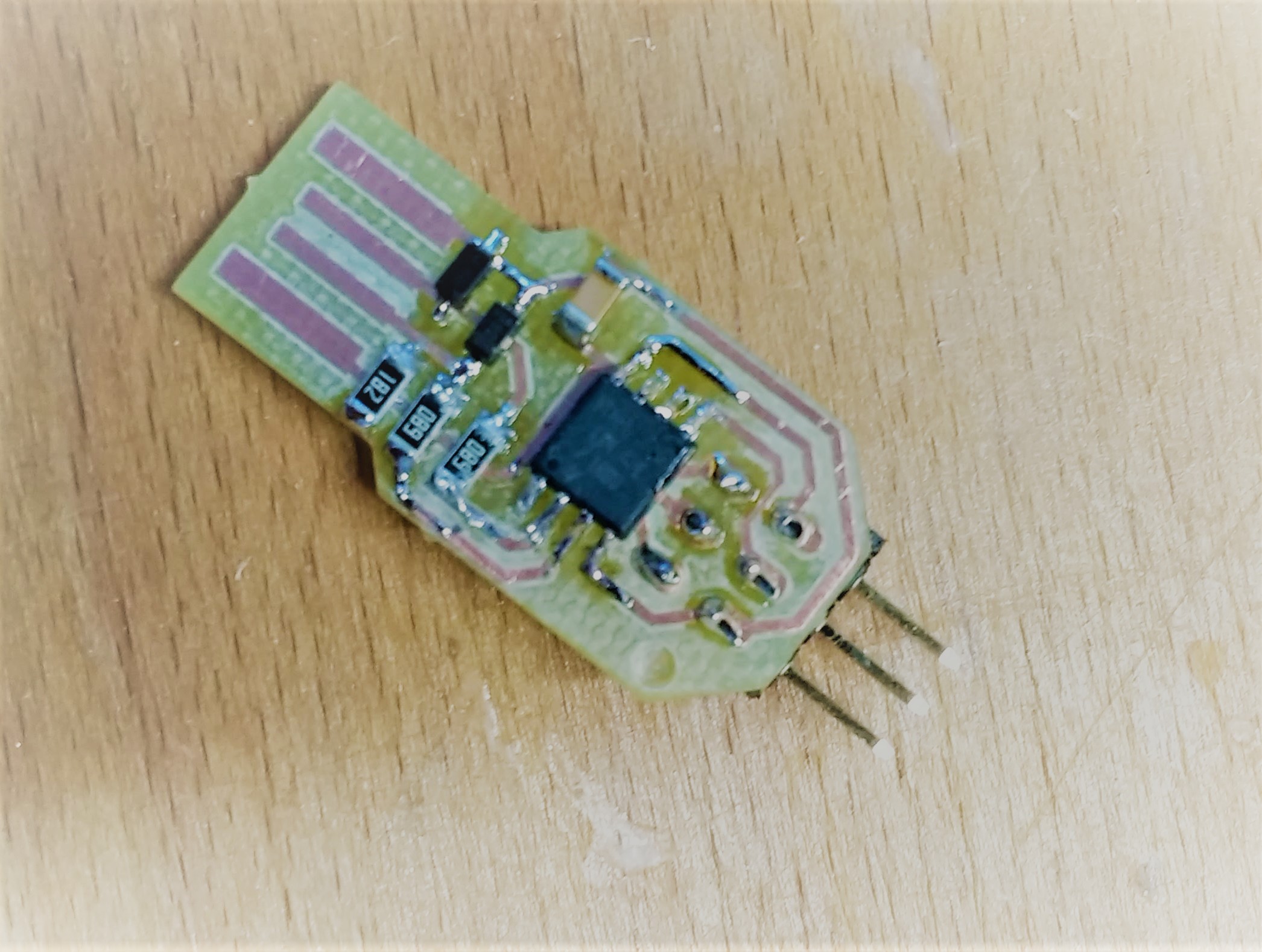
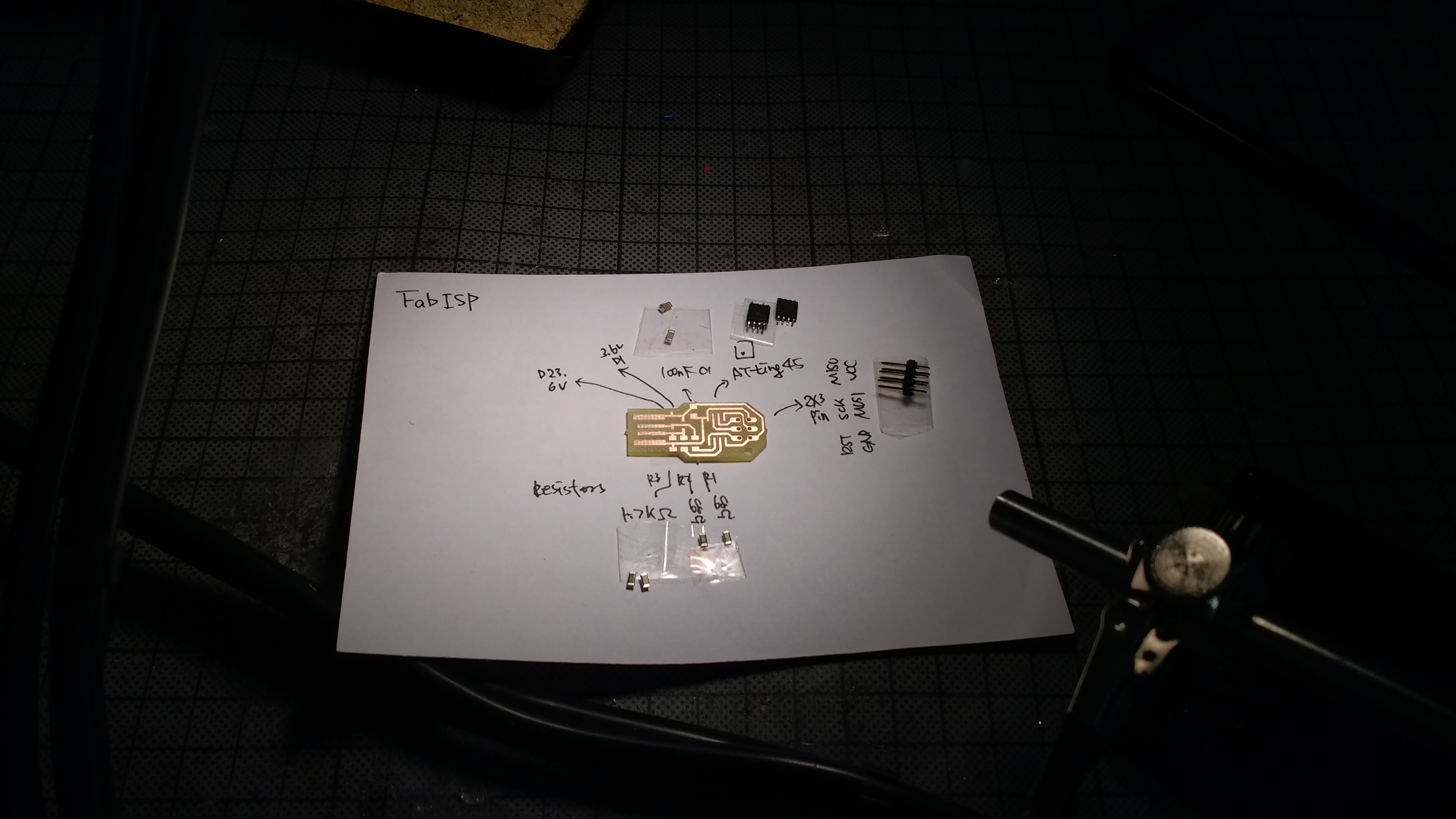
Now we are ready to solder (or stuff)!
Collecting components for soldering
These is a list of components making FabISP.
- Microcontroller Attiny 45
- 2x3 Pinheader 2,54mm
- 2 x Diode 3,3V SOD-123
- 2 x 680 Ω Resistor
- 1 x 1.8 kΩ Resistor
- 1 x 100 nF capacitor 1206
Tips for easy soldering
We actually tried making circuit by stuffing with silver paste at first. As pasting method of making a PCB didn't really work successfully, we later had to develop our skills on soldering, which I have feared of so long. And finally in a week of 13 thanks to 'Lukas' from our lab, who gave me Soldering101 Lesson, Milling and Soldering ent Easy! To share what I shared, here I wrote down tips. (can be redundant with Week13).
- Heat the PCB and connecting parts first, before heating and trying to melt the Lead hastily. When PCB parts get heated enough, later melted lead will just surround the connecting parts.
- You don't need to use lot of Lead, so maybe you can melt a little bit of lead first in your soldering iron, and try to connect PCB and chips.
- Start with one part of SMD(small parts), it is hold well, then next step is way easy.
- When soldering chip, you can also start with soldering one bottom leg and then the one up, across to it, to hold the rest of the parts.
- When soldering Pinheader, you can attach it from bottom. Here you can heat to PCB and connecting parts first, and apply lead wire on the other side of the heat. Then you can get nice corn shape;)
- Keep your soldering iron clean, otherwise it does not pass the heat properly.
- In case of excessive drop felt into the connecting parts. Using small amount of gel, copper wire to soak the lead, syringe to pump(?) it up again might help.
Testing
After soldering, we programmed the board.
To Program the board, we first set the Arduino as an AVR ISP(In-System Programmer). For this step, we
followed the steps written here.
And we also downloaded the software to program fabISP.
We followed the way described in Anna
Kaziunas Frances's tutorial
till this point. When we were actually trying to program Attiny45 with the way it was written in her
tutorial, it didn't work.
And then We found 'Building the
FabTinyISP' tutorial
very helpful in programming Attiny45.
Then we edited the code that Anna was provided and by changing the programmer, and added the USB
variable to the make file.
After this step, we connected the Arduino with FabISP and run the following commands:
- make
- make flash
- make fuses
- make rstdisbl
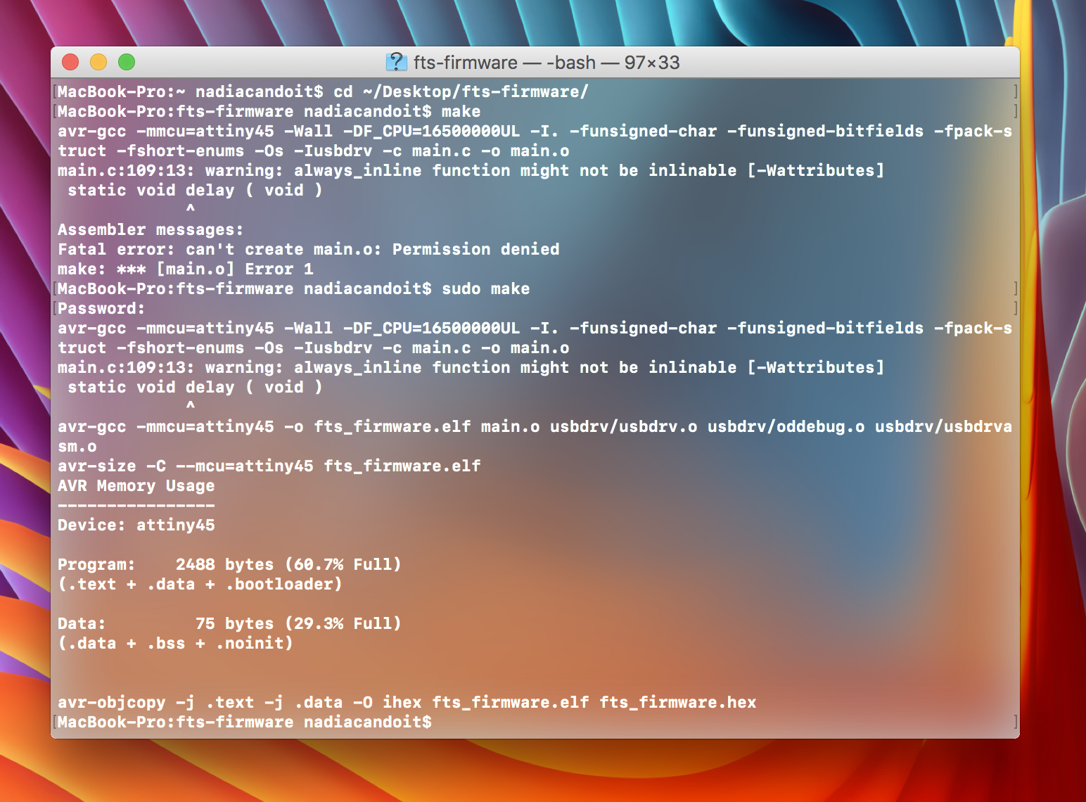
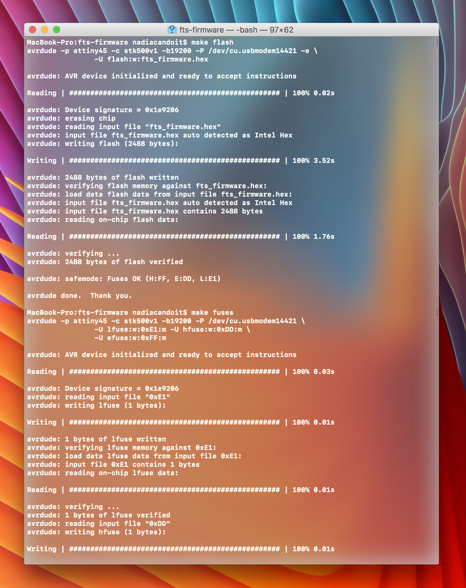
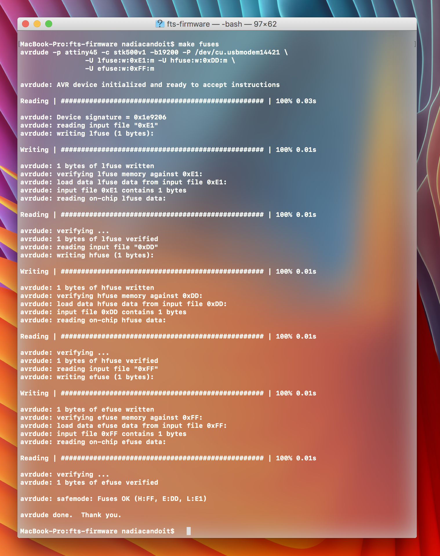
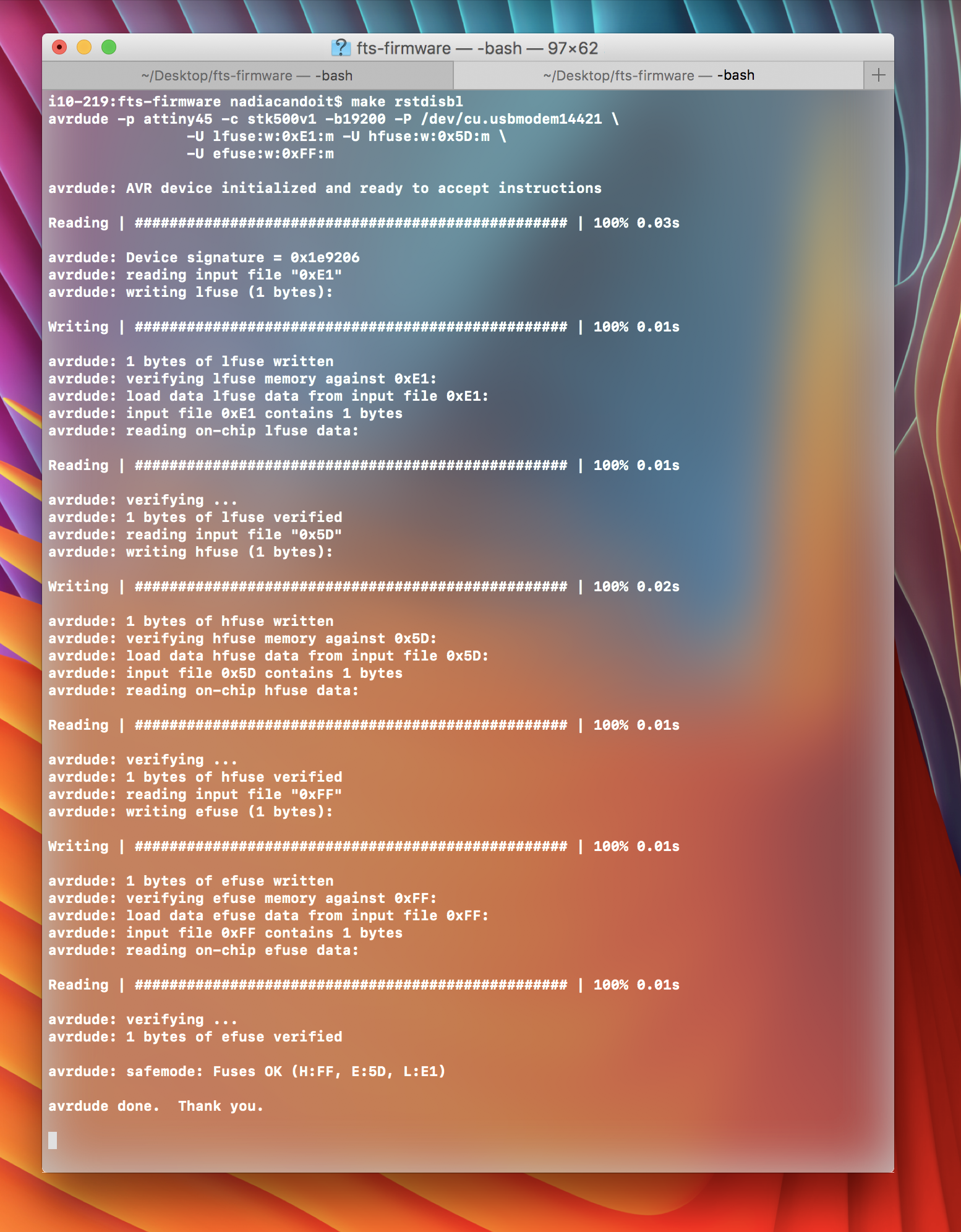
Below is result from the assignment.