More PCB Making and Let Servo motor moves with Attiny44
As previous weeks of designing and making a PCB took me a lot of time to acquire a mastery to a certain level, I happened to and had to carry all the electronics assignments at the same time. Therefore there might be a time gap between each week's assignment, such as in this case. I finalized with this week's assignment(week10) after week13(Input device).
Lesson learned from circuit design phase: Servo motor would require analog input! (Update no it does not ;) )
I initially planned out to design a board which can cover output device and input device(week13. photoresistor and led) at the same time.
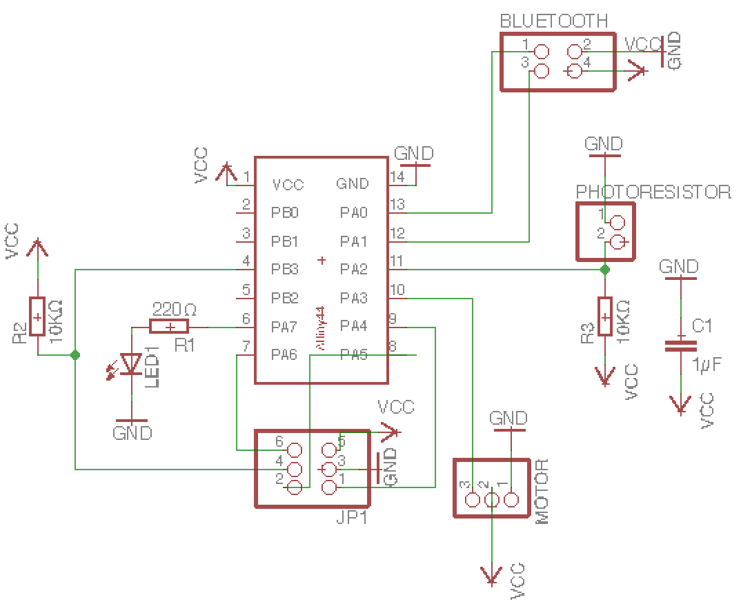
But it was impossible with the previous board from week13(input device), because I connected the pin-header for servo motor to PB than PA.
So this time, I made one board where pinHeader for Servo goes to PA(not PB) and finished soldering.
Later I found, there was a little problem(again!) that signal to pinheader is placed in the middle, which supposed to be placed at the right, next to VCC.
Although it might be okay to use it, if I take some care when connecting to the ATtiny, but I decided to solder a new one, which Paulina has shared with us.
Update: After talking again to my instructor Marcel about the analog and digital pin with PWM I learned that I had a misunderstanding of this. PWM (which attiny and servor motor use for communication) works with a digital signal and thus I can also use a digital pin. But I have to look into datasheet which digital pin is capable of doing PWM. So I learned more about how Pulse Width Modulation works by reading the Wikipedia article for example. It is a communication protocol which structure the communication by Having HIGH and LOW signals with different time length. Both Sides of communication need to use the same structure of PWM. Therefore I need to learn how PWM for Servo works or find a library which has ready signal structure already modelled.
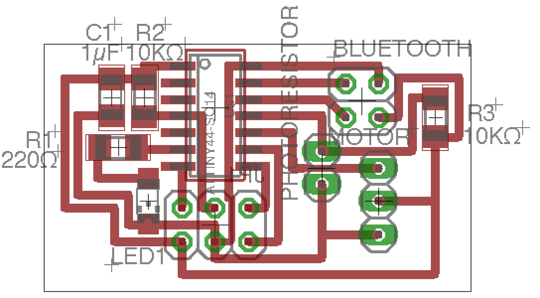
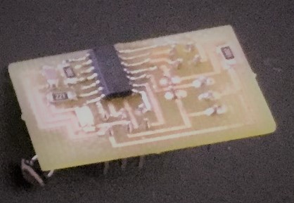
After all, I feel like milling & soldering is now a enjoyable thing to do. Here are images of (the ultimate) schematic, board, soldered PCB.
Understanding Servo Motor: From Programming to Wiring for Upload
ServoMotor
Servo motor turns its arm from 0 to 180 degree (this might depend on model but it cannot do unlimited rotations like a stepper motor).
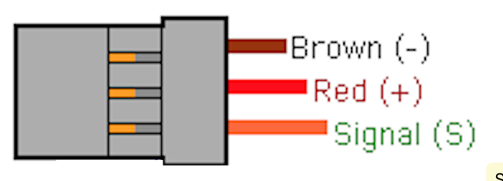
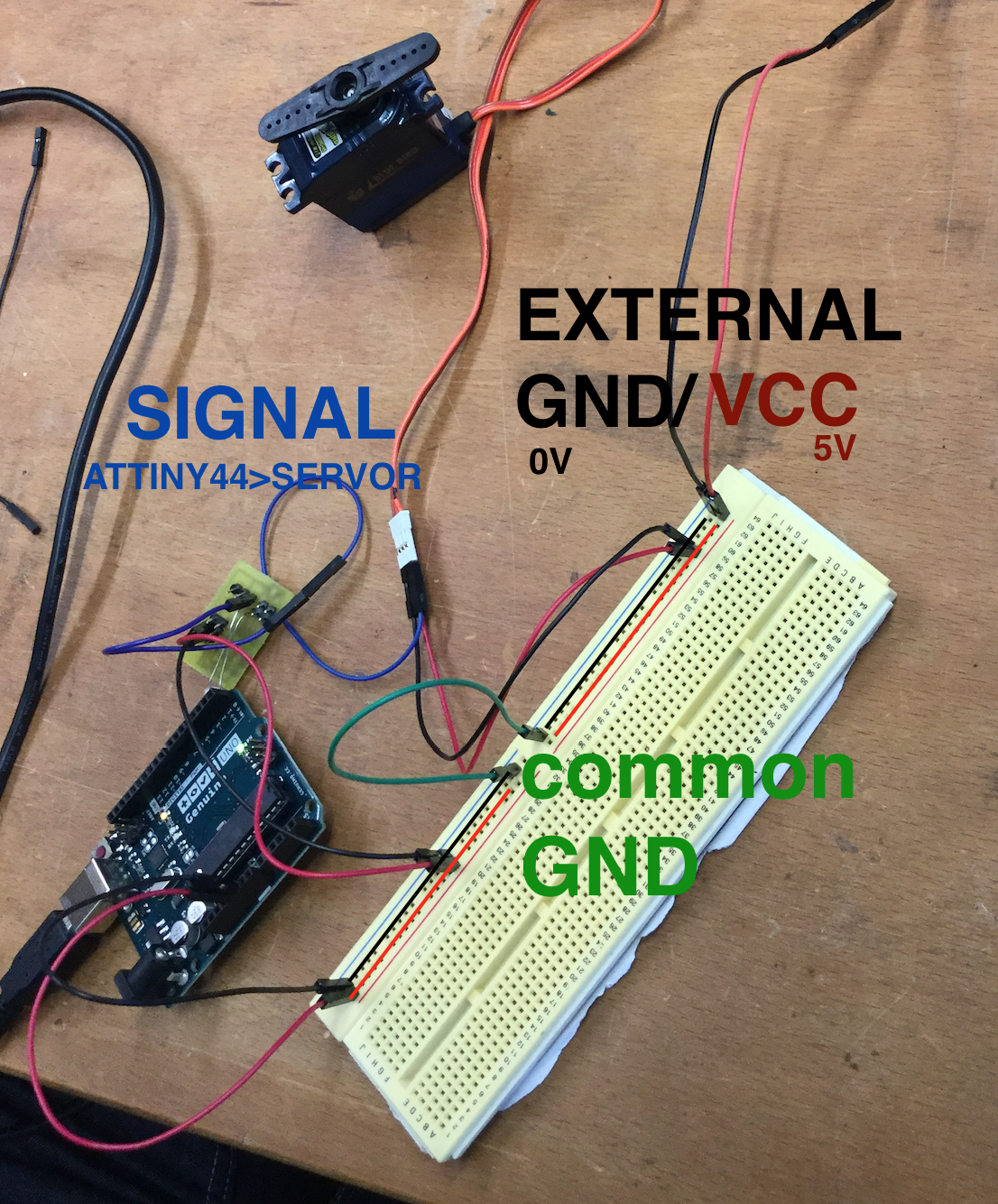
Although it is minor problem wiring matters, It has a female connector with three pin- GND, VCC(5V),
and signal pin which needs to be connected to a digital pin of the Arduino.
As pins in the connector are all connected, you need to bear in mind from designing a PCB pin for a servo motor.
Power to the Servo motor from the Arduino alone is not good enough and we need to provide external source of power.
If external source of power is not given, your servo motor will just end up fizzing & fidgeting than doing what it supposes to do.
In this case, we need to provide a common ground between arduino and PCB and servo motor a common ground.
HOW TO: Program ATtiny44 to move Servo Motor
  #include <SoftwareServo.h> // Library to run a servo motor in software for micro controllers which are lacking servo support

  SoftwareServo myservo; // initialize servo object
  const int LED = 7;   // Pin for a LED
  const int motor = 3;   // Pin for a motor

   // setup function runs once on startup of the microcontroller
   void setup()
   {
     pinMode(LED,OUTPUT);   // initialize digital pin LED as an output
     myservo.attach(motor);  // attach servo object to a motor pin
   }

   // loop function runs over and over again forever
   void loop()
   {
    digitalWrite(LED,HIGH);     // LED On - providing the LED Pin with 5V
    myservo.write(12);          // this turns the servo to the 12 Degree position.
    SoftwareServo::refresh();

    delay(1000);

    digitalWrite(LED,LOW);      // ED Off - pulling the connection to GND (0V)
    myservo.write(54);         // this turns the servo to the 54 Degree position.
    SoftwareServo::refresh();
    delay(1000);
   }
We are using additional header file provided by Arduino Library which is called SoftWareServo. I use this because because it provides the PWM Signal structure such that I do not have to programm the HIGH and LOW signals myself.
First I tried to try with the sample code from Arduino. It did not work smoothly as it did in the previous weeks.
It shows an error regarding 'SoftwareSerial.h', saying that it again needs (but cannot find) another header file called 'WProgram.h'.
I got to know that 'WProgram.h' is used in 'SoftwareServo.h' and ''SoftwareSerial.cpp', and replaced 'WProgram.h' inside those files with 'Arduino.h' and it could compile.
To set up the servo motor you need to create servo object and attach it to the pin where the signal wire of the servo is connected to.
In the loop, you can set the value between 0 and 180 I set it between 12 and 54.
According to the documentation, SoftwareServo::refresh() method needed to called every 50ms (or even in smaller interval), to keep the servo updated.
 void motor_delay(int delayTime)
{
  int delay_Factor = 20;

  for (int i = 0; i <= (int)(delayTime/delay_Factor); i++)
    {
      SoftwareServo::refresh();
      delay(delay_Factor);       // delays the execution of the next line of code by delay_Factor milli seconds
    }
}
Our instructor has provided us with this method which makes it possible to have desired delay time longer than 50m as an input and still call the method SoftwareServo::refresh() every delay_factor ms. Having this, we could substitute delay(1000) on loop with motor_delay(1000) and still have SoftwareServo::refresh() called regularly.
Below is result from the assignment.