Electronics production
Week 4
Preparing the file
Well, this step of the process has been done without any issues. FabModules was really easy to use and very clear to understand. Here's how we did it, I'm saying this we because we did all the process together François Auclair and me.
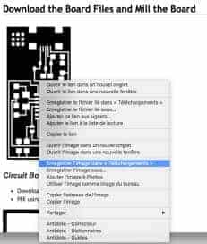
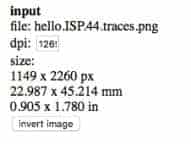
1. Import the traces file
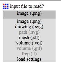
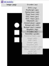
2. Choose the output. In this case, I had to chose G-codes (.nc)
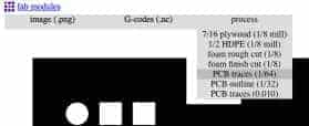
3. Choose the process. For the traces file, we chose the 1/64 (traces) as it was clearly indicated to be chosen.
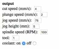
4. Choosing the right settings. We started with the by default settings to test the match with our own CNC milling machine.
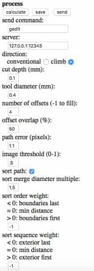
5. Calculate the process so you can have an idea of how the machine will execute de job.
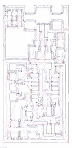
Until then, there was no problem following the process and suggested methods. The problems, will come in the next phases. It's possible to take a look at the Gcode here. Finaly, I did the same process for the outline file. This time I chose in the process the PCB outline (1/32). You can look at the Gcode here.
Milling the PCB
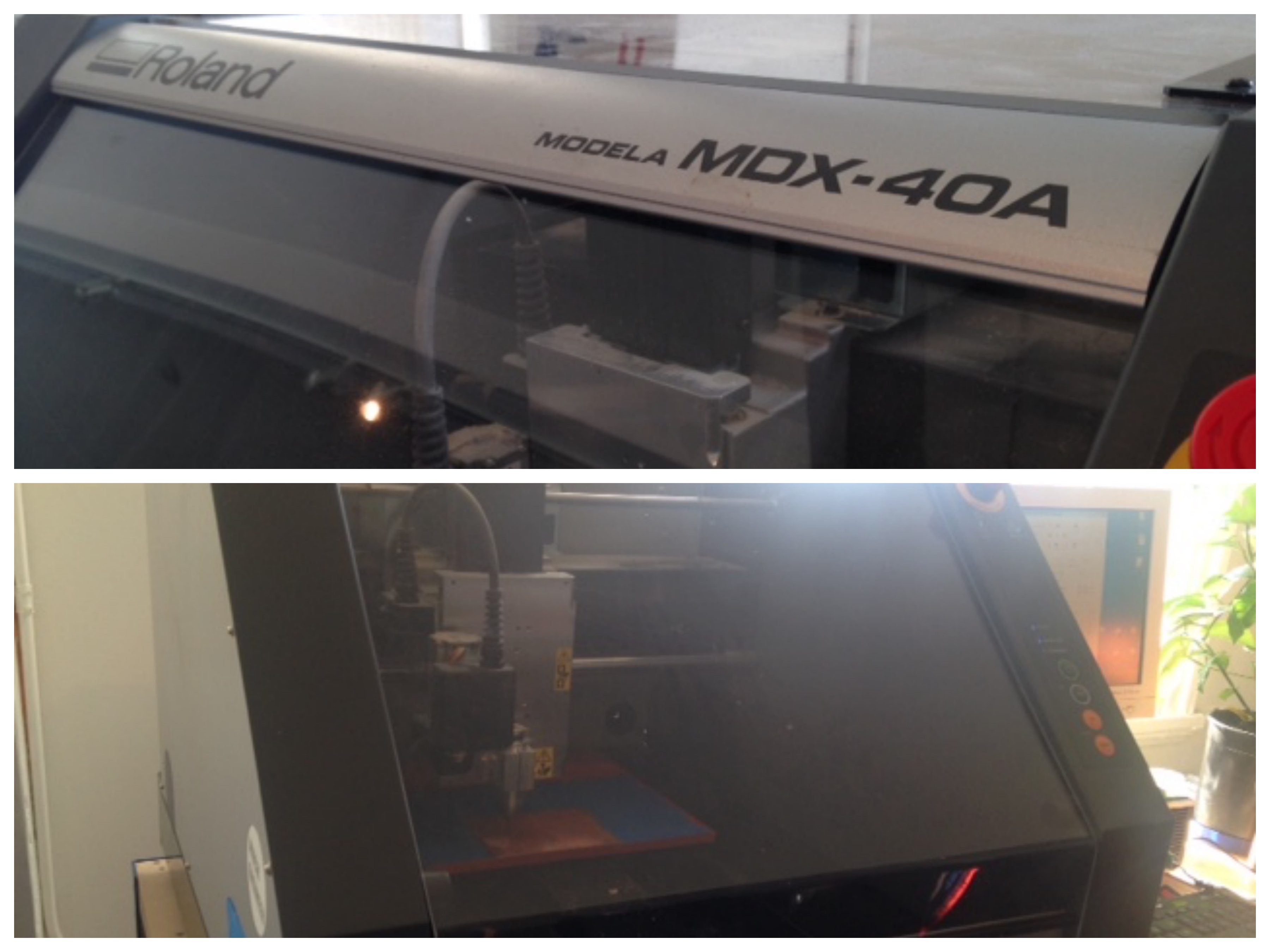
We began to have problems with the assignment from that phase. Just to put you in context, here's a picture of the machine we used and some about how we prepared it. I'd say that the milling machine that was available to us wasn't a perfect fit for beginners. To my opinion, sometimes it's not only frustrating but also unnecessary to have to concentrate that much effort on such a small part of a process and then we forget about what was really important. In this case, making an ISP and program it. I just hate that machine ! But fortunately, we did find a solution after a day wasted on this phase.
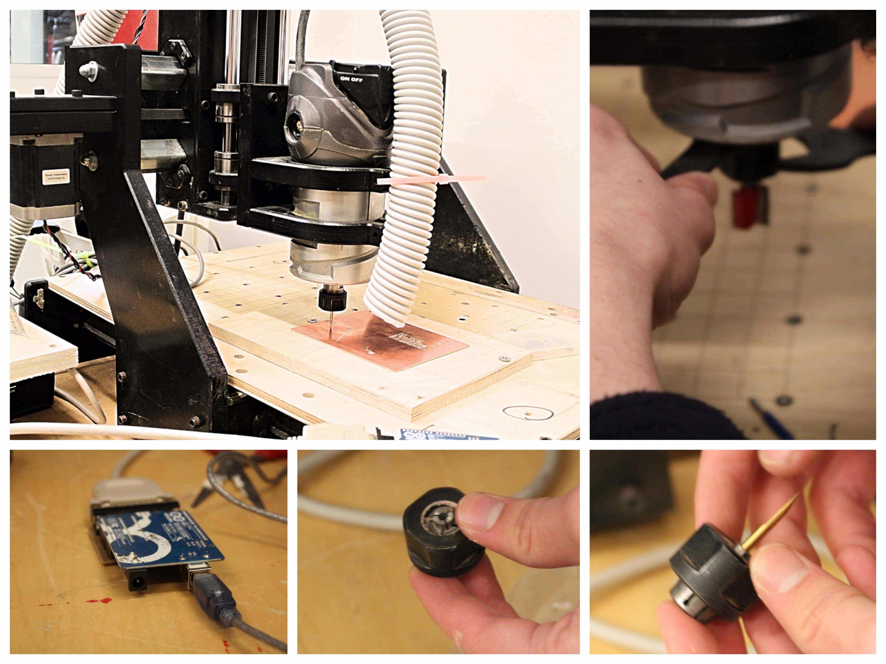
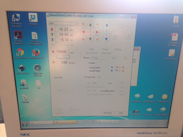
We did start with the by default settings on the FabModules. Also, we set the software that is used to control the milling machine. The steps are, even if NOT user-friendly, pretty much the same then with any kind of milling machine, that I used. First, set the X, Y, Z 0 points, import the Gcode and start the job. But, this specific software is so bad that it mixed inches with millimeters. Sometimes you press inches and it moves for a millimeter but also, sometimes you need precision movement and want to move just for a millimeter and then it moves for one inch. This kind of bug leads to catastrophe! You can break your machine trying to set the 0 point of the Z axe. We didn't break the machine but the sound that it made was pretty scary. I hate that machine ... I said it again !
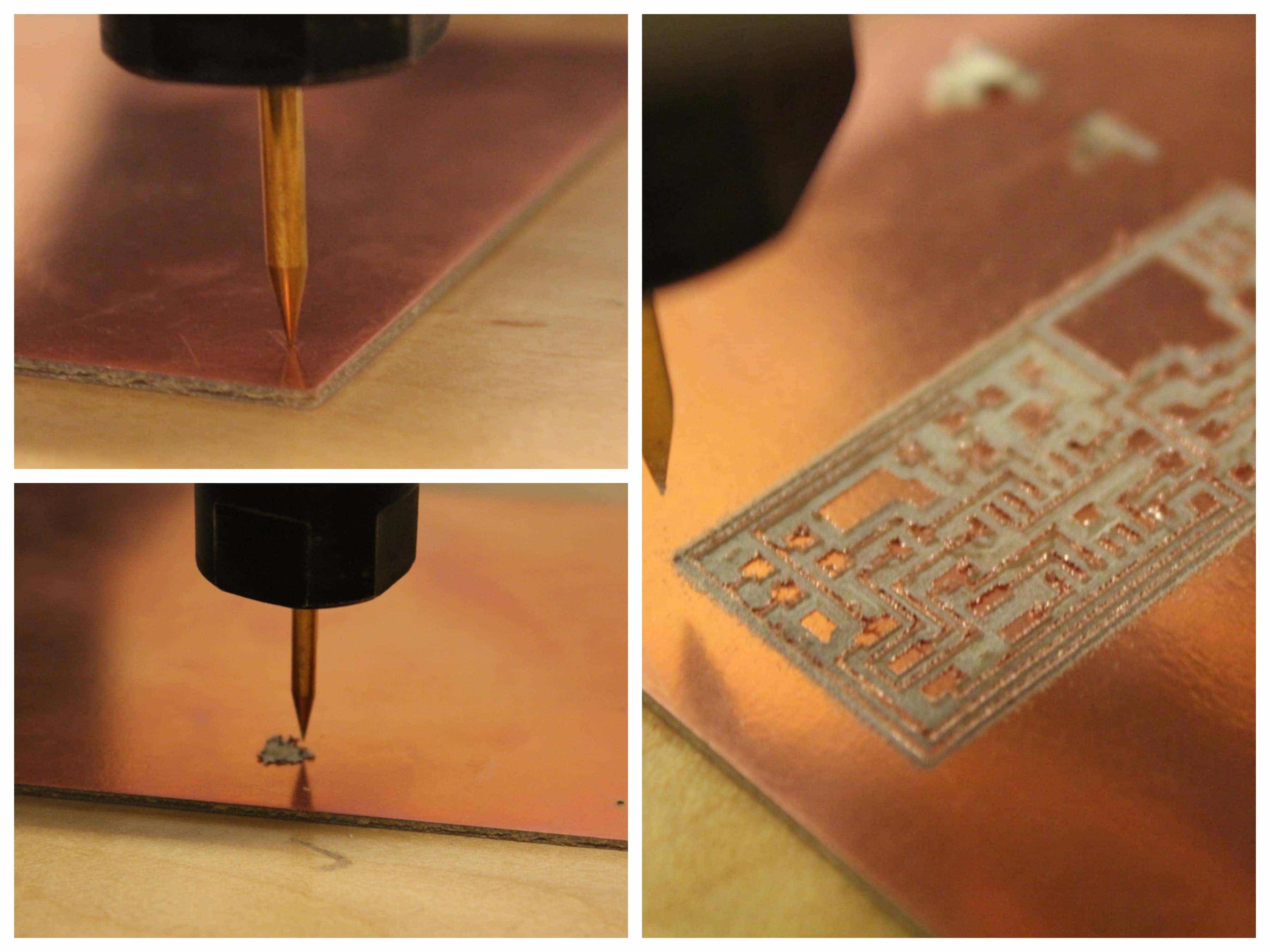
The results were bad, the engraving was too deep and also too large. I wasn't sure about what could be the problem as I've never used this specefic machine (I just used a big regular shopbot and not a lots of time). I had to keep going and find a solution or at least understand what was hapening. My fisrt conclusion was that it might be good to put the offset overlap a little higher (75%) and to lower the number of offsets a little to (2). Here's the result :
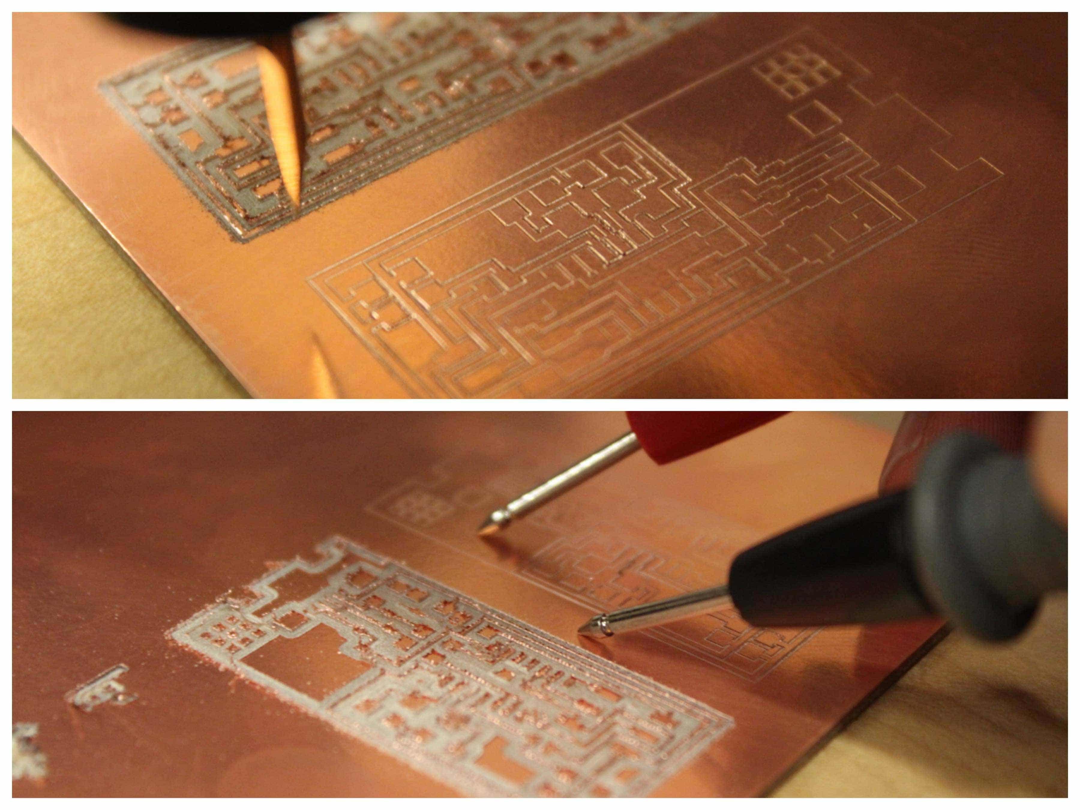
We made a test to see if the copper was off enough and nope, there was still a tiny layer because the electricity was still passing through. So, we continued our experimentation. This time, we put the offset overlap a little lower, just in between our two attempts (60%) and the offsets a little higher (3). We thought that if the first one was too large and too deep and the second the opposite, we'd be good with that setting. Here's the result :
It was still as shitty as the others. The test showed that the electricity was still passing through but also, we realized that the engraving wasn't the same size all over the board. THAT A COMPLETE DIFFERENT PROBLEM! Now we have to look at the bed level! So, we decided to try to find the most leveled part of the bed to be able to have a nice cut. We tried for about 3 hours I would say. Nothing worked and I got very frustrated, to say the least. So, I called my instructor Raphaël Demers to see if I could go see if I could go see him at "Le Fab Lab du PEC". Of course, I could! I began the process again. I prepared the file with the standard settings as Raphaël suggested. I brought the file to the machine. Well, take a look at this machine!
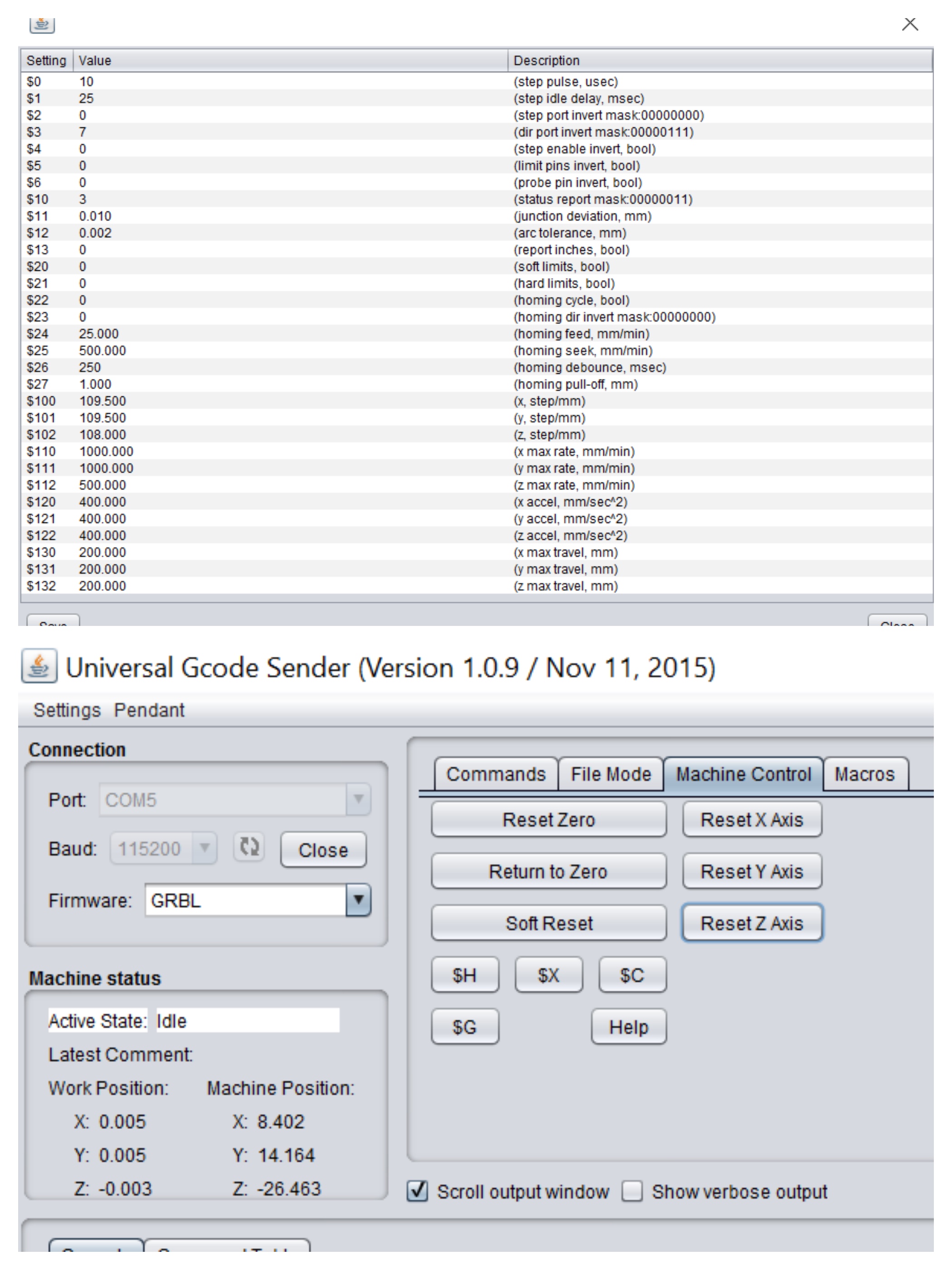
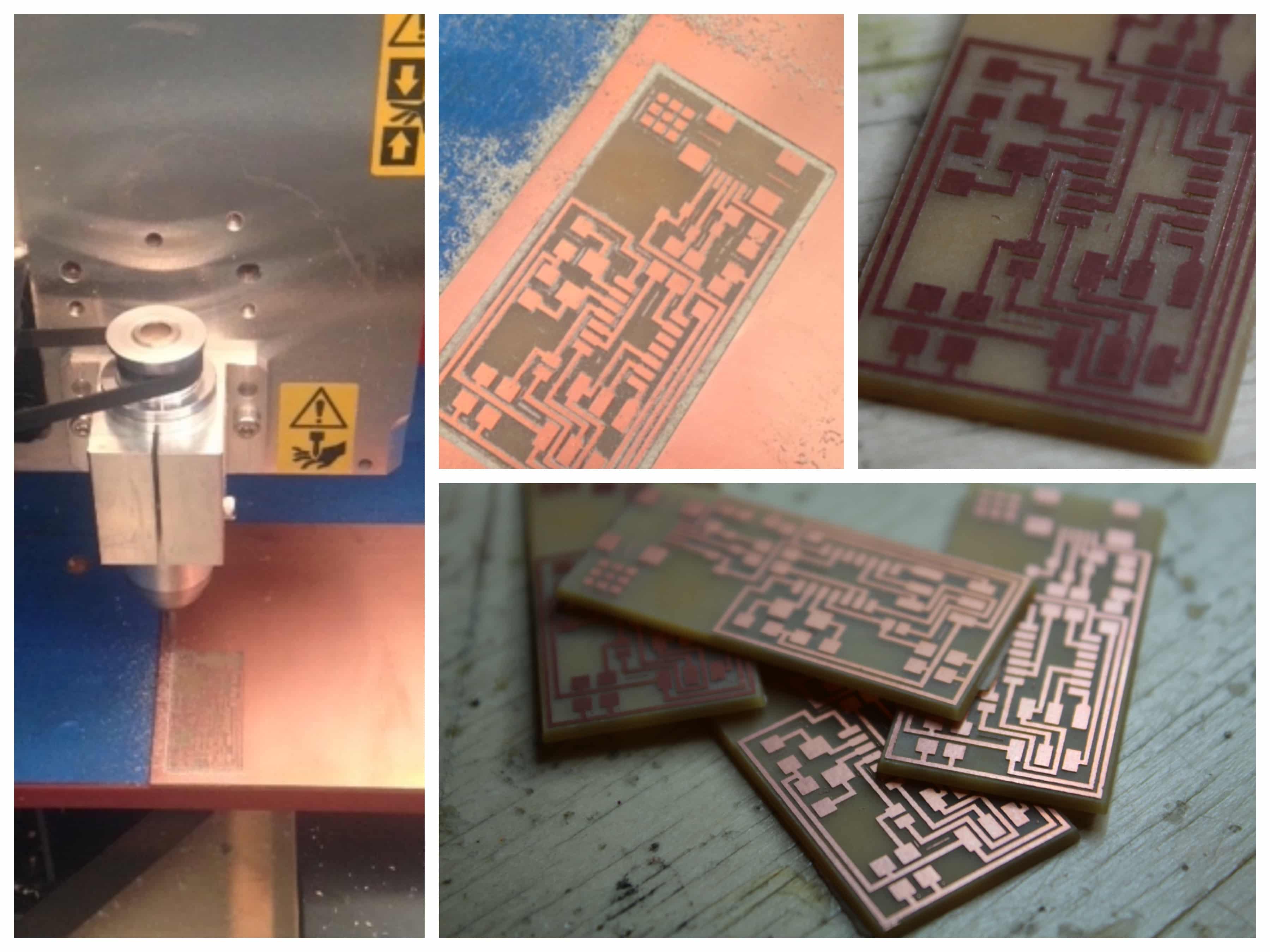
He showed me how to install the tool, to well fix the copper plate and how to set the machine with the owner software (Sorry for the bad photo, but I only could take a cell phone pic of the screen).
Then, we started to engrave and cut the PCB's. Everything went well without any problems. I have to say to it's a beautiful process to look at ! I loved to watch to tiny layers of copper getting peeled off. I made 4 of them just in case things would go wrong for the next phases. The look pretty nice to little PCBs !!!.
Soldering the components
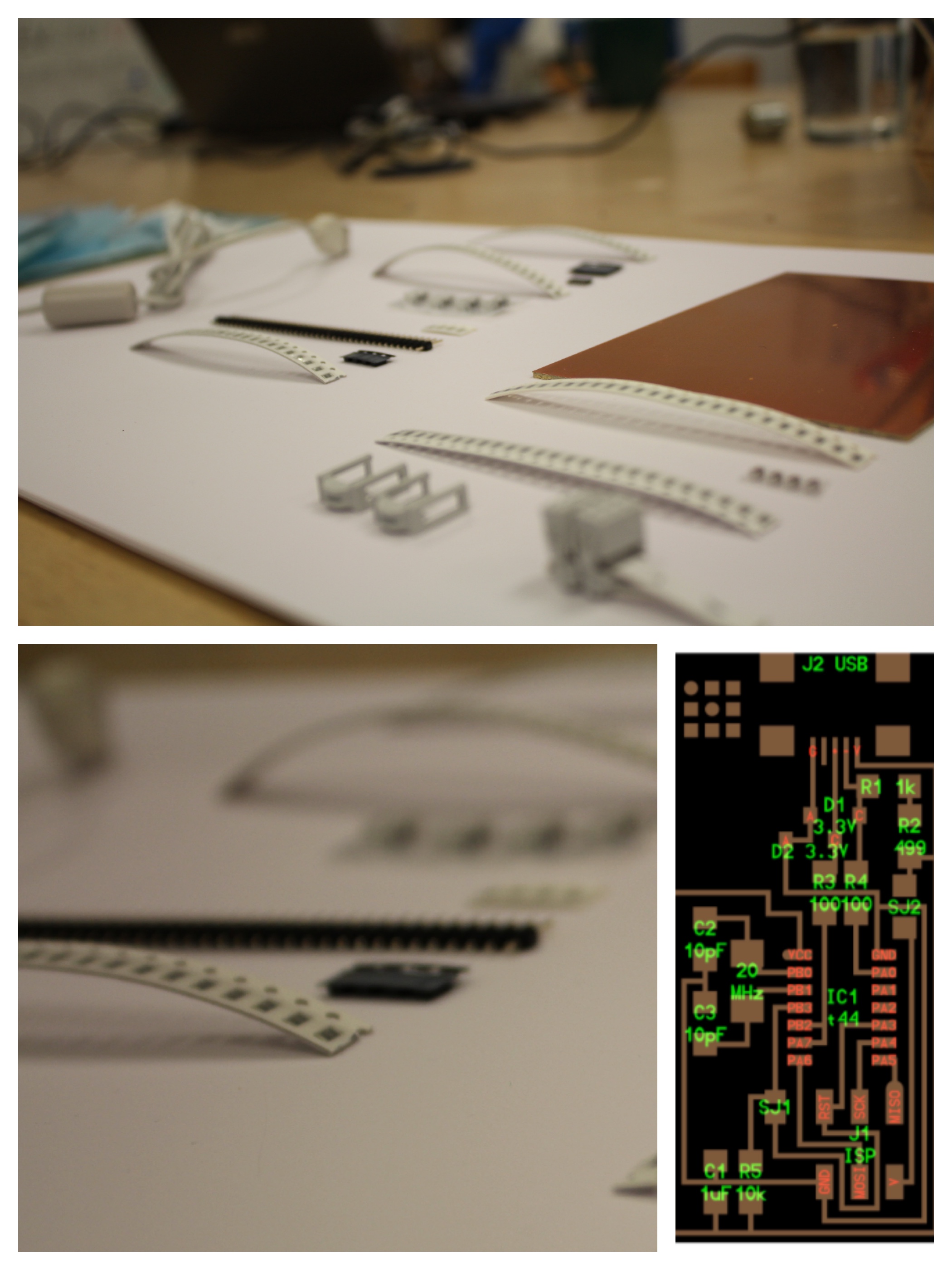
I ordered the component for me and my FabAcademy partner a while ago but, as I'm a beginner in electronic I didn't mind not to open the boxes, I wasn't that exited about it yet. When I opened the box ...
There was a nightmare in it !!! WHAT THE HELL ARE THOSE TINY COMPONENTS ! WTF is wrong with you guys !
I was a bit discouraged and then, my partern told me in regional meeting that we could pratice because I bought a pratice board a long time ago. So we did pratice.
It was a good exercice in a way but yet, as we kept going I realized that the board has a texture that wouldn't allow the tin to stick on it. I guess that to pratice your dexterity it isn't that great. Anyway, to pratice id still better than nothing.
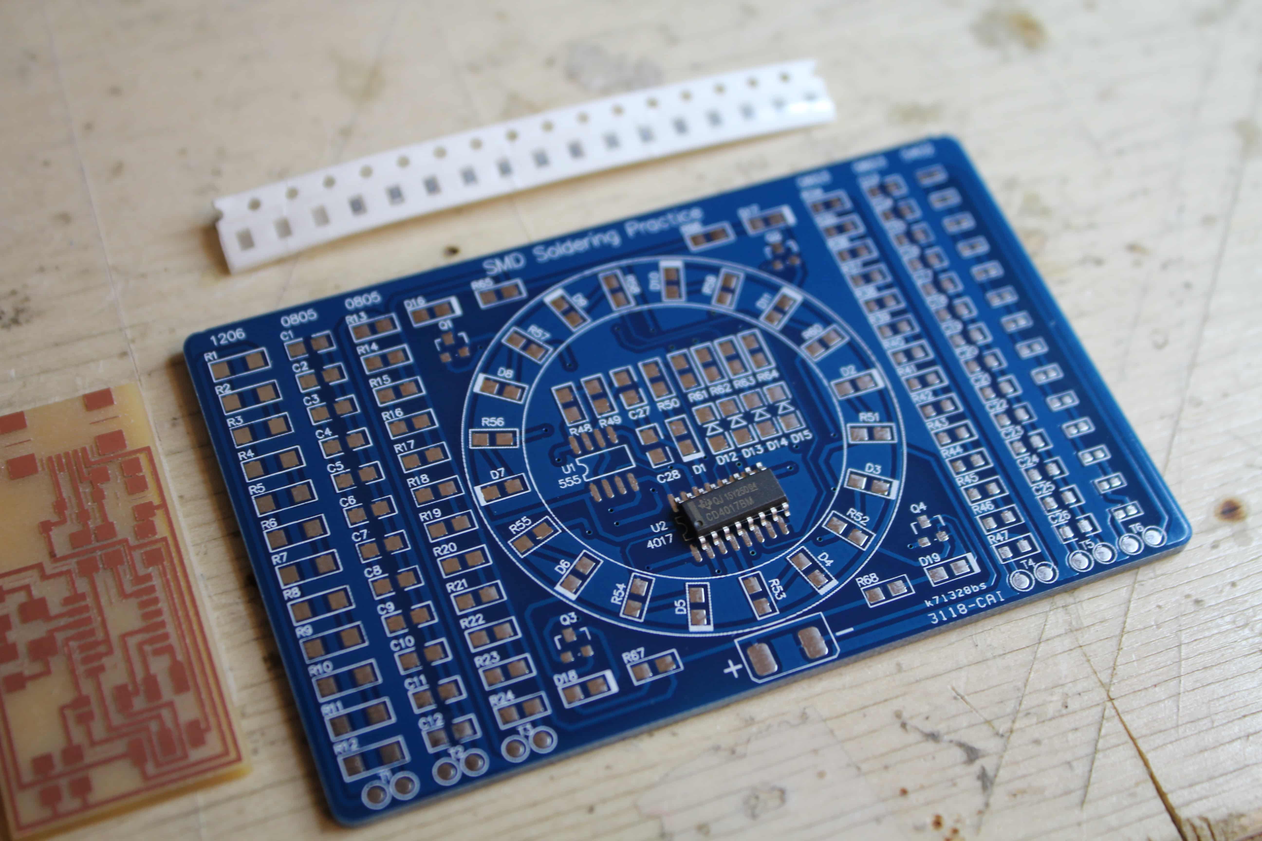
At some point, I had to start ...So I put all the pieces on a sheet of and looed at the board's plan.
Then, I began to solder the components. I burned one of my board so I did the work again ... The problem was that the iron was too hot, soI lowered the temperature. I started again without major problems. Here's ome picture of the process and the final result.
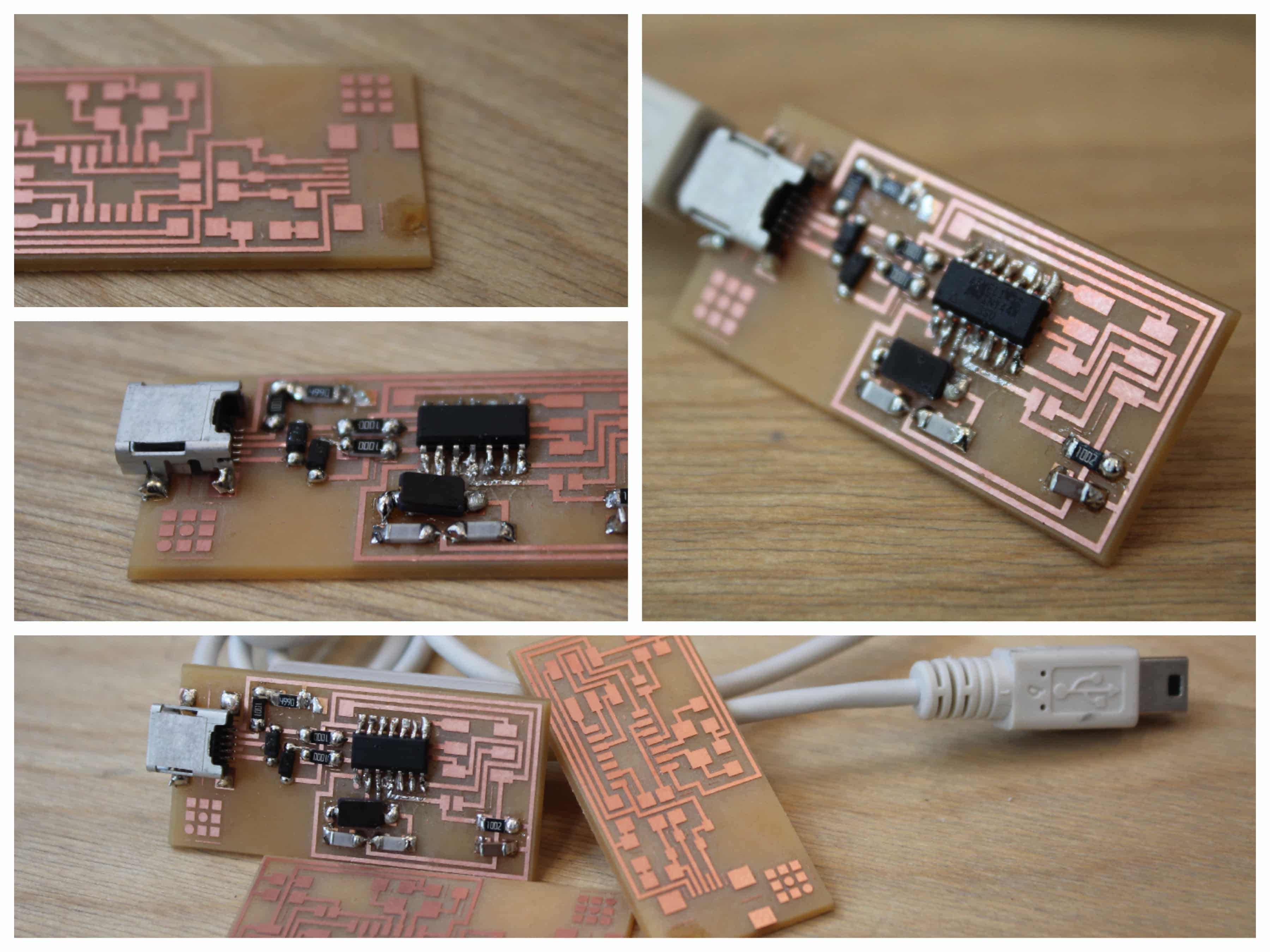
I was very proud even if the solders looks like shit.
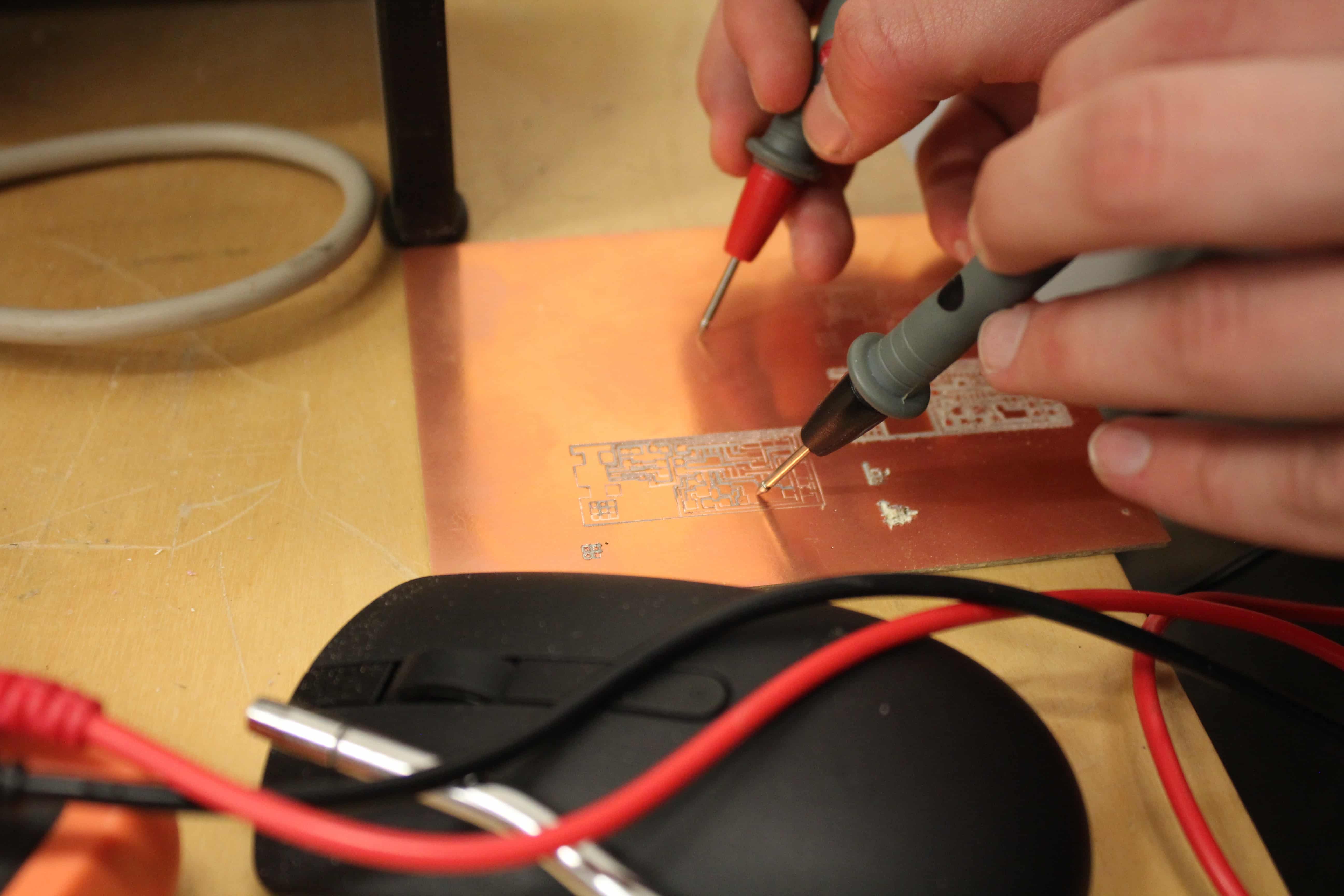
I made the test to connect the ISP in my computer to see if it tells me that it take too much power ... You now, as the tutorial proposed to see if there's some shorts.
Programing the ISP
This is where the nightmare really began and made me want to throw every by the window. I have to say that there is not a lot of resources if you fail that phase to understand what's happening so it was very, but VERY, frustrating. I guess other people in other years had a similar problem with programming the damn thing but there are so many profiles and website that with the random student button the chances that you can find another person with the same problem are very low. To be honest, this week made me be very late on all others electronic weeks. Well, enough with all that negative talk and let's see what happened.
First try
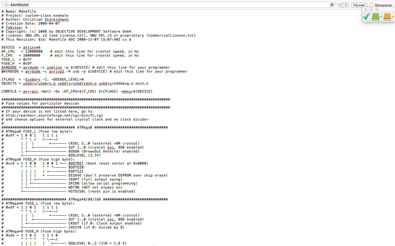
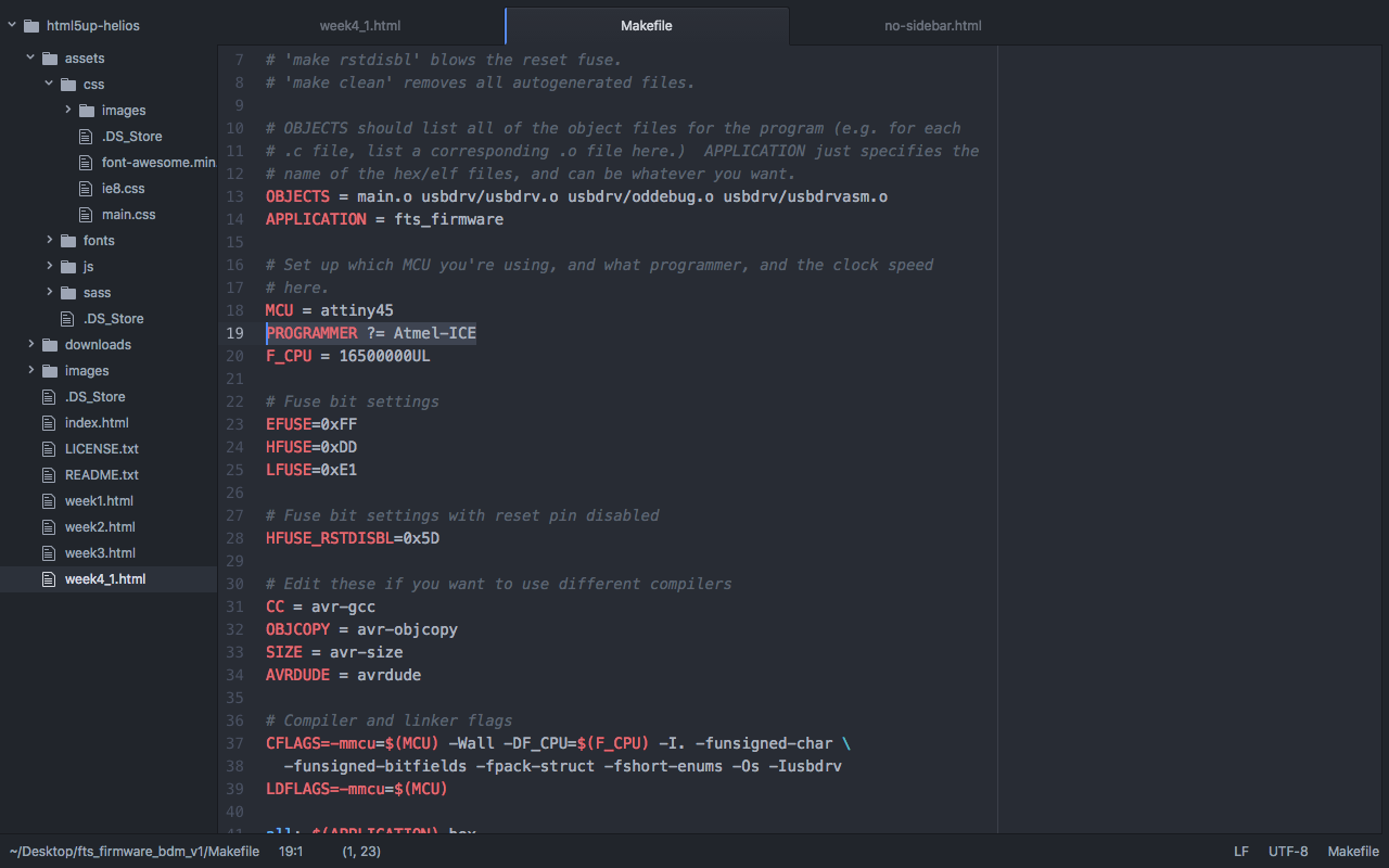
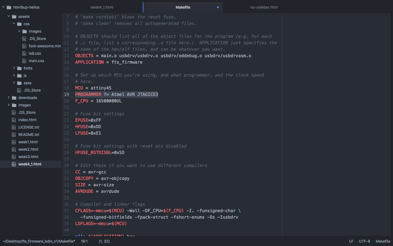
I followed the tutorial available for this phase of this week assignment. So, I installed the necessary software for AVR Programming; I pluged it on my computer from one side and to the programmer with the 6 pins header. I used a AtmelICE as a programmer; Edit the Makefile, and I made the changes in the code.
Then, I followed the other steps to program the ISP till I get the right positive message. And there you go in steps :

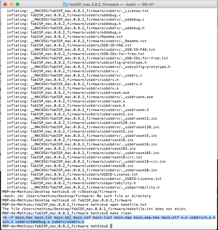
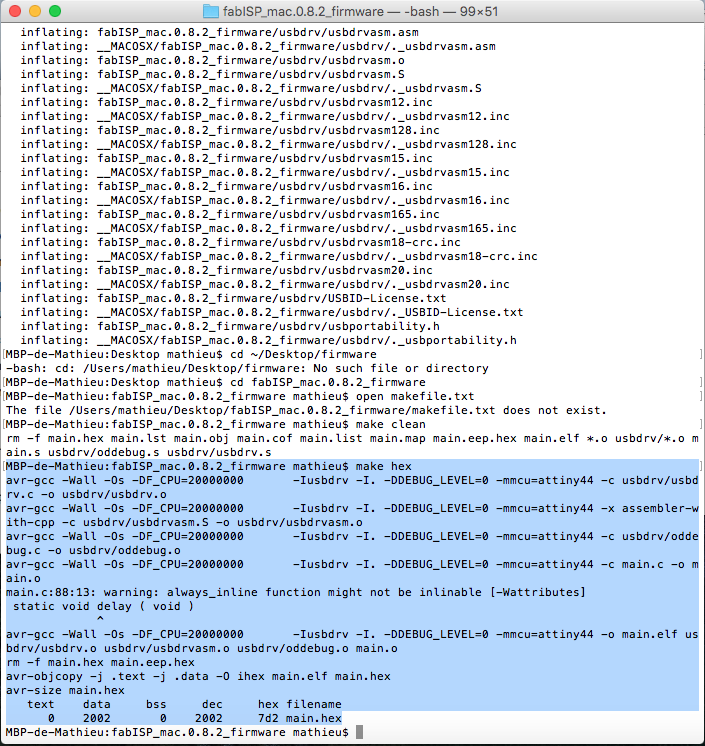
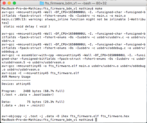
And then yay!