
Tapan
Betai

2016
Week- 8 Embedded programming
This assignment sounds difficult initially, actually i am not from electronics background and hence i found atmega 328 hard for soldering and then for programming.
Workflow:
- choosing a board and a circuit
- milling and cutting the circuit
- programming the circuit to do anything
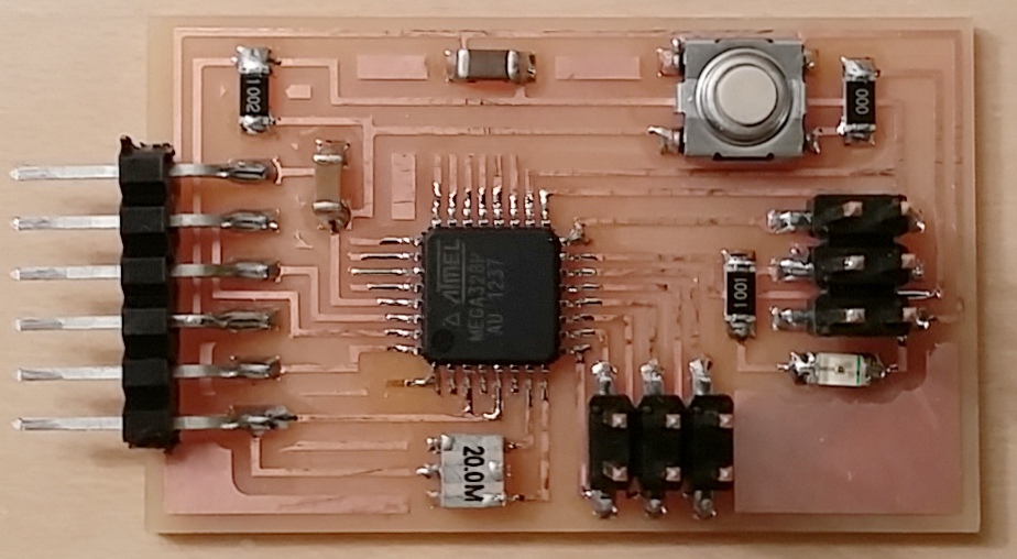
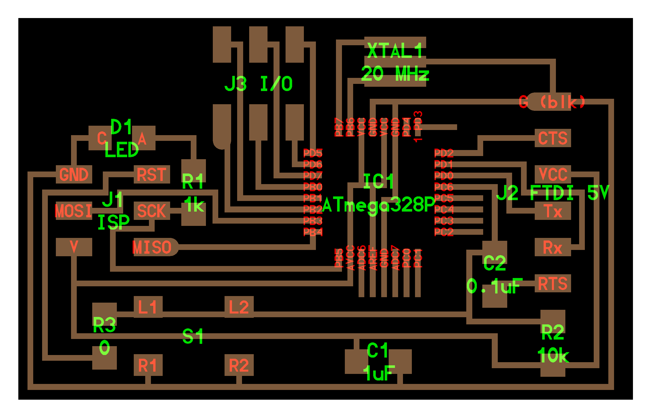
Starting with arduino circuit in which ATMEGA-328 is used.
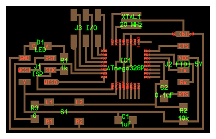
Components of the circuit
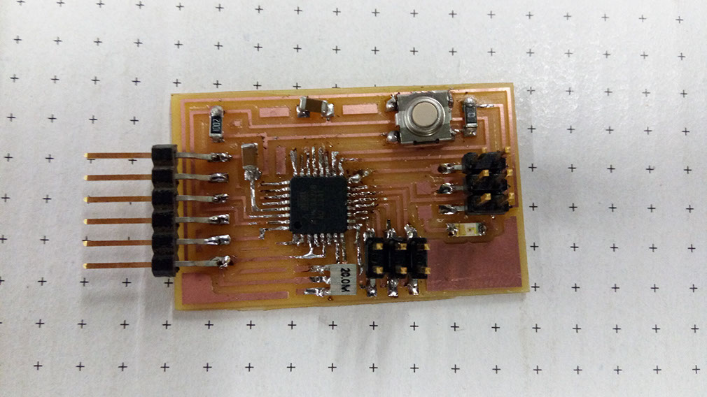
Board
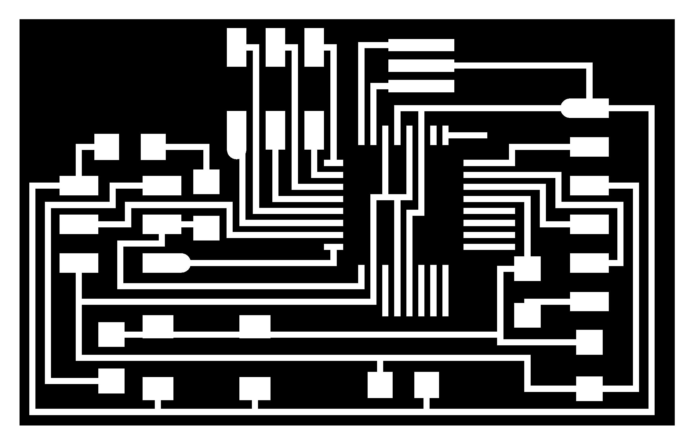
traces
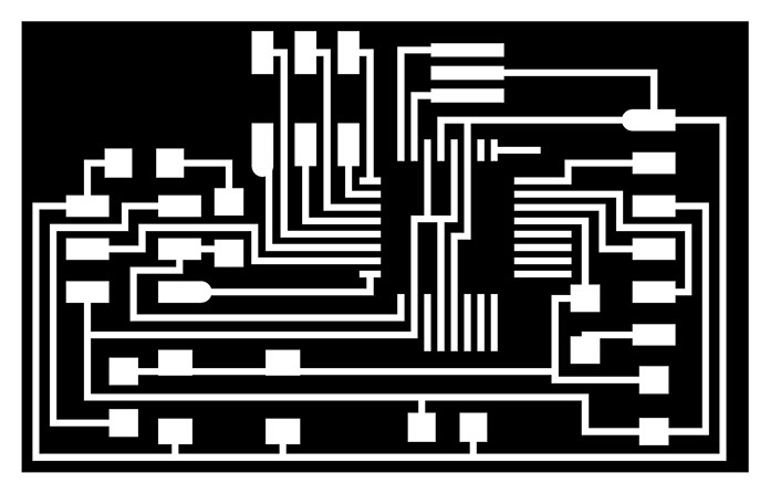
Cutting path

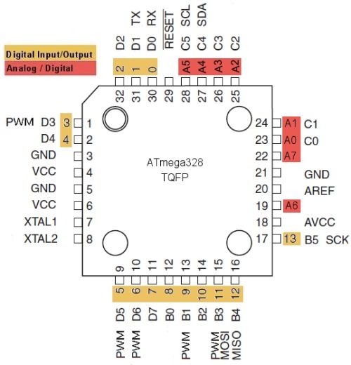
Image for understanding of the pin for analog and digital pins

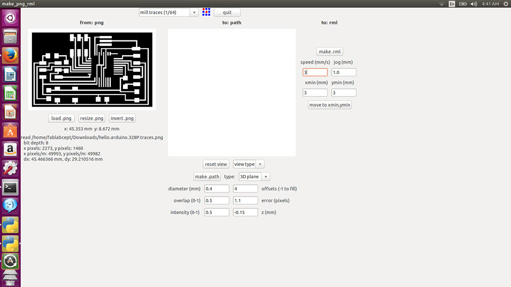
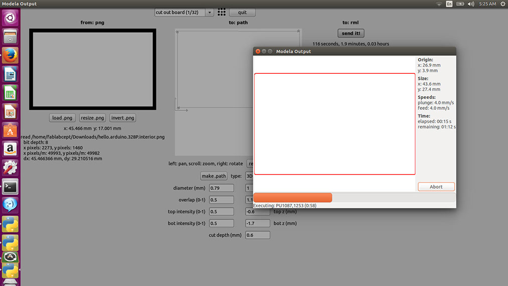
Starting with milling the circuit in -Fab module software
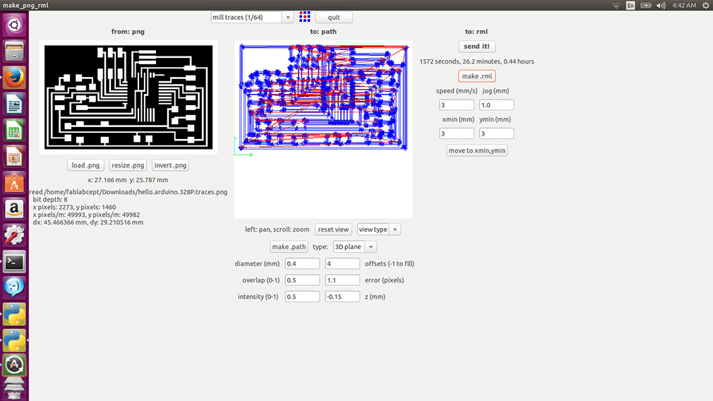
Making the toolpath using the settings for 1/64" bit
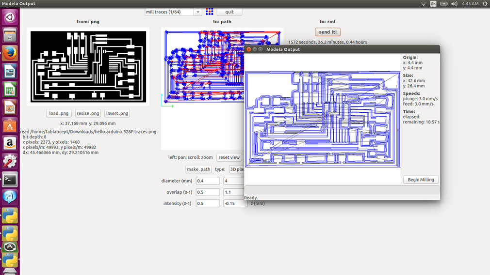
Sending the code to the machine
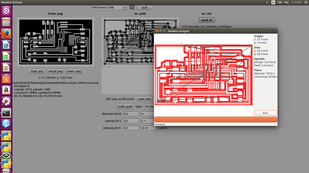
When milling is done,screen shows something like this
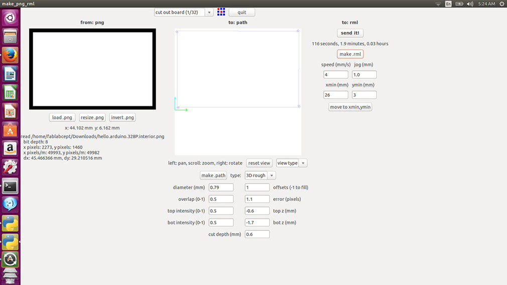
Cutting toolpath of the circuit
Cutting toolpath running
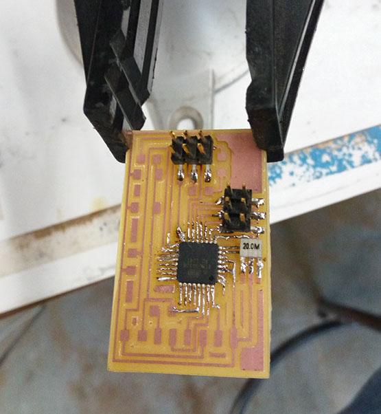
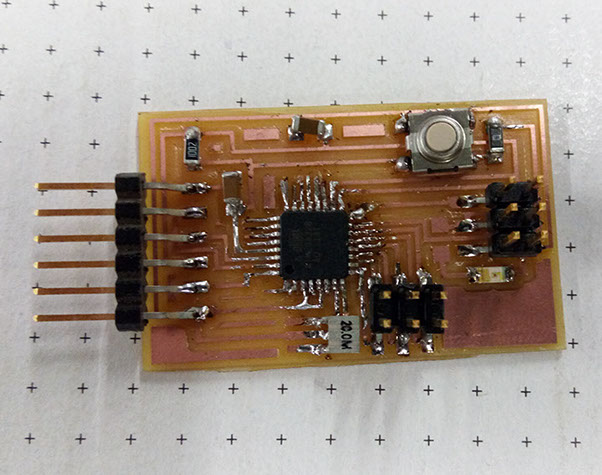
Soldering the circuit with the following components
- atmega 328
- 0.1 micro faradey capacitor
- 0 ohm resistor
- button
- LED
- 6-pin headers
- 20 Mhz clock
- 10 K ohm resistor
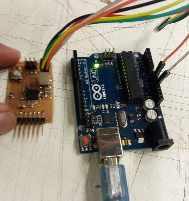
Connecting the circuit using arduino.
refer week-11 link for how to program using an arduino
link;
http://archive.fabacademy.org/archives/2016/fablabcept/students/466/11.-input-devices.html
Now our circuit is connected to the our board and we can use the board.
Additionally i have uploaded bootloading code from arduinoand then i have uploaded the code for blinking
now i am just giving power through arduino as shown in the image
in this page i am having a trouble while uploading the video to this page hence i am putting a link.
Please refer following link:
https://www.youtube.com/watch?v=CDTlcHUmB4U&feature=youtu.be
Here i have made this circuit stop blinking when i am pushing the button.
Code to upload:
//
//
// hello.button.45.c
//
// button hello-world
// 9600 baud FTDI interface
//
// Neil Gershenfeld
// 10/31/10
//
// (c) Massachusetts Institute of Technology 2010
// This work may be reproduced, modified, distributed,
// performed, and displayed for any purpose. Copyright is
// retained and must be preserved. The work is provided
// as is; no warranty is provided, and users accept all
// liability.
//
#include <avr/io.h>
#include <util/delay.h>
#define output(directions,pin) (directions |= pin) // set port direction for output
#define input(directions,pin) (directions &= (~pin)) // set port direction for input
#define set(port,pin) (port |= pin) // set port pin
#define clear(port,pin) (port &= (~pin)) // clear port pin
#define pin_test(pins,pin) (pins & pin) // test for port pin
#define bit_test(byte,bit) (byte & (1 << bit)) // test for bit set
#define bit_delay_time 102 // bit delay for 9600 with overhead
#define bit_delay() _delay_us(bit_delay_time) // RS232 bit delay
#define half_bit_delay() _delay_us(bit_delay_time/2) // RS232 half bit delay
#define input_port PORTB
#define input_direction DDRB
#define input_pin (1 << PC6)
#define input_pins PINB
int main(void) {
//
// main
//
// set clock divider to /1
//
CLKPR = (1 << CLKPCE);
CLKPR= (0 << CLKPS3) | (0 << CLKPS2) | (0 << CLKPS1) | (0 << CLKPS0);
//
// initialize pins
//
set(input_port, input_pin); // turn on pull-up
input(input_direction, input_pin);
//
// main loop
//
while (1) {
//
// wait for button down
//
while (0 != pin_test(input_pins,input_pin))
;
digitalWrite(PB5, HIGH);
//
// wait for button up
//
while (0 == pin_test(input_pins,input_pin))
;
digitalWrite(PB5, LOW);
}
}
I wanted to turn on and off the LED on the Arduino Circuit with ATMEGA328 with a button.
Following instructions will help you:
- Open Arduino software
- connect arduino UNO
- upload code of Arduino as ISP from examples
- now connect arduino that we have made with arduino UNO with the pins that program of Arduino ISP shows
- Now from tools select atmega board
- chip as atmega 328
- choose internal clock of 8 MHz
- and choose arduino as ISP in tools -> programmer
- Copy the code from previous paragraph
- paste it in the arduino window
- upload it
- after uploading it successfully, remove all the pins other than ground and 5V.
- Now when i presses the button on my circuit LED turns off and when i leave the button it again blinks