
Tapan
Betai

2016
Final Project: Fab-360
360 photography in a FAB way (compatible with any Device having "Good" Camera)

Objectives:
- Compatible with with mobile phones, tables or digital cameras.
- Light weight
- Cost effective
- Accurate images even with mobile phones
- Patching of the images becomes more easy
- can be an open source design
- simple basic electronics
- No human efforts needed
- Small in size
This is one the project which i always wanted to work on for better precision with less devices and which can be used with any of the basic devices which one have.
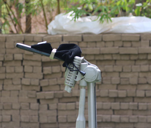
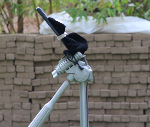
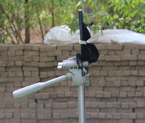
So as shown in images below, there is going to a stand on which you can mount any of your camera devices and which works on 3- degree of freedom. which can be rotated as any other camera stand can but here the rotation will be automatic.
We have to work on timing to take the images and angles involved, devices used, image compositions, rendering,etc.
With the help of this stand one can create high resolution 360 degree image of any space with less human efforts and with greater accuracy.
Anyone can get clean perfect 360 images with the help of this stand either a 10 year child or a granny who loves to click picture.
I am going to use simple technology in this device but i have to work a lot on timing of image taking and with different camera technologies.
Starting at week-2
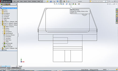
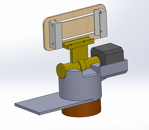
Side view containing housing which can rotate in vertical and horizontal planes with two different motors.
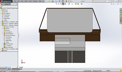
Sectional view showing different parts in different colors which can be made of either metal or Plastics
Competitors
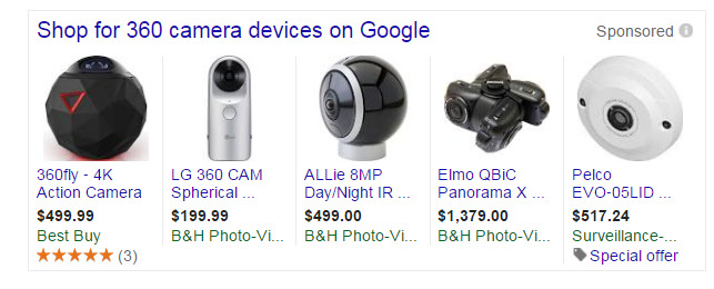
As you can see in the image, none of the device is below 350 USD.
This is a very good idea to make something very cheap and accurate.
Starting with Design
Hardware was needed to be rotated in any of the plane and it needed two stepper motors for this kind of rotation.
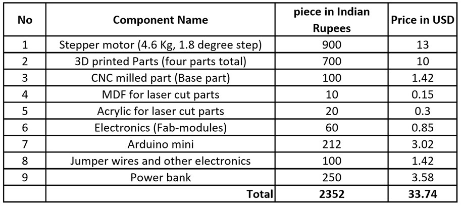
Components needed
Fab-360 can be made in less than 40 USD(Price may vary with different currency, but will not exceed 40 USD).v
3D Printed Parts
1. Motor and electronics housing
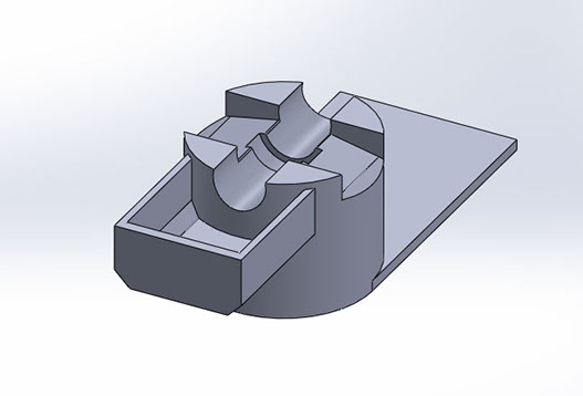
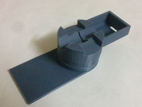
A part for housing one of the stepper motor, rotational part for holding the camera device and Electronics.
It took 12 hours to print this part in ultimaker 2.
Supports were generated in the machine due to complexity and they were removed and then the surface was finished with hands.
Infill for this part is given 60% for better stability and strength.

2. Camera rotation and mounting
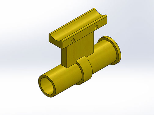
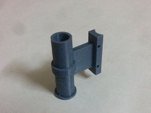
This Part fits and rotates inside the first part.
It holds mobile phones with any suitable size.
One end Houses shaft of the motor.
here images shows layer printing of the part in ultimaker 2.
Supports were removed and surface was finished by hands
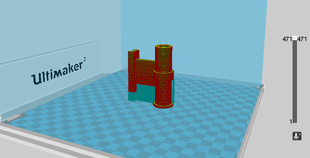
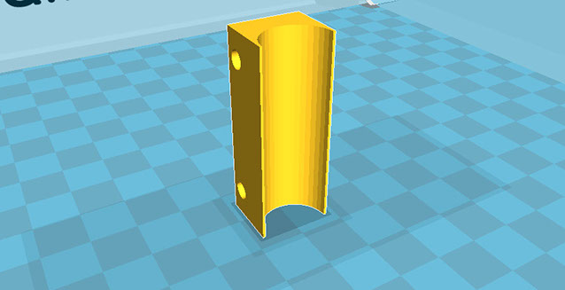
3. Mobile holding clamps
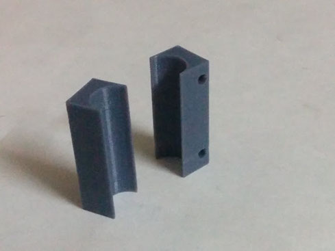
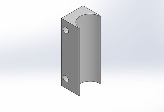
This Part was made to hold the mobile phone from other than bottom sides.
Part is 3d printed as it does not need much strength to withstand any weight.
Infill density is set at 40% for this part.
It can be 20-40% for this part.
Two of these parts are used as it will be hold from two opposite sides.
CNC milled Part
4. Base- motor housing
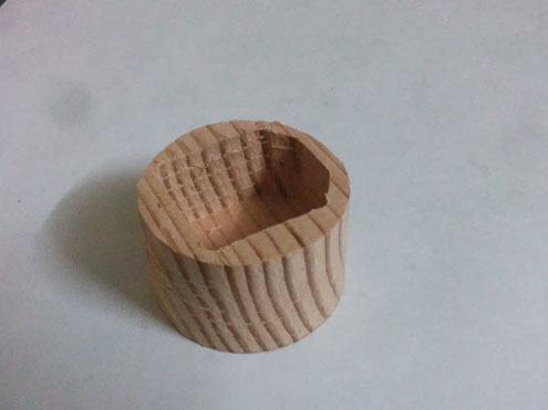
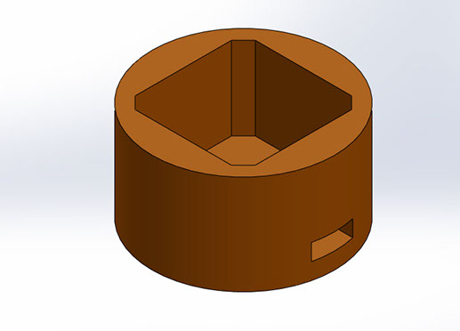
This Part is made of wood as it needs to take all the weight of hardware and the mobile.
It also houses a stepper motor which rotates everything in horizontal 360 direction.
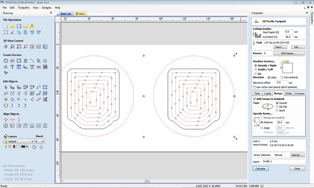
It was made in shopbot CNC machine.
Image shows path, geometry and settings for machining.
I made two same parts to save time incase of failure of one.
Laser cut parts
5. MDF support for Mobile phone
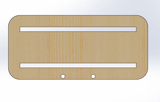
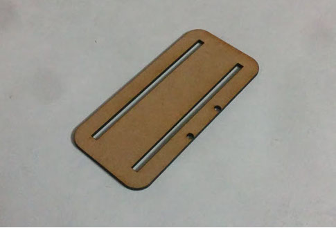
This one part done on epilog laser mini.
I needed more density for this part as this part is more in length and there were chances of bending of the part if it is not solid or 3d printed.
3d printed part takes lot time for printing and laser cut part takes only two minutes.
It saves a lot time, electricity, Material.
It has guides to support holding clamps from two sides therefore you can use use different mobile phones and they can be clamped according to their different sizes
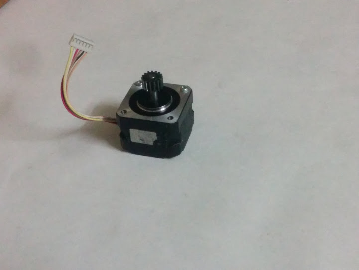
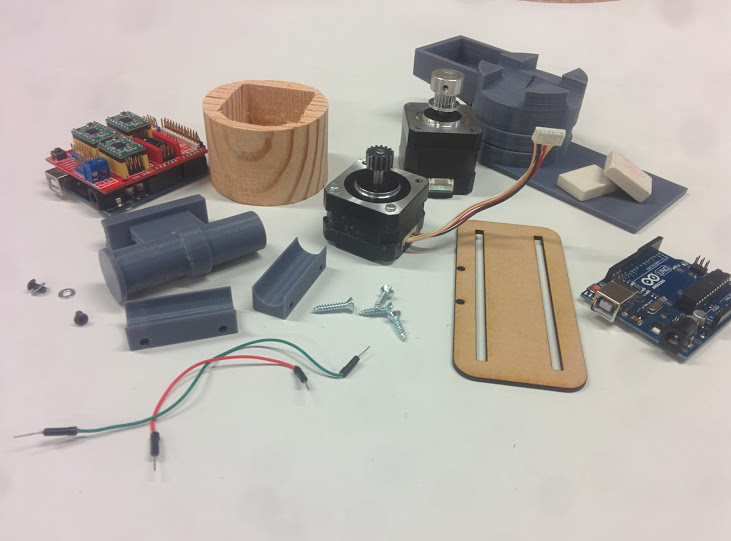
Ready Components
6. Stepper motors
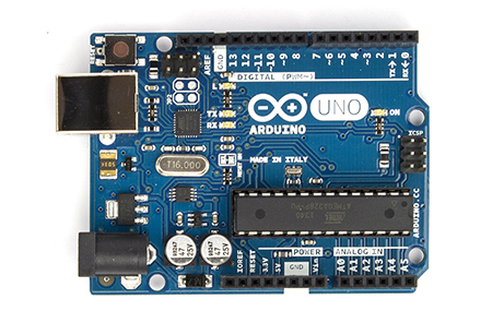
7. Arduino Uno
8. Stepper motor divers
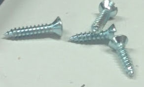
9. M3 screws and Hard rubber

All the needed components
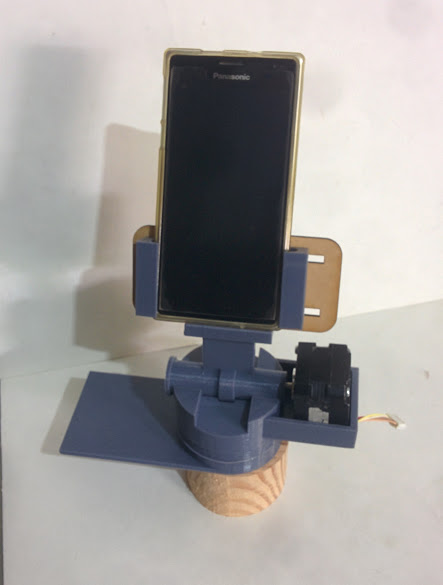
Assembly
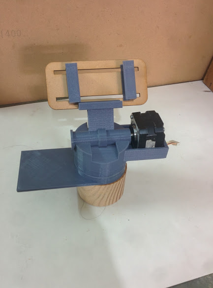
Exploded view
Assembled with mobile phone
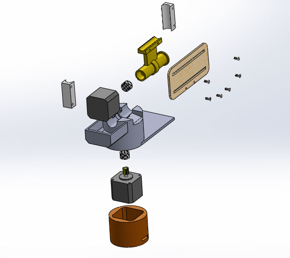
How to assemble all the components to complete the hardware
Logic After coding
I need all the angles, frame of references, number of photographs to be taken in the position, etc.
We started with taking 360 photographs with mobile. I have some friends who are currently working on virtual reality.
Prahar, Richa and Rudra helped me out with angles and all other things i needed.
Taking reference images for finding angles
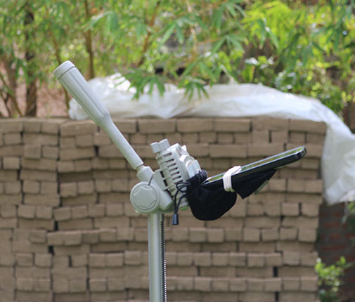
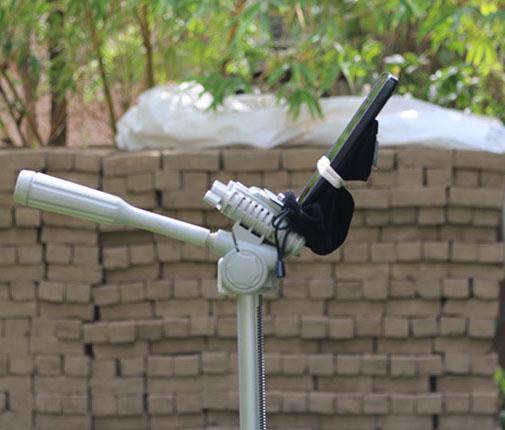
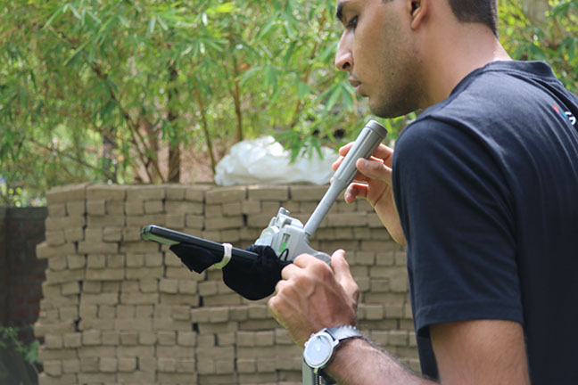
In Above section we took all the vertical angles with the same reference window and then measured all the angles in vertical frame. Then took number of images in the horizontal frame with which we can make a good 360 image without much patching of images. We used google camera which give auto-patching option and which takes all the images automatically without human efforts.
Here you can see team helping me out with virtual reality part.
Angles for vertical motion
zero is the mean straight line... mobile will stay straight in this position... 3rd line in vertical is zero angle.
0 3rd line
+43 2nd line
+69.5 1st line
-36.5 4th line
-72.5 5th line
for horizontal motion.
vertical angle number of pictures
line to be taken
1st line 90 -4 times
2nd line 36 - 10 times
3rd line 27.69 - 13 times
4th line 36 -10 times
5th line 90 - 4 times
Above stated is the angles for coding
First the camera will take angles in the
3rd line
then 2nd line
then 1st line
then 4th line
then 5th line
when you are using nexus phones you can use this codes, but when you are using a different mobile phone first
- first download google camera
- start 360 camera.
- take 360 image with hands and measure time delay between taking the photograph
- edit the time delay in the code from the files while uploading.
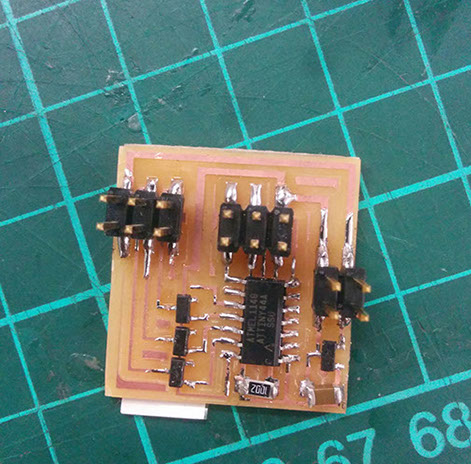
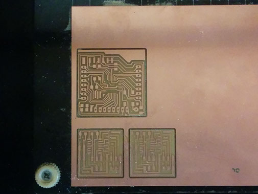
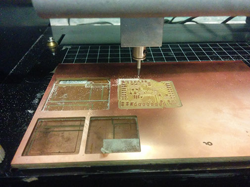
Electronics
Mill tracing of stepper motor drivers and fab-duino
Outline cutting of circuits
Soldering the components
circuit done
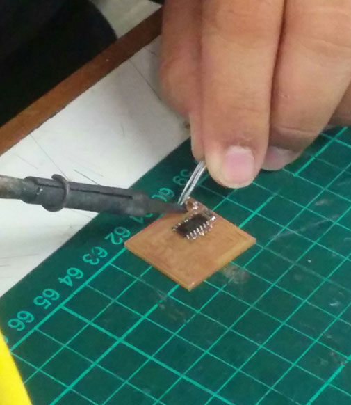
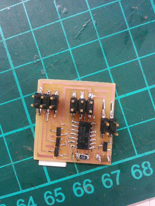
Components needed for stepper motor driver:
- attiny44
- 1 micro Faraday capacitor
- 1 10K resistor
- 2 6-pin headers
- 1 4-pin header
- 5 5V regulator
Assembly:
you can watch this video for assembling all the components
Code for horizontal stepper:
#include <Stepper.h> //Library for Stepper motors
#define STEPS 100 //no. of steps
//define an instance of Stepper class with the pin nos. and no. of steps
Stepper stepper(STEPS, 8, 9, 10, 11);
void setup()
{
stepper.setSpeed(30); //setting speed of the motor in RPMs
// For line 3
for (int i = 0; i < 13; ++i)
{
stepper.step(15);
delay(1500);
}
delay(2650);
//For line 2
for (int i = 0; i < 10; ++i)
{
stepper.step(20);
delay(1500);
}
delay(2650);
//For line 1
for (int i = 0; i < 4; ++i)
{
stepper.step(50);
delay(1500);
}
delay(7000);
//For line 4
for (int i = 0; i < 10; ++i)
{
stepper.step(20);
delay(1500);
}
delay(2650);
//For line 5
for (int i = 0; i < 4; ++i)
{
stepper.step(50);
delay(1500);
}
}
void loop()
{
}
Code for Vertical stepper:
#include <Stepper.h> //Library for Stepper motors
#define STEPS 100 //no. of steps
//define an instance of Stepper class with the pin nos. and no. of steps
Stepper stepper(STEPS, 8, 9, 10, 11);
void setup()
{
stepper.setSpeed(30); // setting speed of the motor in RPMs
delay(33000);
stepper.step(24); //moving 43.2 degrees
delay(28000);
stepper.step(15); //moving an additional 27 degrees
delay(15000);
stepper.step(-39); //returning to the origin
stepper.step(-24); //moving 43.2 degrees in the negative direction
delay(28000);
stepper.step(-15); //moving additional 27 degrees in the negative direction
delay(15000);
stepper.step(39); //returning to the origin
}
void loop()
{
}
when you are using nexus phones you can use this codes, but when you are using a different mobile phone first
- first download google camera
- start 360 camera.
- take 360 image with hands and measure time delay between taking the photograph
- edit the time delay in the code from the files while uploading.
Final Presentation Video
3D Printing Files:
housing for stepper motor bigger one
second motor housing -2nd part
CNC milling files:
base part profile for CNC Milling fab-360
Pocket file for CNC milling fab-360.sbp
Profile cut shopbot file for CNC milling fab-360
Laser cutting files:
Codes:
Horizontal direction motion Stepper