Here I show what each line does in my blink with button program.
Click for animated picture
A C program to turn on the LED when the BUTTON is pressed on the hello echo board.
Both files, zipped C file make file
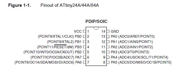
In order to use a microcontroller there are a few key things we need to find in the data sheet in order to get started.
To design a schematic for the microcontroller we need to know:
To use the microcontroller we need to know
To see how to set the Pin and Port registers, please read my commented code here.
UPDATE: For Output devices week I read lots in the TB6600HG data sheet in order to redesign the Satstep6600 stepper driver card. I noticed that the original satstep6600 card drew to much current for the alert diodes and didn't use correct resistance to setup the reference voltage that controls the output current from the stepper. I fixed both in my design which I ended up using for my final project.
This weeks first task was to read the 286 page ATtiny84A data sheet. I started by reading straight though most of the first parts (to page 67) and familiarised myself with what was in the following sections. Then I came back to the sheet when I needed to check something.
To keep track of terms as I learned them and what they meant I listed them as I read into the table below. I then used the table and the data sheet to make sense of the C code examples Neil provided. I went through the code line by line and made sure I understood it and wrote up explenation as comments. See the fully commented code here
| Register | "operates on very quickly" | are used to perform calculations | 32 of 8 bit registers directly connected to the Arithmetic Logic Unit (ALU), allowing two independent registers to be accessed in one single instruction executed in one clock cycle. | |
| ALU | The Arithmetic Logic Unit (ALU) The ALU is what you might also know as CPU on a normal computer | |||
| SRAM | "Stores data temporarily" | 512 bytes | ||
| DRAM | "Also for temporarly data storage, slower but bigger than SRAM" | (Does not seem to exist in the attiny) | ||
| EEPROM | "Non voletile, will persist if you turn it off" | Endurance: 100,000 Write/Erase Cycles | 512 bytes | |
| FLASH | "Harder to write, this is where my program is stored" | Endurance: 10,000 Write/Erase Cycles | ||
| Fuse bytes | "Small configuration memory" | Used to setup modes and fuctions for how it should operate. | Note that the fuses are read as logical zero, “0”, if they are programmed. | It has three fuse bytes. |
| Interupt | Makes the IC attend to stuff immidetly | Pin Change Interrupt on 12 Pins | ||
| PORT | is for outputting data I/O. | |||
| PIN | is for reading in data I/O. | |||
| Tri state | ...assume a high impedance state in addition to the 0 and 1 logic levels, effectively removing the output from the circuit. | |||
| SPI | The SPI (Serial Peripheral Interface) is a peripheral used to communicate between the AVR and other devices, like others AVRs, external EEPROMs, DACs, ADCs, etc. | |||
| PORT | is for outputting data I/O. | |||
| PIN | is for reading in data I/O. | |||
| Port pins | Each port pin consists of three register bits: DDxn, PORTxn, and PINxn. | |||
| DDxn | The DDxn bit in the DDRx Register selects the direction of this pin. | If DDxn is written logic one, Pxn is configured as an OUTPUT pin. If DDxn is written logic zero, Pxn is configured as an INPUT pin. | ||
| PINxn | The Port Input Pins I/O location is read only | Writing a logic one to PINxn toggles the value of PORTxn, independent on the value of DDRxn | Independent of the setting of Data Direction bit DDxn, the port pin can be read through the PINxn Register bit. | |
| PORTxn | When set as INPUT: If PORTxn is written logic one, the pull-up resistor is activated. To switch the pull-up resistor off, PORTxn has to be written logic zero. | When set as OUTPUT: If PORTxn is written logic one, the port pin is driven high (one). If PORTxn is written logic zero, the port pin is driven low (zero). | ||
| PUD | the Pull-up Disable – PUD bit in MCUCR disables the pull-up function for all pins in all ports when set. | Normally, the pull-up enabled state is fully acceptable, as a high-impedant environment will not notice the difference between a strong high driver and a pull-up. If this is not the case, the PUD bit in the MCUCR Register can be set to disable all pull-ups in all ports. | ||
| SPM | The device provides a Self-Programming mechanism for downloading and uploading program code by the MCU itself. | The SPM instruction is disabled by default but it can be enabled by programming the SELFPRGEN fuse (to “0”). | ||
| Lock bits | There are two lock bits which can be left unprogrammed (“1”) or can be programmed (“0”) to stop reprogramming | The lock bits can only be erased to “1” with the Chip Erase command. | ||
| Pull up resistor value for I/O pin | 20-50kOhm |
Time to try some programming
To begin playing with the code I used Brackets to open and edit the example files. I don't recommend this method for more advanced coding.
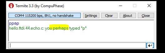
To test that everything was working as before and that I actually could modify code and get it sent to my board I changed ONE word in the hello-echo code and tried following my own instructions for programming the board and talking to it via serial.
After a minor hikkup of me not remembering to save my file first I got it working fine!
To load the board with my new program was I compiled the HEX file using the make file and uploaded it to the board. Commands:
My altered program, the alteration is highlighted.

Success! Time to try the diode or the button!
I downloaded the blink example in C with it's own makefile that Neil provided on the lecture page.
However, these are setup for the atmega328p so I need to do some tweaking if I want them to work.
I read the acdemany tutorial on makefiles
Perhaps I can just reuse the makefile if I rename and change the name in the first line after the project? I'll try it!
I see in the blink.c code that they specify another pin for the blink, I'll change it to match my schematic. I'll switch the PB5 to PA7.
#define led_pin (1 < < PB5)

It programmed ok, but didn't work!
Turns out I missed to change A to B as well. (the pin port groups)
IT WORKS! I tested powering it via both the FabISP and the FTDI cable.
Click for animated gif

:1000000010C017C016C015C014C013C012C011C054
:1000100010C00FC00EC00DC00CC00BC00AC009C07C
:1000200008C011241FBECFE5D1E0DEBFCDBF02D096
:1000300019C0E6CF80E886BD16BCDF98D79A24EFBA
:1000400031E0DF9A88EE93E0F9013197F1F70197FB
:10005000D9F7DF9888EE93E0F9013197F1F701972E
:08006000D9F7EFCFF894FFCFB0
:00000001FF
C file
makefile
Finding the right port adress for the button:

Idea: Try interupts by finding ref file and mixing code. But get coding envonment going first
After some hacking I decided this will take forever to build on my own, I rather read someone elese code and try to understand what it does.
I downloaded the C file from Thorbjorn Thorgeirsson a 2016 student and used his button specific lines in my code.
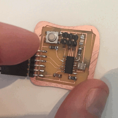
IT WORKED! The button now controls the LED. Hovever, the light is a bit weak, must be something suboptimal in the code.
Both files, zipped C file make file (Better files below.)
Click for animated picture
I found a great source for understanding the C bit manipulations going on in the example files and used that to write up an extensivly commented file which turns the LED on when the BUTTON is pressed.
Both files, zipped C file make file
Read my commented code online I used this program to turn C code into HTML
I found this colorful pinout diagram made for programming the aatiny with arduinio programs and arduino as a programmer.

I think it will be easier to read than the pin diagram in the data sheet.
I used this guide to add the attiny44 to the board options in the arduino IDE.
The LED is connected to pin 6 on the attiny package, we need to translate it into whatever the arduino software numbered it, this picture that I lifted from the high low tutorial shows us that we need to adress is as pin 7.

When testing the arduiono blink example file I got strange timing results. (128% according to a rough measurement with a stopwatch)
To solve this I selected to use the exernal 20Mhz clock and used the "burn bootloader" command in the IDE to set the fuses to use it. Worked fine! Now the timing is way better! (Please note that I still need to use the FabISP to program the echo board through the arduino environment.)

Next thing would be to explore the software_serial that the Highlow site talks about.
This is the official modern grafical user interface version of AVRdude, I have installed it and have started exploring it but have not programmed the board from it yet.
Neils minimalistic approach whith starting with as little as possible and only adding what you need feels good for preformance but is increadibly slow for me since I don't yet have the hang of what I can just drop in or what I need to write for myself. When I try googling for problems the answers I find are not on a beginner level since few people programming microcontrollers in C struggle with basic type conversion. On the other end of the spectrum is the Arduino IDE, with its preloaded libraries almost filling all available space before I even start programming. However the answers to Arduino questions online are extremly beginner firendly which makes it tempting to stick with as a microcontroller beginner. I feel there must be a middle ground where I easily can find and add packaged solutions for things like string handling, serial etc. Possibly by using a platform like Atmel Studio. I would like to know more about what different programming environments can do to help me get going as a microcontroller programmer.