Led
In Week 6 I set up the AVRdude programming toolchain and ran a make file so that I could communicate with my board but this weeks task was to make the button on the board blink a led. This I found utterly confusing, I did not understand that an inputpin could read itself and C programming looked like some outlawed sourcery. Our instructor Bas walked us through the programming and I tried to figure out what it was we where doing, we made a led blink and the we edited the code to make the button turn on the led.
We started with and added to This C file Bas explained a lot of the code but I had to do some extra reading to get a basic understanding what was going on in the code. This This Guide is for another microcontroller and it doesnt use Macros as extensively when toggling pins and ports but it provides a straight forward explanations on Programming.
The file has predifined Macros, these are funcions that simpilfy and ease readability of the code. We added threw definitions that defined Pin, Port, and Data direction to be used with the LED.

I think that makes a bitmask that selects PINA7 and sets the Port and DDR to A to be used later in the code.
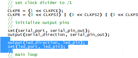
Here we set the Port and pin out with the defined Set macro and then we change the direction of DDRA with the Output macro. Here is a quote from Hackaday on inputs and outputs;
"...There are three registers for each pin that we will generally be concerned with: Data Direction Register (DDR), Port register (PORT) and Pin register (PIN). Each of these will be suffixed with a letter corresponding to which set of pins we are working with."(In my case DDR and Port are labeled A)"...Setting a bit on DDRA to 1 will make the corresponding pin an output. Setting it to zero would make it an input. Here I’ve set up an output because we are driving an LED. Outputs can be turned on or off by setting a 1 or a 0 to the PORT register respectively."
For coding we edited the while loop that waits for an input from the keyboard to run and return a message. It starts by clearing the led, waits 1 second, turns it on again, waits again one second and then repeats the sequence, leaving the led on.
This worked fine.
Button
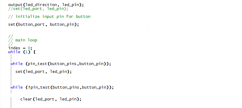
To give the button a functionality I added more Macros.
 DDR the default for direction is input(0) so that doesn't need to be set. PORTB is set to 1 to enable the pullup resistor. Or as is said on Hackaday:
"If we were using a pin as an input the PORT register would be used to enable or disable an internal pull-up resistor and the PIN register would be used to measure the logic value currently present on that pin."
Im not sure why we made the buttons_pins macro, there is no number defined for this a pin?
We edited out the initial "set" function for the led so the led would start by being turned off. The coding itself was quite simply although I had to have it spelled out for me. There is a continously running while loop with another two while loop nested inside.
The condition for that loop is a pin test that I borrowed higher up in the code, in the void get_char function is a while loop called pin test. I copied that to my while loop so that it run the "set" function that turns on the led, after that I copied the pin_test again and added a "not" sign (!) infront of the parameters to have it invert and run the "clear" function when the buttin is released
 If I measure the voltage over the internal pullup resistor of an input pin internaly it will show a 5 volt reading(The pin reads High), if I press the button the pin gets grounded and reads 0(low) I how found this hard to understand but Bas drew up a diagram for me that made things a litle clearer.
Make
Again we used This make fileprovided on the fabacademy archives, But I had to edit the top line to direct it to the .c file that I just made. I could not remember if I should include the .c ending in the name but in second attemt it worked out.
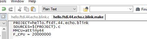
To run the make command I opened up command prompt, navigated to the folder where the file was saved. There I run make:
make -f hello.ftdi.44.echo.button.make
make -f hello.ftdi.44.echo.button.make program-usbtiny
I dont have to run the program-usbtiny-fuses as I did in week 6.
Arduino
I took a look at thisTutorial from the repository. It is rather self explanatory, a thing to note though is that Burn Bootloader function is about the same as Set Fuses command in avr dude, this should be done if you are using an external clock.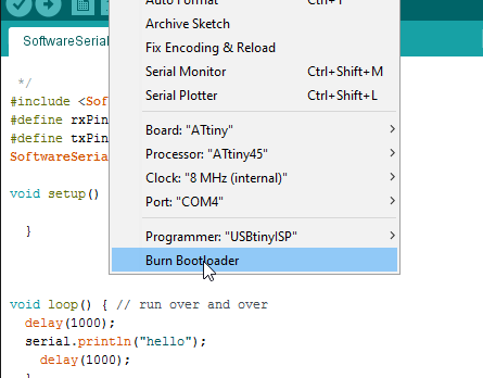 If you are programming through the fabISP you need to select USBtiny as programmer.
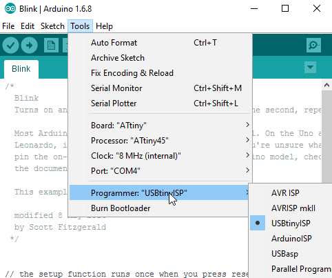
 And insted of pressing the Upload button in the IDE you need to select Upload Via Programmer.
I talk more about selecting an microcontroller in week11 wich is about inputs
The datasheet
A part of this weeks assignment was to read a locate important bits of the Datasheet for Attiny44. I did just that to some extent. The most valuable information lies in reading about wich bits on witch pin ports are by default turned on or off, to enable them as inputs or outputs.