Test cut
To get us started our instructor Bas led us through cnc joinery. As a group we decided on making a locking joint.

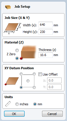
after drawing this up in Inkscape we opened VCARVE. First thing there was Job Setup, there we entered in the width, height and thickness of the stock material and importantly set the Z zero to be the bottom of the material. Then we hit ok and dragged your .pdf file made in Inkscape into Vcarve.
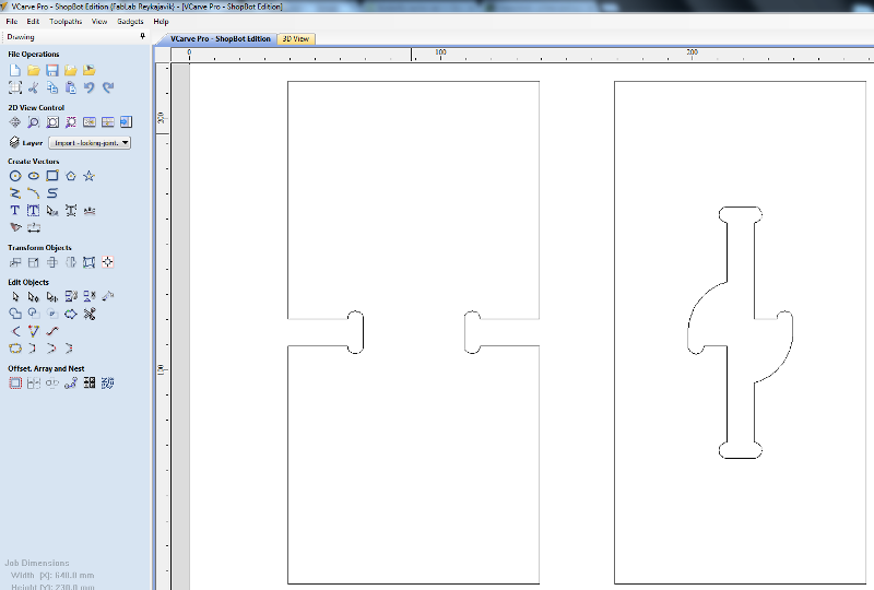
I used the Move Tool and Align to arrange the paths on the workarea. We needed to create T-bone fillets on the path where the tool would not reach otherwise due to its round shape. We needed to fix the path first by draging nodes, create a rectangle and weld it to the shape because fillets only work on 90° corners.
Now we can create a toolpath from the path. We set the cut depth to be 0.2mm deeper than the stock thickness to make sure we cut through. Start depth can be selected if we have already cut a lower surface on the stock. We selected 1/4" straight cut for our endmill and selected 2 passes. Machine vector set to Outside/Right conventional milling.
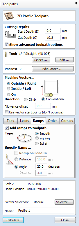
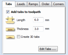
We added tabs by having the path selected and then clicking where to place them, They were set to 6mm length and 3mm height. We set the Ramp to be smooth @ 20°, Some endmills are not made to drill straight down, this makes the tool always make diagonal movement when lowering.
Around this time we pressed calculate to draw out the toolpath. Up pops a warning that the tool will cut 0.2mm through the material, we accept that.
We then drew a few circles to mark out our screw holes, we had a set diameter of 10mm and placed six of them on the canvas. With them selected we Clicked the "drill hole icon" to set the depth fo the holes.
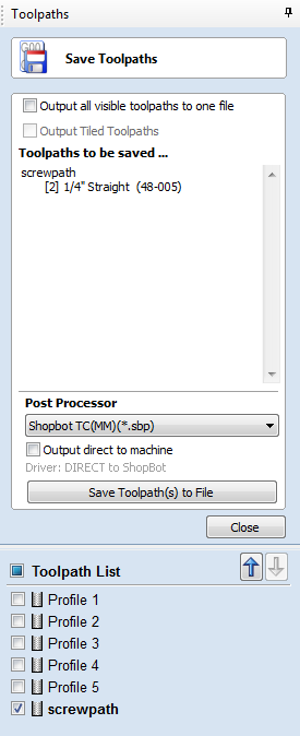
Now we clicked Save Toolpaths Icon in the Toolpath menu, we exported the paths seperately by ticking each toolpath box, We made shure the Post Processor was set to Millimeters, and then we saved toolpath. Now we moved on to the designated Shopbot CAM computer and actualy exported the paths from there and saved them to The Controler pc's desktop in a folder called Work.
The Shopbot
Moving over to the Shopbot we established an overview of its workflow. As a rule no one should operate the Shopbot alone but always have someone looking over your folder and be ready on the E-stop. After opening the window in the workshop to get some fresh air the workflow goes like this:
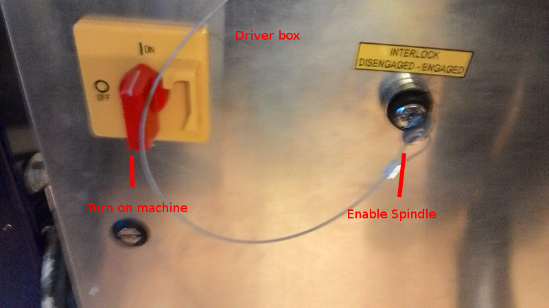
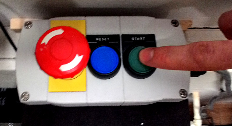
- Turn on shopbot by Turning red knob on driverbox
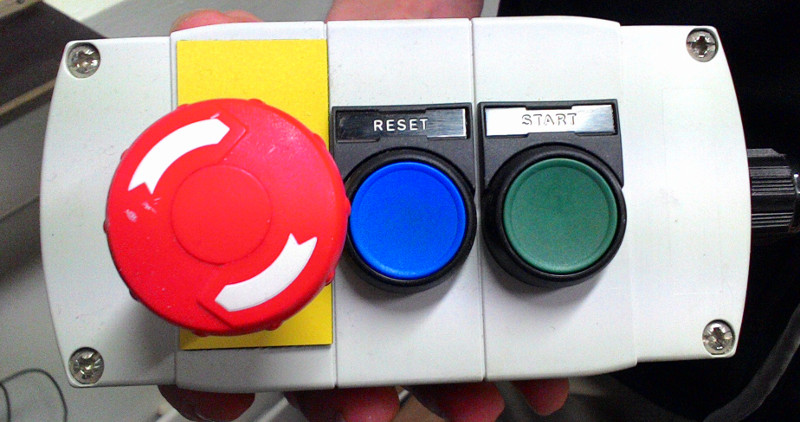
- Press Reset on the remote control, this activates drivers and cleans out their buffer
- Turn on Shopbot program on the controler PC
- Click keypad to bring up manual control and move the machine as to set XYzero, use the keyboard arrow keys for that and Page Up and Page Down for the Zaxis, make sure you understand the orientation of the Shopbot before you move it.The longer side is the width.
- Fasten stock material on wasteboard, we used spacers to bring them away from the edges of the board.
- Lower dustshoe to fit collet
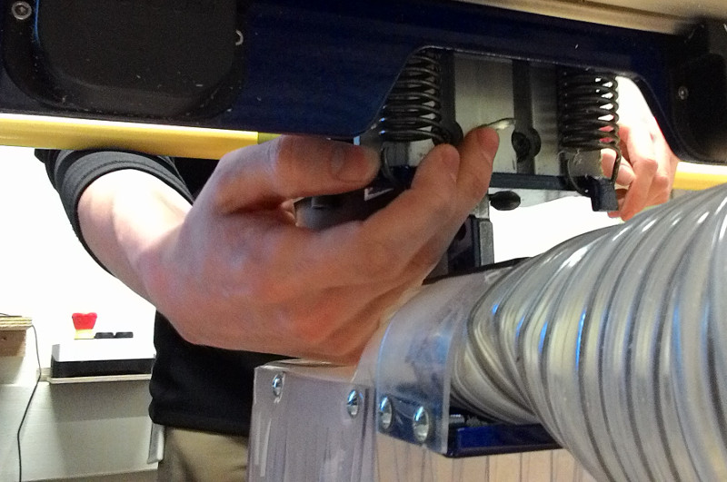
- Load Endmill into collet, make sure it only grabs the shank not the flutes, Now stick the Collet and nut onto the spindle, its good to turn the spindle to make it grab the nut, then fasten with keys.
- Higher the duskshoe again until it brushes the stock material when tool is Zeroed
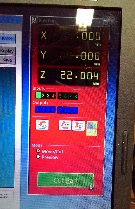
- Zero Z; Jog spindle next to the stock material, place aluminum plate under the endmill on the wasteboard, Close keyboardpad and press the Z button Icon to start calibration, the spindle makes two rounds to calibrate its Zero. (We had a new Controller PC so we had to enter setup and set the aluminum plate thickness)
- Move Machine so Center of endmill is on the XYzero corner of the stock material. We can select Fixed for smaller increments or we can manualy type in possition.
- The blue "Set Zero" button sets the machine to this Zero point.Then bring Z back up to safe height by manualy entering in the Z value.
- Turn the key on the driver box, this allows the spindle to start running
- Preheat the spindle, SPINDLE CONTROL -> RUN SPINDLE ROUTINE.This takes 12 minutes.
- Put on safety goggles
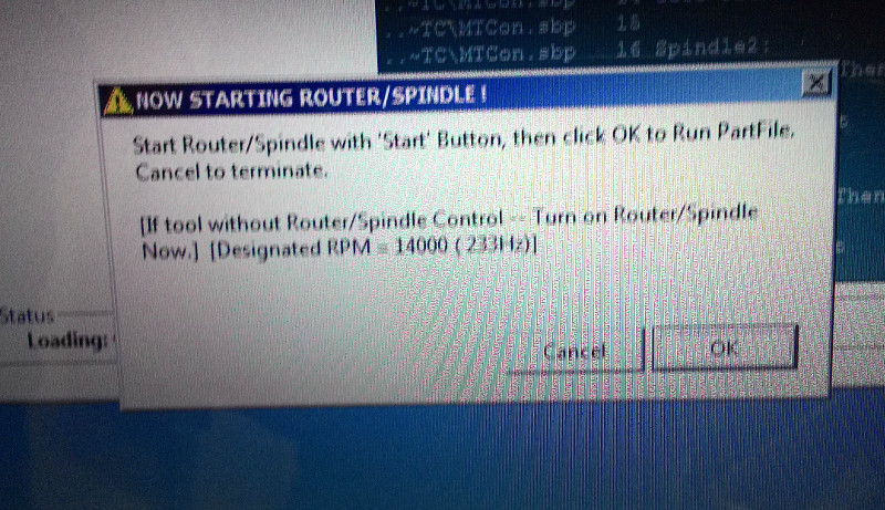
- Press start Cut on computer, select a job to be run. a warning pops up, read that warning, then press Start button on Remote control. Then click OK on the screen, use a mouse not the trackpad
My project
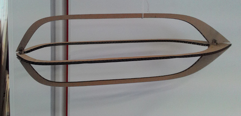
After a bit of wondering I decided to make a Zeppelin, I've had this idea of a Zeppelin lampshade for about a decade or so. I modeled a Zeppelin in Fusion 360, The process was pretty freestyle, just having two disks that had pressfit connectors for the Beams. I made the pressfit slots as arrays so If I changed one of them they all changed. the length was about 130cm and I set the Material thickness to 1cm. Then I did a prototype in the LazerCutter, I figured that I could scale the whole model at once to 40% of its size I would get 4mm material thickness that would fit a Pressfit for MDF. I scaled the model but when it came to cutting I changed from MDF to cardboard, I didnt bother scaling the model to the cardboard thickness I knew I could just cram it together. So here it is, without rudders and only with 4 supports.
I liked the porportions of it so I headed back to Fusion 360, Now I needed to parametricly change the pressfit of each piece to fit the OBS material wich I measured as 11,9cm, I didnt want to scale the whole material because it would be to long. It took my a little while to figure out how to place the components after scaling them.
To export drawings in fusion I right click the component and selected "New Drawing", this allowed me to place the part on a technical drawing, I could not set a custom size for the document size so I needed to scale the Zeppelin Beams 2:1 to fit them on the canvas. This meant that when I exported the pdf, I needed to open it again in Inscape to scale it again to 200% and then re-export it as pdf to be imported to Vcarve.
I luckily seperated the toolpaths that is exported from Vcarve so that I could start cutting the small connecting disks to test the print. I did just that and found out that I had forgotten to widen the fit on just that piece. I went back to Fusion 360, changed it parametricly and exported it seperatly and added them again to my Vcarve file. This time things went good as expected
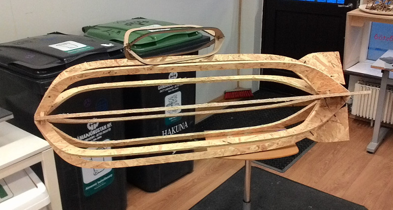
With the rudders added it looked as much like a bomb as it looked like the Hinderburg, did I make the Hinderbomb?
The pressfit fitted quite snuggly but there was still a litle play in the beams, they only overlap eachother by 1cm on each side and with the Bone Fillets I guess that allows for some flexibility.