design and build a wired and/or wireless network connecting at least two processors
Idea
I will make a network between my CNC controller and a board which handles jogging inputs. It will make it possible to control the CNC directly with a joystick without being connected to a PC.
Manual jogging: Moving a machine with direct move by move commands instead of having it follow a preprogrammed path.
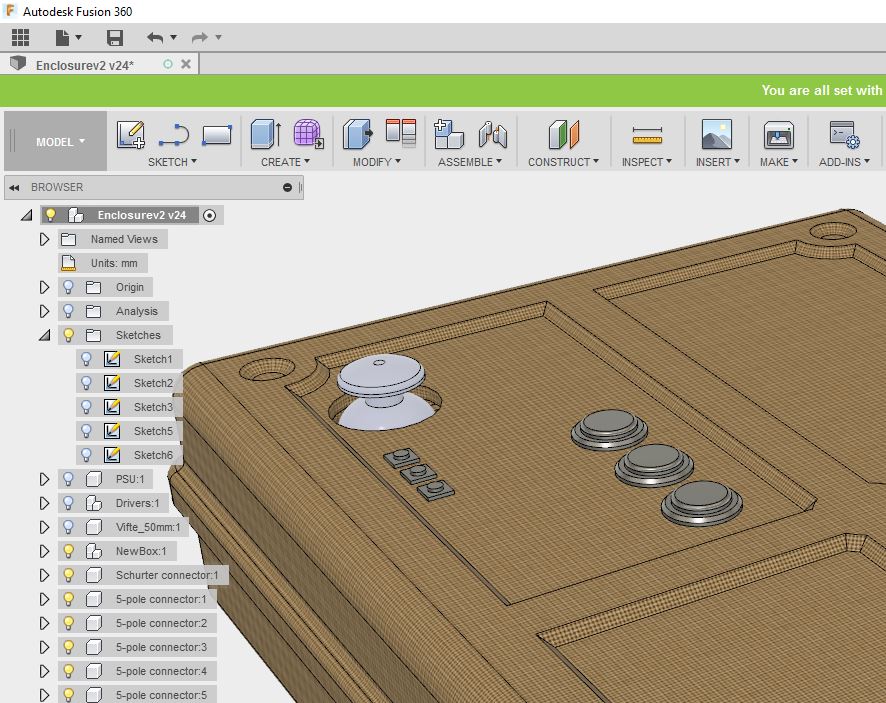
My control box, made in composites week14 with an added visualisation of how my installed manual jogging controller might look when it is done.
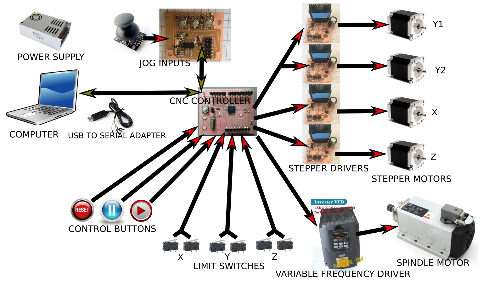
Here is a block diagram of all the necessary communications. Green arrows = back and forth communcition, red = one way.
Detail view of the back and forth communcications.
I would like to keep my new components compatible with the existing solutions for open source CNC control. That way I can easily keep it up to date with the latest developments and it is likely to be more attractive for other people to make and use my components as well.
However this gives me some challanges. The serial communication I want to use has no standard support for "multi-drop" or more than two units talking on the same line.
Luckily there are workarounds!
Avoiding crosstalk
One at a time please...
My intention is not to stream G-code while jogging, that should never happen. So a solution that allows either the Computer or the Jog Inputs talk to the controller one at a time is fine. What I want to avoid is catastrophic consequences if they accidentaly try to talk at the same time.
Sharing the serial line, options
If I just tie the communication lines together and they both talk at the same time they will act like a short circuit and potentially get damaged. One potential dirty fix is to just put resistors in series to limit the short circut current to safe levels. That can actually work but it might reduce the signal quality and two sending at once will make for garbled communication.
Another workaround would be to make the signal line normally high with a pull up resistor and and sink current through a diode at each transmission point. However it sounds like more work for less gain than to deal with it in software.
Man in the middle concept
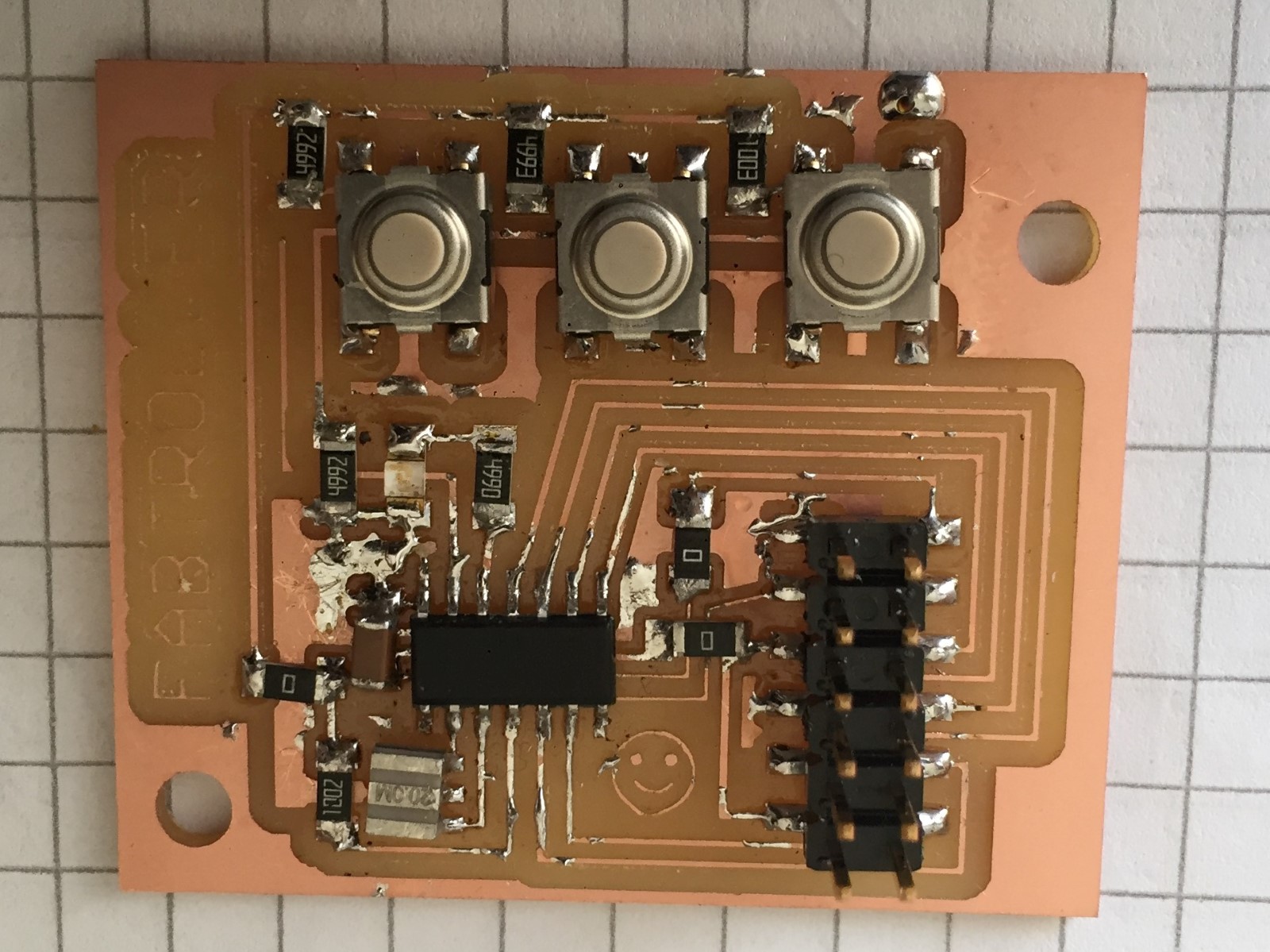
My "fabtroller" which I made during the input week can be used as a "man in the middle". Under normal operation it will forward the data stream from the computer to the controller. But then the fabtroller wants to send jog-commands it will send those instead. Blocking any attempts from the computer to issue commands at the same time.
The status feed back from the controller could stay connected in paralell all the time since it never needs to be interupted.
I think this would work fine, possibly too fine, I might accidentaly interupt communcations from the computer to my controller by touching the joystick.
Adding a proper switch for choosing between the "computer control" and "manual jogging" modes will be safest.
Conclusion
A physical switch will simplify it even further by toggling the transmission line between the inputs. This is what I will do.
Alternative path, A network of smart stepper driver modules - Discontinued
I first started planning my motor control for my final project CNC machine during output devide week10. I then had a different communication strategy in mind. I planned and begun design of a stepper motor control board that would have both physical and digital inputs. The goal was to make an extremly modular, smart, fabricateable stepper motor driver board that could be networked and used instead of the Gestal Nodes used in the MTM modules.
I studied the provided lecture examples for the networking week ahead of time to make the boards be able to communicate via I2C. (An easy to implement networking standard that allows for adressing and multi drop.) I also gave each board an FTDI- and a ISP-header. This way any one of the boards could easily be turned into the network master to recieve and relay instructions from a computer.
The three buttons would give the user the option to control each motor directly without having to open programs on a computer. I also entertained ideas that I could add header pins to make it possible to connect switches in paralell to the buttons, allowing more complex machine behaviours to easily be tested and then built.
I eventually decided to focus more on making a functional CNC milling machine and less on making a super-modular system for machine building. My main reasons for deciding so was that a functioning CNC milling machine feels more finished as a final project.
I absolutely want to revisit these plans later.
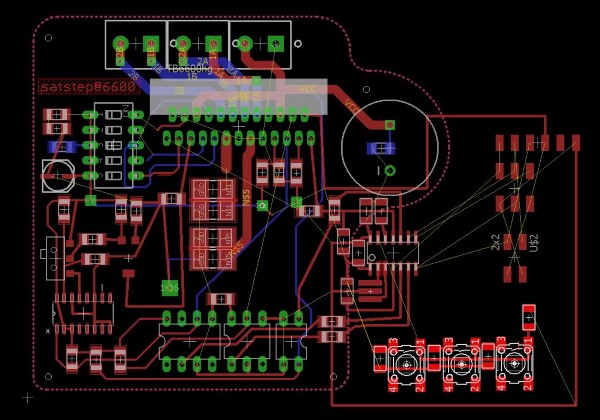
Here is my (paused) All-In-One networkable stepper driver module that I ended up breaking into two boards for the input and output weeks. They were intended to communicate via I2C.
The CNC control firmware I want to use, GRBL, is made to run on a stock Arduino UNO microcontroller board.
Since this is Fab Academy I wanted to try to make one myself, especially since there apparenly are several DIY versions already designed. Satshakit seemed to be a good starting point since I knew from the class mailing list that the board can be cut on the lab CNC and other labs have been making them this year.
Therefore concider all content on this page to be licensed Attribution-NonCommercial-ShareAlike 4.0 International (CC BY-NC-SA 4.0).
Hopefully I can get the satshakit team to remove/clarify the non-commercial requirement. If so I will upload my work to fellesverkstedet/fabricatable-machines, look for it there if you need a more free license.
Missing 16Mhz crystal
The BOM for the satshakit board uses a 16 Mhz crystal and two 22pF capacitors that are non-standard fab academy student kit components. This means that we didn't have them in the lab.
I checked the lokal stores and they will stock it later this year, but not currently.
Will 20Mhz do?
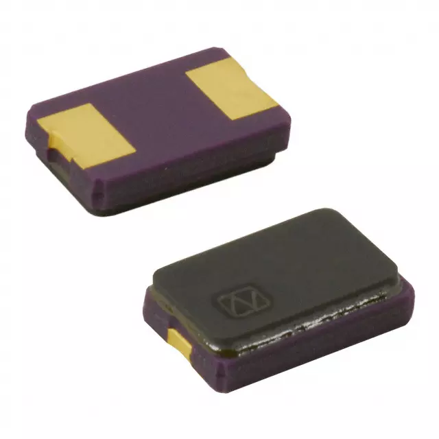
Instead of the 16Mhz the student kits have 20 Mhz crystals(datasheet) and matching 10 pF capacitors (choosing capacitors 12) which would actually make the ATmega328p microcontroller (datasheet) run 25% faster.
I googled around and it seems that with a 20Mhz crystal it should still work both as a Arduino clone (Source 12) and for GRBL (Source 1) provided that I compile the code for 20 Mhz and double check that all timings are correct.
I couldn't find a straight up guide for how to make this work so I have to figure it out as I go. If I can't, then I'll order a 16Mhz crystal.
UPDATE: I ended up ordering a 16 Mhz crystal and two 27pF capacitors and replacing them on the card.
Fabbing the board
I cloned the satshakit repo and started looking at the board files in Eagle (Circuit board design program). I noted that some small misalignments were causing a few tight spots to go below my mill diameter of 0.4mm. I forked the repository, realigned the traces, and and made a pull request to the team managing the satshakit board. Follow the pull request here.
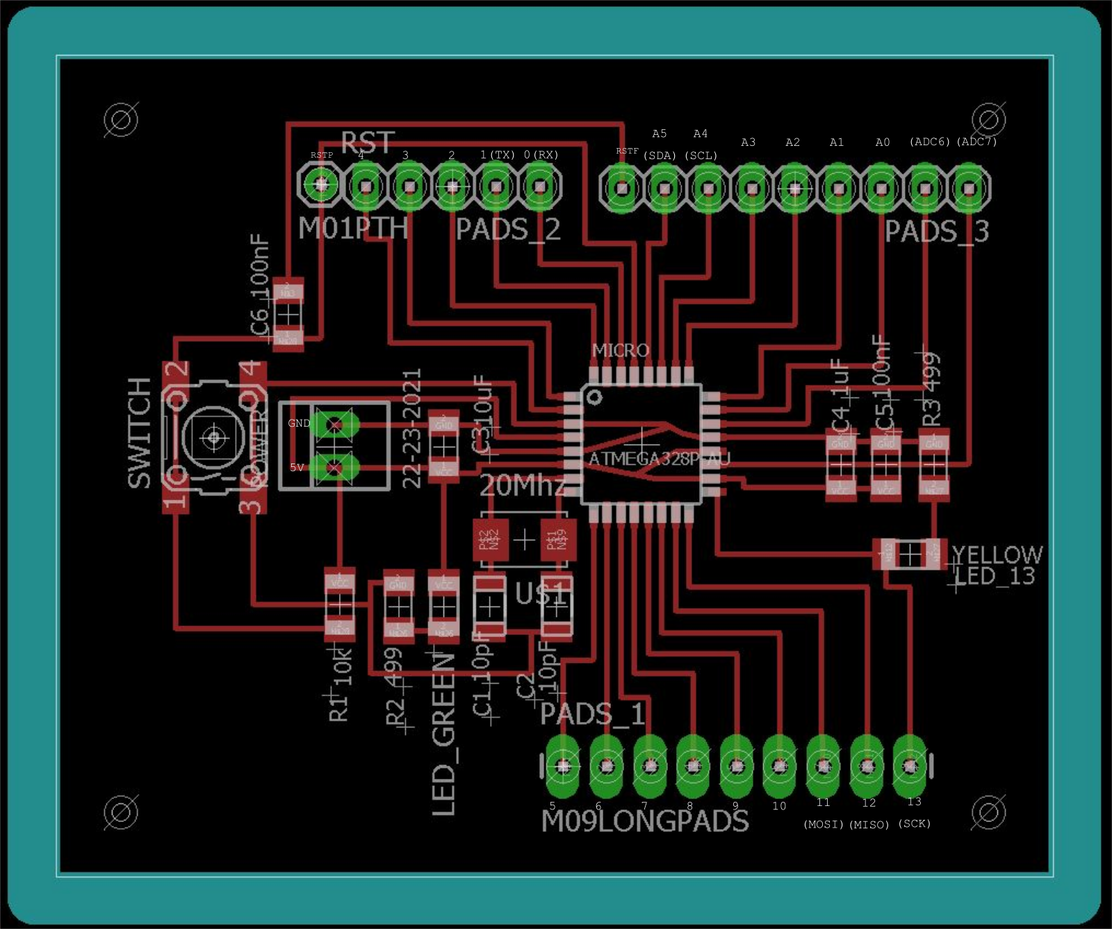
I exchanged the 16Mhz crystal and capacitors to my 20 Mhz version and could not help rearanging the other resistors and capacitors as well.
To generate toolpaths (CAM) to mill the board I used a plugin for Eagle called PCB-gcode. It generates GCode that is directly compatible with the CNC machines in the lab.
I really appreciate to be able to CAM directly in Eagle since it makes it really fast to do updates if you realise something is wrong when you stand by the machine. And it is also better at doing contour milling and drilling than Mods.
Trick for cutout milling:
Select "line" (not "Route")
Set it to be slightly wider than your cutout milling bit
Set it to layer "Milling"
Draw where you want to mill the outline.
In the PCB-Gcode plugin, first pane, under "Board" check "Generate milling" and set it to slightly deepther than your board is thick.
However sometimes it bugs when trying to generate multiple isolation milling passes, single pass always works.
If you get a bug, try this:
First delete any extra "ground plane polygons" that is left behind by the plugin. (They are red shapes which become red dotted outlines when you start deleting them.)
Then run it again, same setting but with "single pass" checked. This should work.
Try your multi pass settings again.
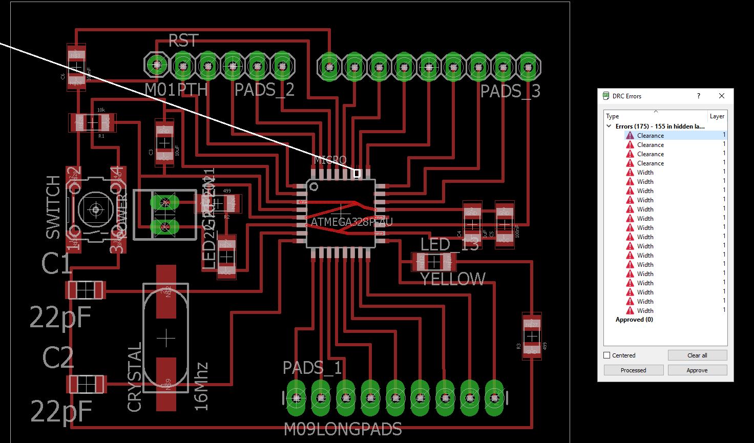
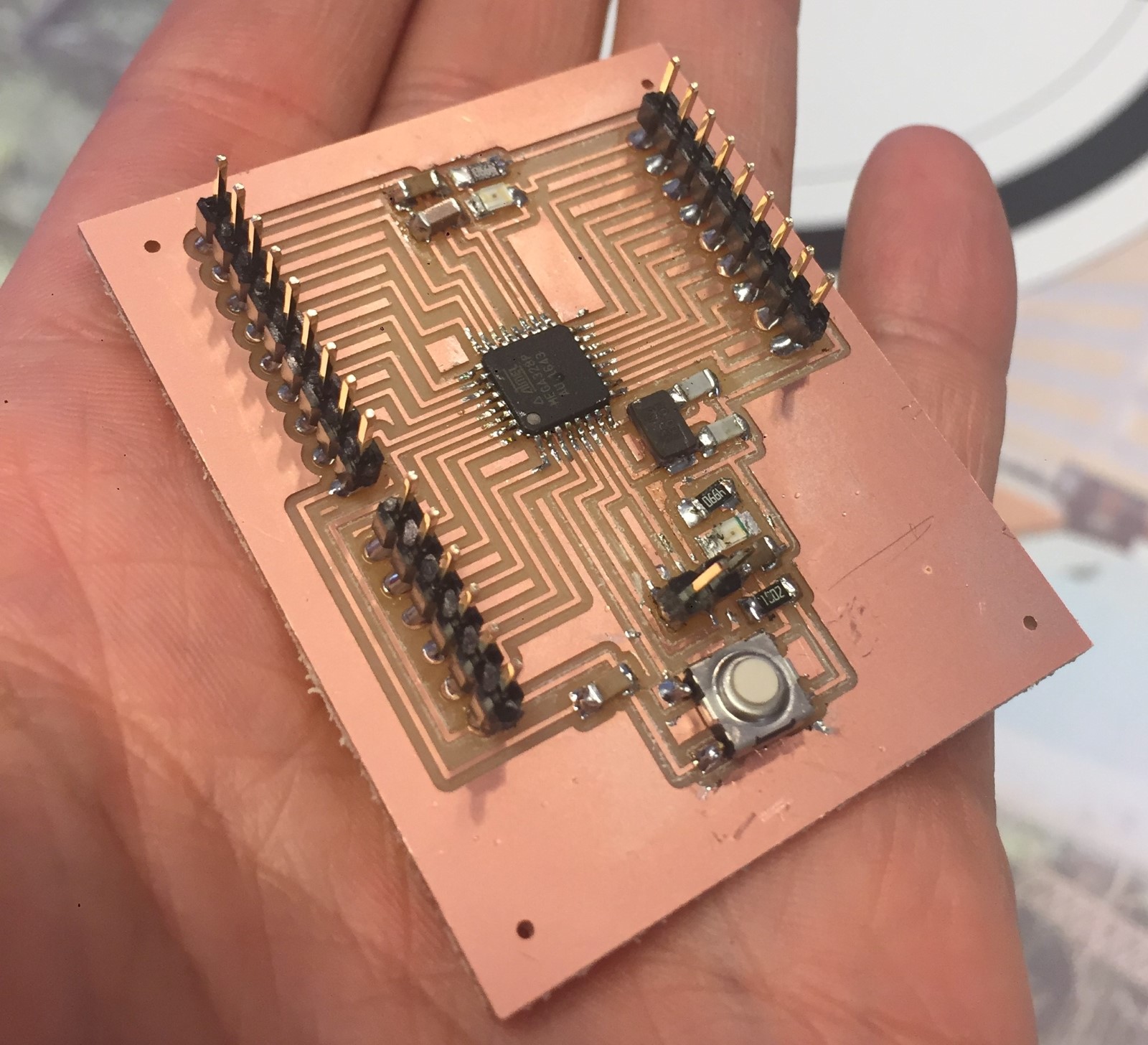
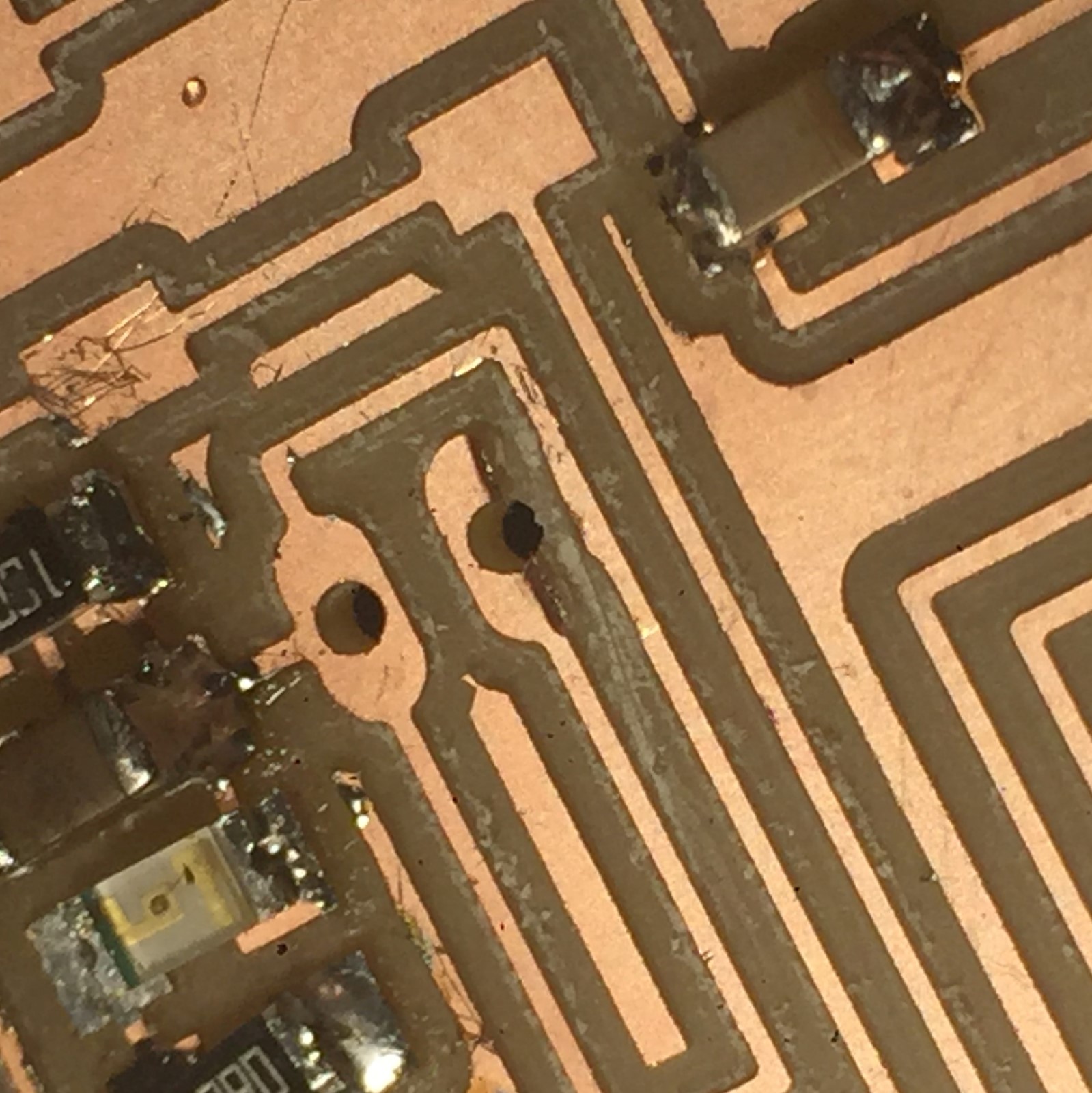
When stuffing the board I noticed I had a milling error between a pad and a trace, it turned out I had been sloppy and didn't run the Design Rule Checker (DRC) in Eagle a last time. I fixed it with a knife and updated the board files.
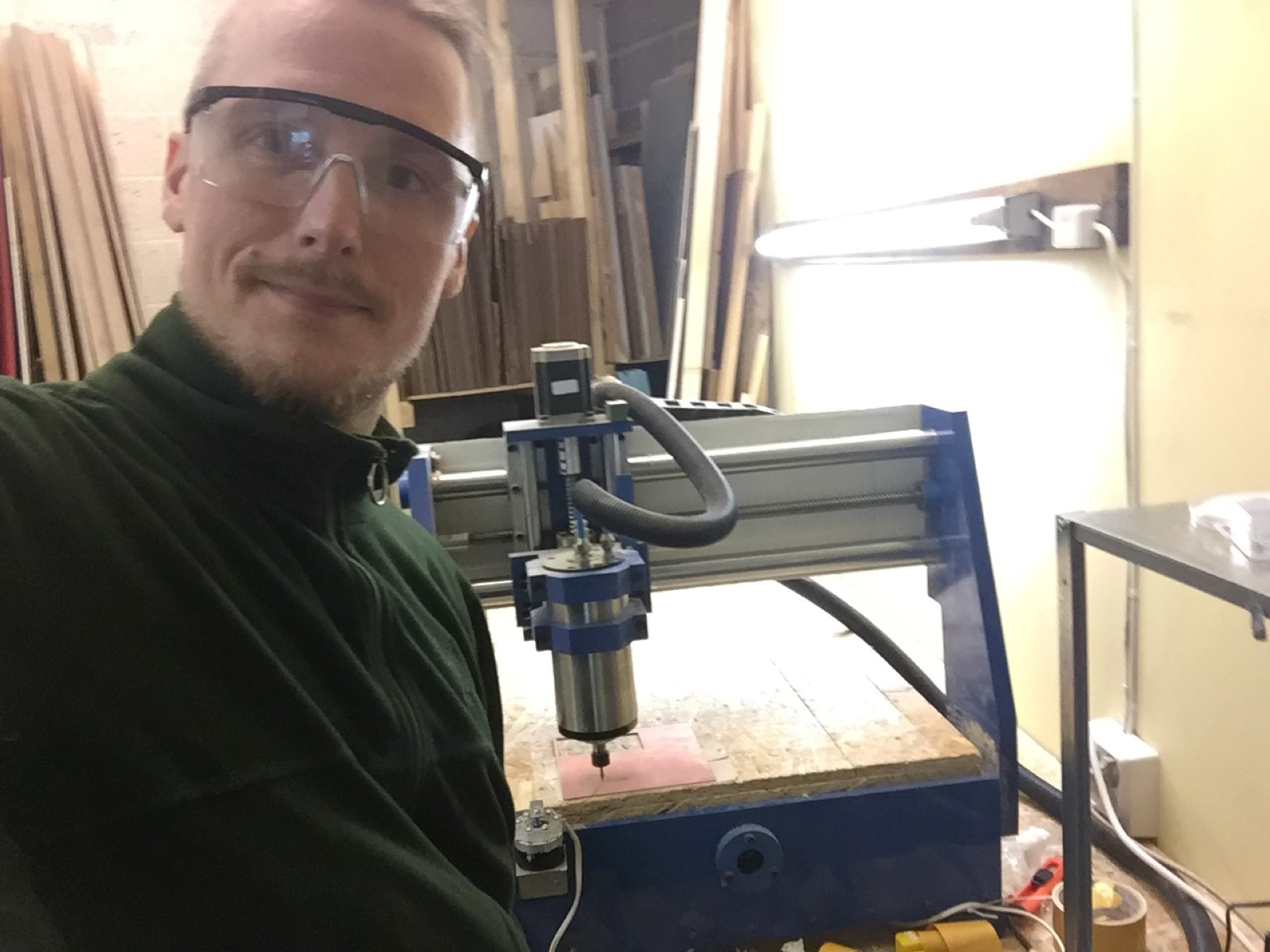
Me milling with a new small (Chinese) milling machine, worked great and and was (alomst) silent!
Programming the board
Since I wanted my board to run like an Arduino I tried to program it through the IED.
I had to try quite a few combinatons of bootloader and boards.txt configurations before getting it to work.
Finally I got it to work with the 8Mhz internal clock using a modified version of Niels lecture notes from week8. They were no longer working as is due to updates in the Arduino IDE.
On windows systems the boards.txt file is located in your program files...Arduino\hardware\arduino\avr folder which means that you might need admin rights to alter it.
NOTE! I might have messed up the boards.txt so that you can't burn the bootloader, if that is the case try starting with Niels boards.txt instead and add lines from mine as needed.
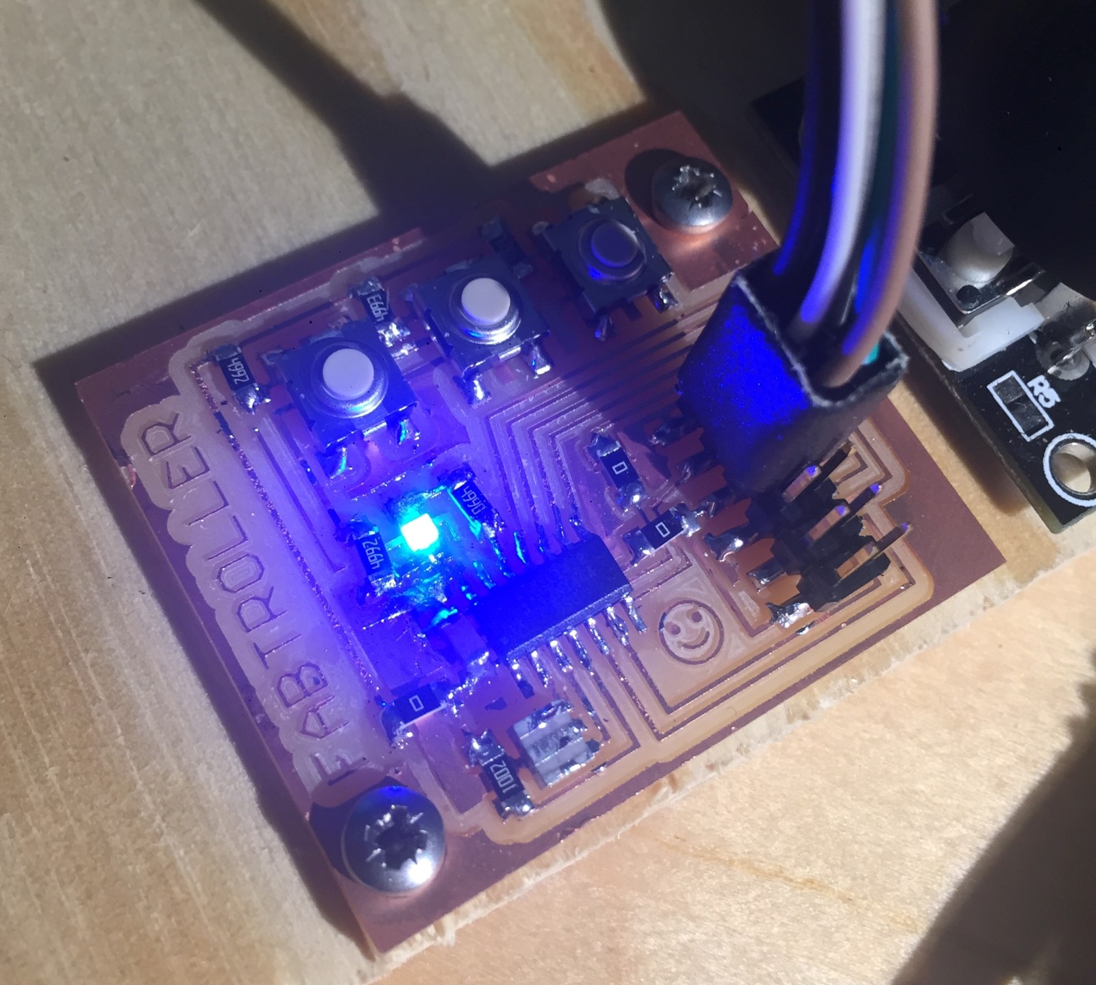
Test Results I can program the board and blink the LED using the arduino blink example, timing seems normal.
Now you can program it via the Arduino IDE, but you still need to use a ISP.
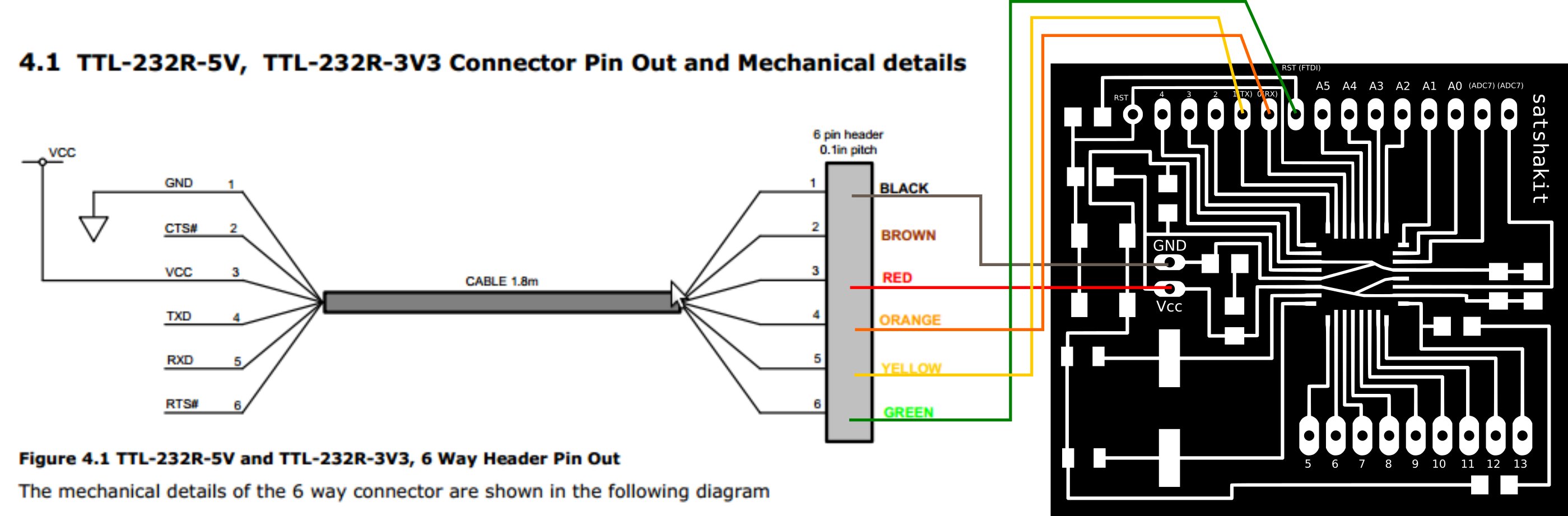
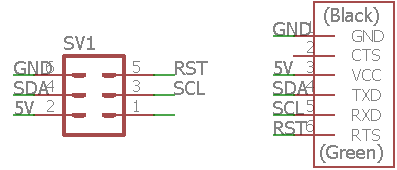
Connecting the boards
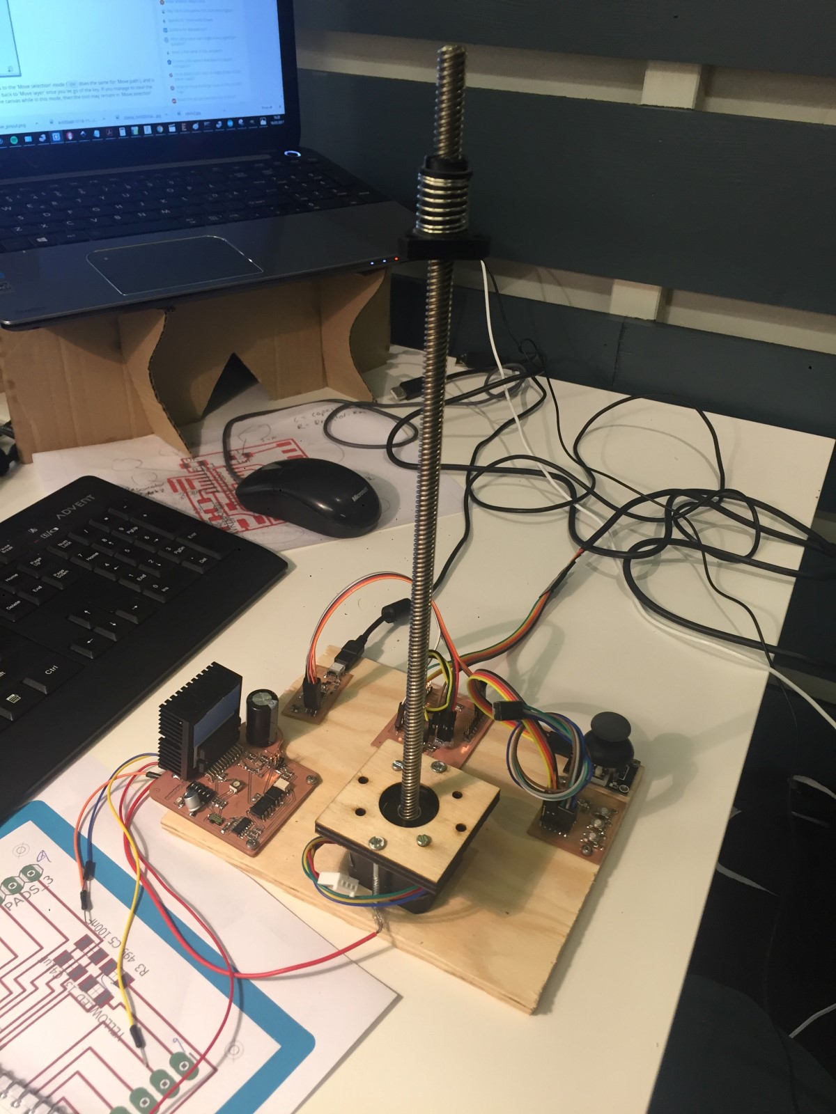
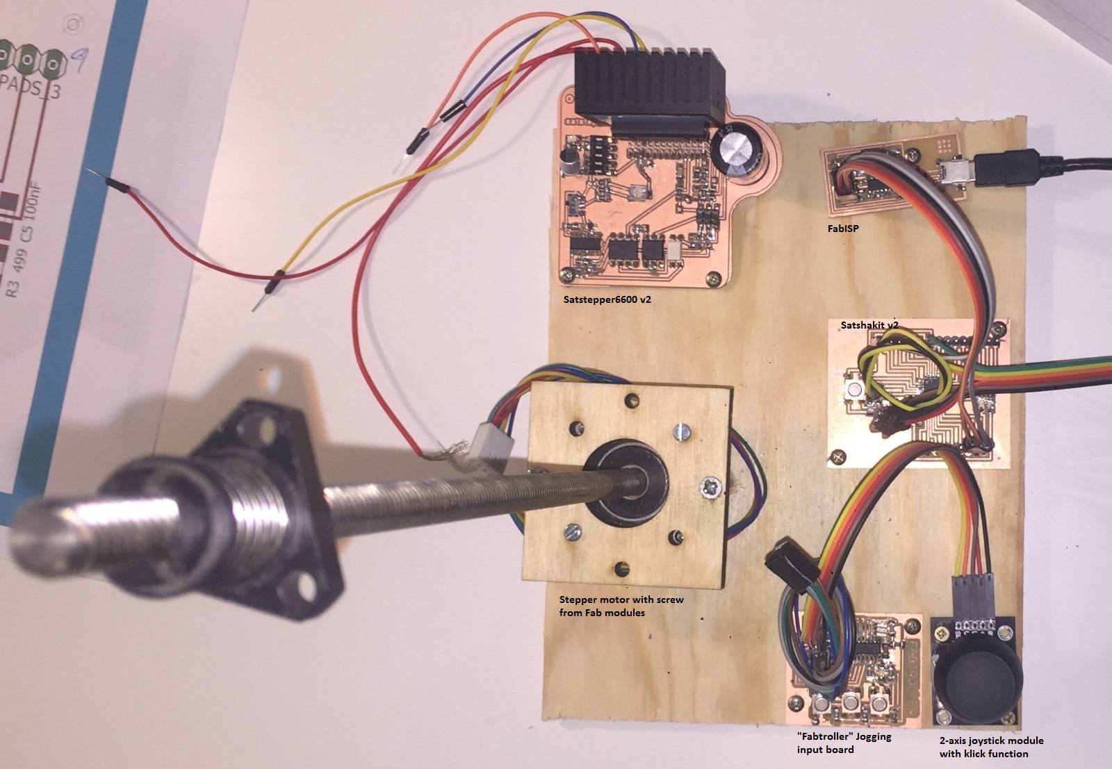
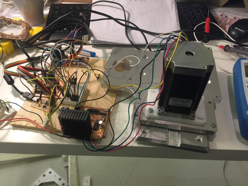
I made a small prototype board to screw everything to so I could keep everything connected and still move it around.
Broken Board :(
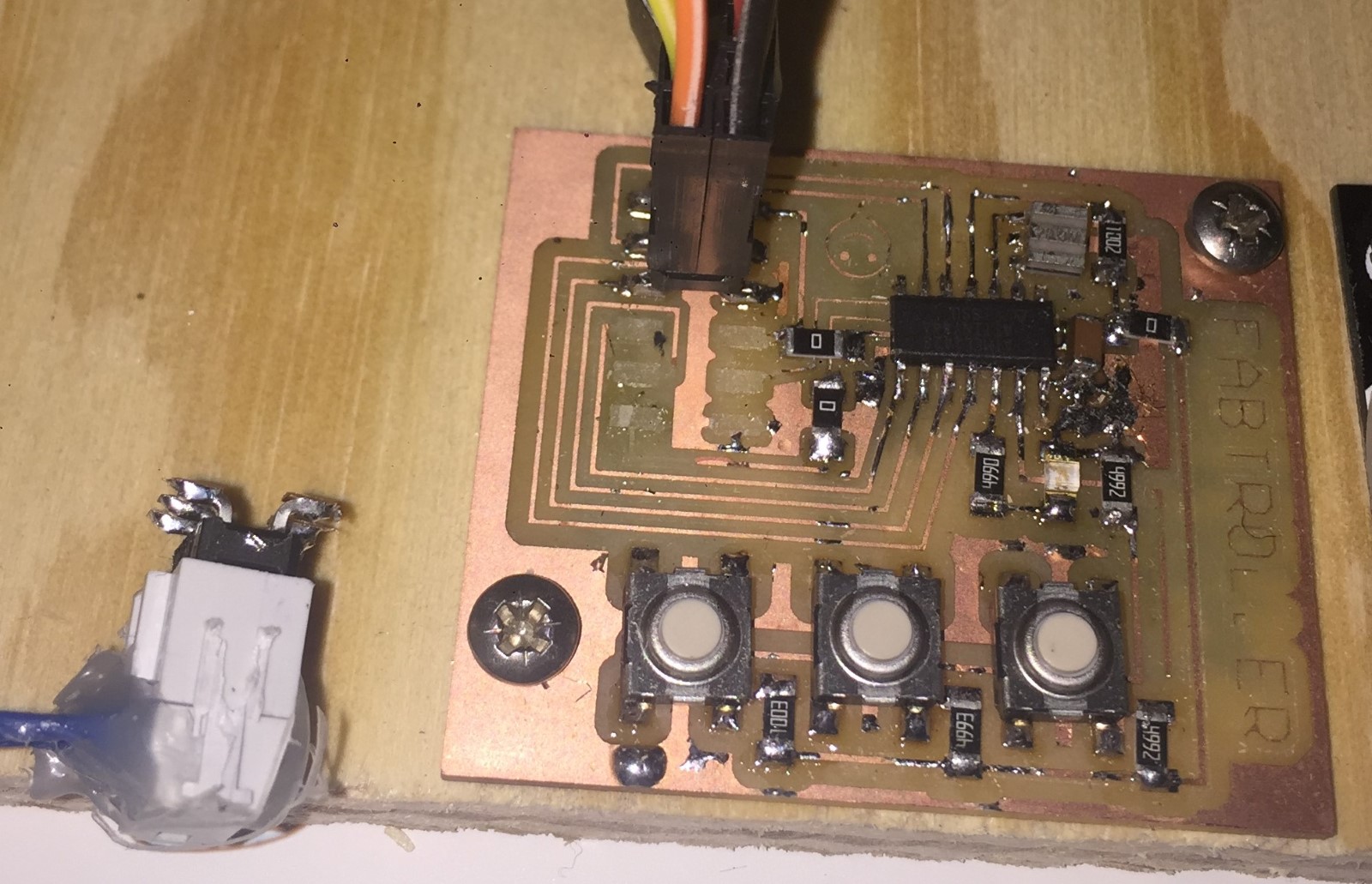
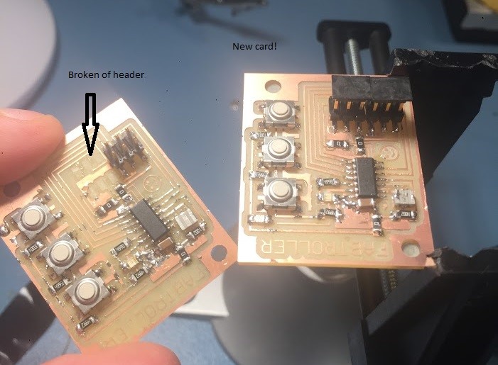
I accidentaly broke my fabtroller when I was connecting them up for testing. It happende partially because I had put the 6 pin headers too close, so if will mill a new one then I should move them apart first. I might fix this one for now with some solder, however that will not last forever.
Made a new board!
Using the same CAM files but the new, smaller milling machine I made a new copy of the same card that broke. It was suprisingly fast, I am very happy to see how much I have improved! I milled and stuffed the card in less than 1,5h including cleaning the workshop.
Fixed bug in board
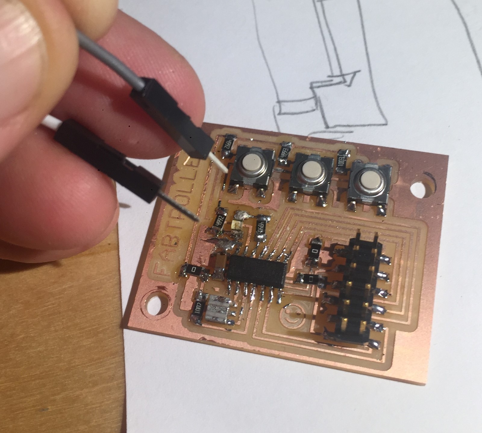
When testing the board I didn't get the Blink example working, so to test the LED I applied 5V from the ISP header directly over the LED and resistor using breadboard cables. I got the LED working, but it was on the wrong way! Apparently I had written myself bad instructions. Time to desolder... I used my private soldering iron which turned out to be much harder to use than the ones in the lab! The solder would either not melt or become crazy hot, and when I removed the tip it quickly flashed into a dull gray indicating too little heat.
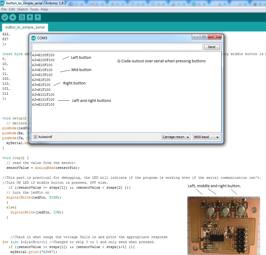
I used this parsing serial guide and wrote my own serial string interpreter. I will later run GRBL on this controller card instead of this code. So for now I am "simulating" a dummed down GRBL. I'll have to adjust timings etc to my acceleration when I have built my final project CNC machine.
I used the information about which button was being pressed to control the stepper driver that I built in week10.


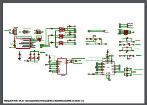 Schematic of (moth balled) all in one card.


