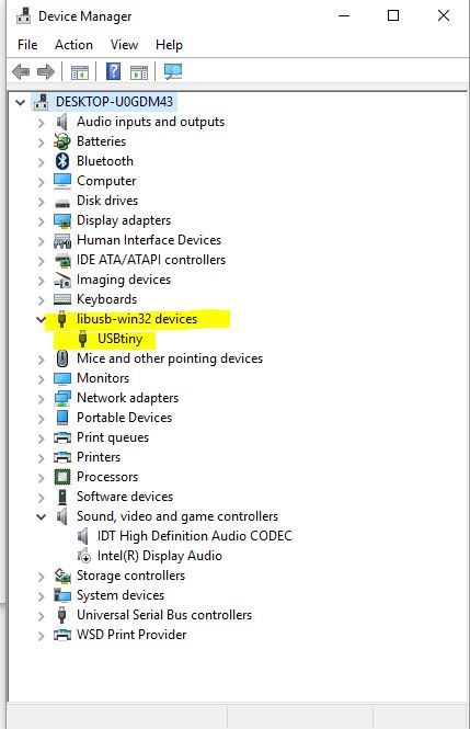
If it shows up like something else, then you need to download new drivers.
Detatch the USB from the PC when you have verified it to cut power before you connect your new board.
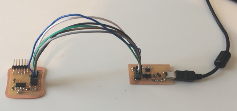
You need to have the 0-ohm jumper still soldered on your FabISP to power the board from your USB socket.
Connect the USB to the computer after all other connections are made.
Skip ahead to point 4 if you have already programmed boards with arduino on this computer.
Open the preferences dialog in the Arduino software.
Find the “Additional Boards Manager URLs” field near the bottom of the dialog.
Paste the following URL into the field (use a comma to separate it from any URLs you’ve already added):
https://raw.githubusercontent.com/damellis/attiny/ide-1.6.x-boards-manager/package_damellis_attiny_index.json
Click the OK button to save your updated preferences.
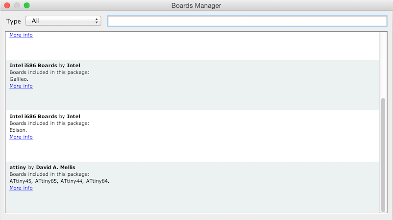
Open the boards manager in the “Tools > Board” menu and acroll to the bottom of the list where you should see an entry for “ATtiny”.
Click on it and install it.
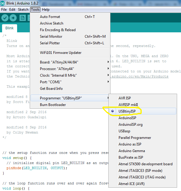
In the Arduino interface open the Tools->Boards menu and select the correct Attiny
Also select the correct Processor under Tools->Processor
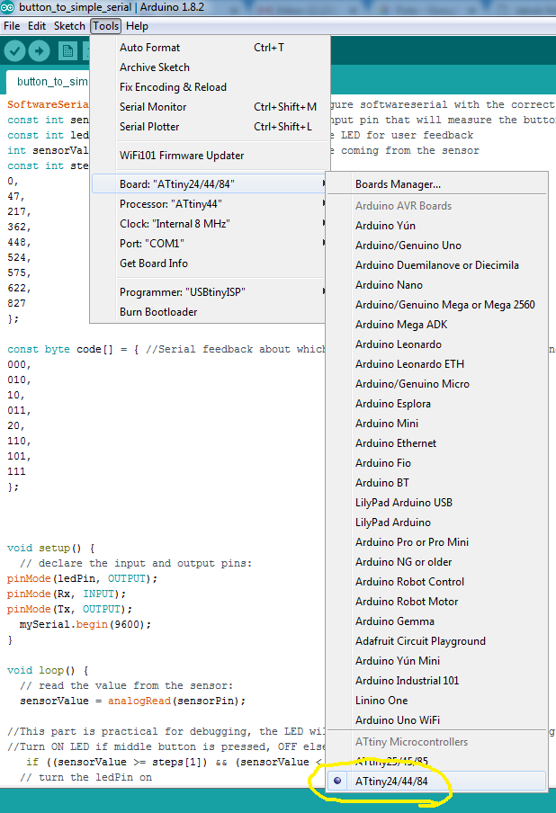
Select the programmer that you will use. Most likely you are using a FabISP and that means you should select "USBtinyISP"
We need to tell the attiny which clock to use. You only need to do this the first time you are programming a board or if you want to change the clock speed.
Skip ahead to 7 if you already have programmed the appropriate clock speed
For the Attiny44 we can use the 8Mhz internal clock to start with. However there is a slight risk that its timing is off so that serial communication will not work. That can then be compensated for in several ways, some requiring the use of a occiloscope.
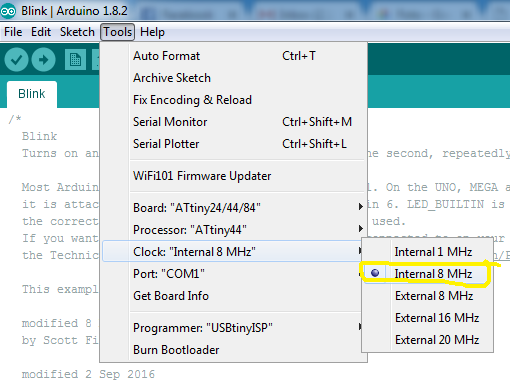
Which the clock selected press Tools-> Burn bootloader. This sets the fuse bits in the attiny to instruct it to use the clock source you selected. NOTE: For the attiny44 the "Burn Bootloader" command does not burn a bootloader, but with some larger AVR microprocessors it will.
Time to make a test program for your board! Open the Blink example from File->Examples->01.Basics->Blink
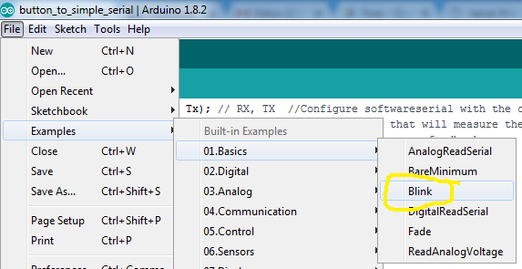
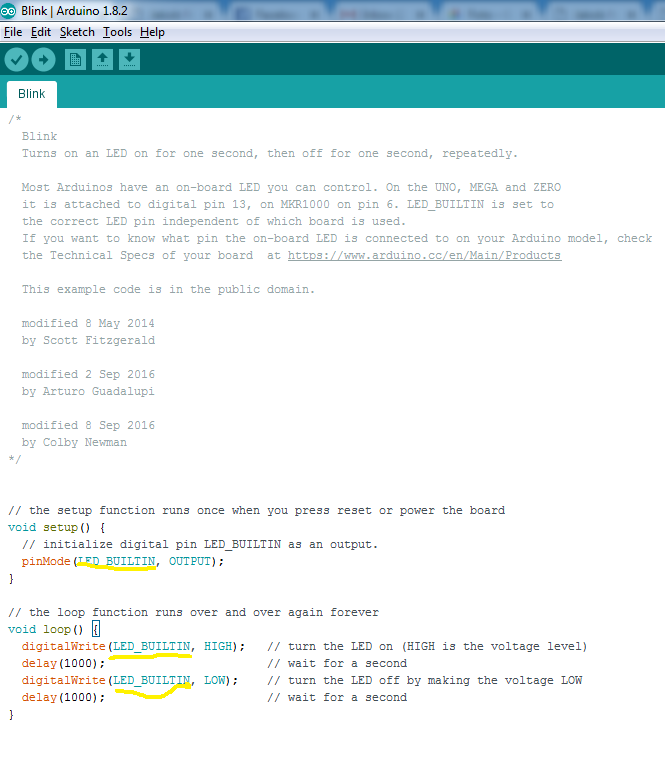
Figure out which corresponding arduino pin you have a LED connected to using your schematic and this handy conversion chart:

In my case it is Attiny44 pin 12 = Arduino pin 1. Replace the text LEDBUILTIN with the arduino pin nr, in my case 1.
Note: I have sometimes gotten a "avrdude: verification error; content mismatch" error but after disconnecting the USB cable and trying again it has gone away.