WEEK 7
COMPUTER CONTROLLED MACHINING
ASSIGNMENT
- Make something big (on a CNC machine).
Preperation
This week we have to design something big using 2D or 3D design softwars and process it using CNC Machine, here in our lab the CNC machine available is Shopbot PRS Alpha. I have identified Rhinoceros software to design the 2D designs, surfed many sites and finally decided to make a stand for Roland Vinylcutter in our Lab. These are the sites having good collection of designs.
ShopBot PRSalpha CNC
Before starting the design will know about the machine its operation,specifications,workflow are important, we have to design by considering all these things. ShopBot PRSalpha CNC is a is a low cost, computer numerically controlled router (CNC Router)
ShopBot. ShopBot can perform precision, large format, cutting, drilling, machining, and shaping in many materials and is controlled by a standard personal computer. The shopBot we are using is PRSAlpha 96X48 ,96X48 is its Gantry size i.e 8X4 foots.ShopBot PRS Alpha 96X48
The ShopBot PRSalpha delivers rapid transit speeds of 1800 inches per minute and cutting speeds of up to 600 inches per minute. Easy to configure and re-configure, learn and use, the PRSalpha CNC delivers affordable, full-production performance in digital fabrication of wood, plastic, foam and other materials. View More
Safety Precautions
Shopbot is one of the dangerous machines in Fab lab and we must take some safety precautions while working with it, here I am noting some safety precautions that i got from one documentation.
You SHALL
- You SHALL wear ear protection while working
- You SHALL wear closed-toe shoes at all times.
- You SHALL wear eye protection when working with tools and processes that involve wood chips or sawdust
- You SHALL secure badge and any loose items that might get caught in moving machinery.
- You SHALL make small cuts at slow speed otherwise you will risk breaking the cutting tool, and ruining your material
- You SHALLalways be ready to react in case an operation fails
- You SHALL make sure the spindle collet and cover nut are properly secured and not over-tightened.
- You SHALL always use a sacrificial layer under the material you are cutting, so as not to cut into the table below
- You SHALL ensure the End Mill is fastened securely inside the spindle collet, before starting your operation
- ou SHALL use your sense of sight and sound to keep yourself aware of the operational conditions of the ShopBot for safe use
You SHALL NOT
- You SHALL NOT leave a machine unattended while in operation
- You SHALL NOT touch materials and chips being cut since they can be hot
- You SHALL NOT wear or have any loose objects on your body while operating this machine
- You SHALL NOT work alone while in the SpaceShop
Machine Operation
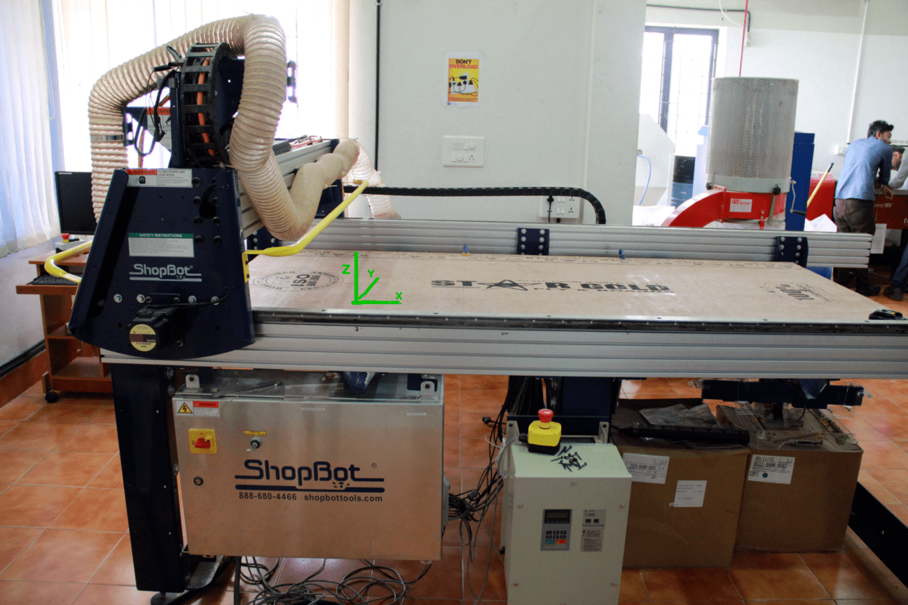
Inorder to Start working with shopbot, first we should know about the parts of the machine and operation of each. ShopBot PRS alpha 96X48 in our lab is shown below. The X,Y and Z axes are marked in the picture, the bed is having the dimension of 96X48 inches in X and Y directions and Z is 6 inches. Next we will go through each parts of the machine.
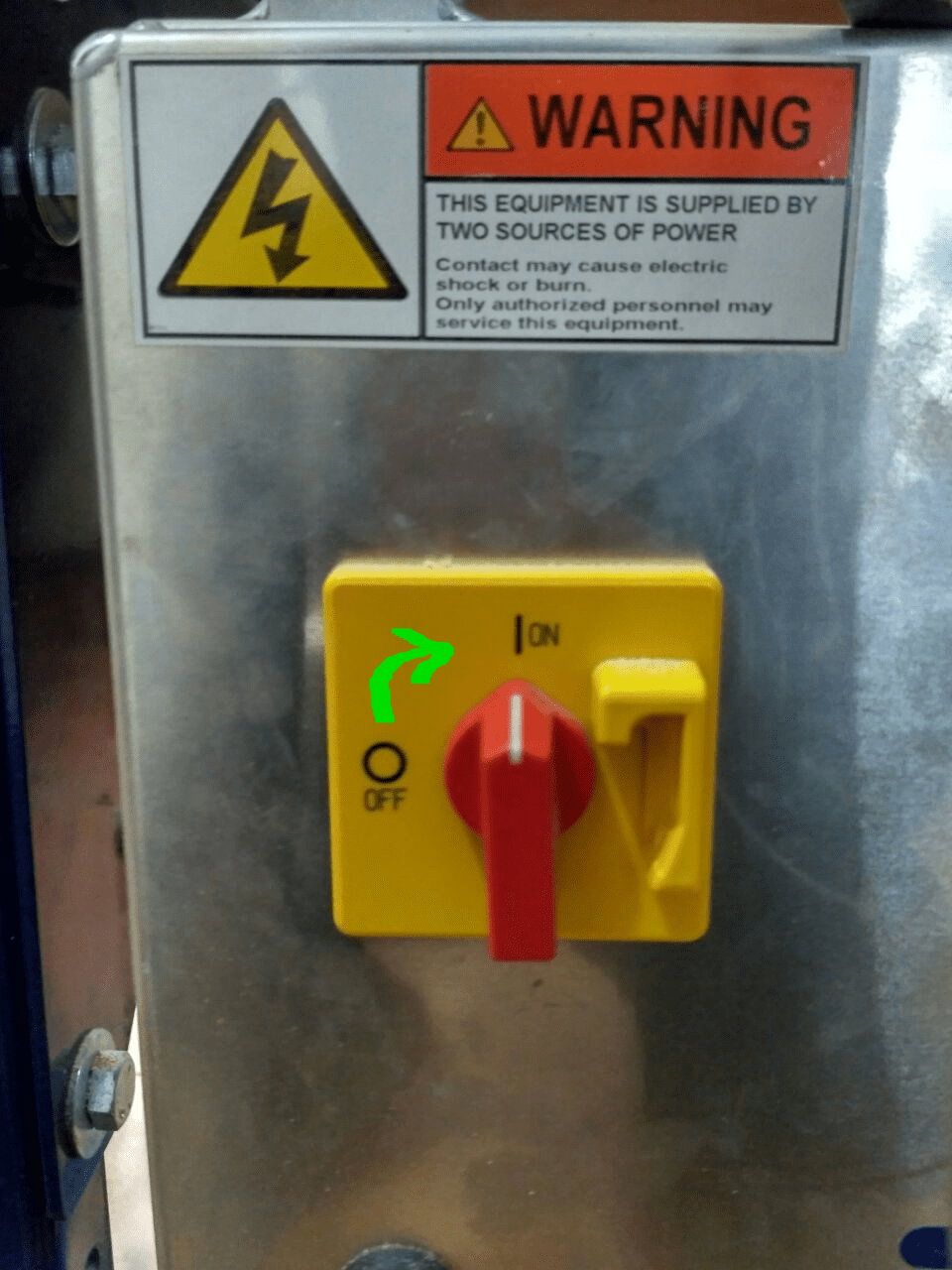
Machine ON/OFF switch
The ON/OFF switch is in the right side of the machine near to the control box. This can be turned ON/OFF by simply turning the red colored knob from ON to OFF position as
shown below. The machine is powered from single phase supply.
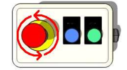
ESTOP Switch
ESTOP switch is Emergency STOP switches are used for stopping the work during emergencies there are two emergency stop switches will be there, One is ESTOP box which contains two
additional switches one for Starting the spindle and the other for Reset. Ensure these ESTOP switches are in the OFF position position by rotating the RED STOP button on the DONGLE COUNTER CLOCKWISE
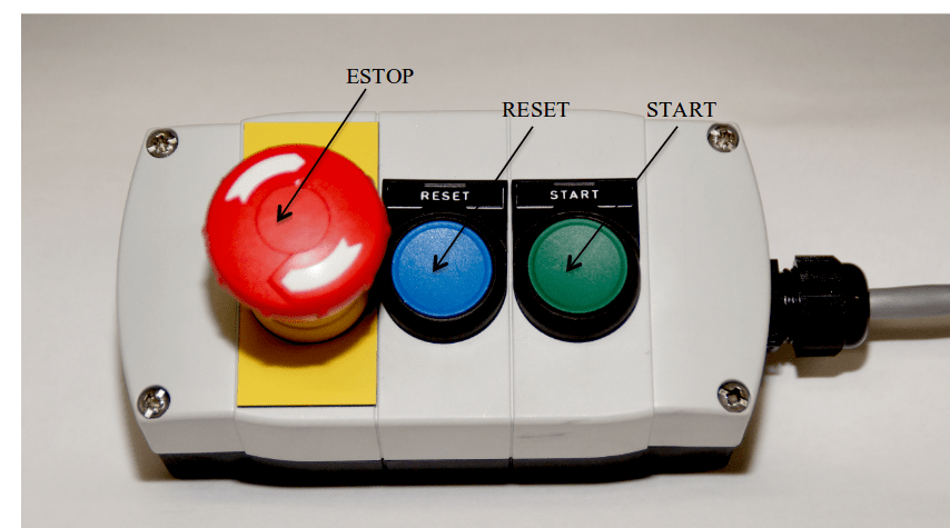
If they are ON , then this rotation allows the button to pop out to let you know they are now OFF. Check the second ESTOP , which must also be
rotated and popped out.
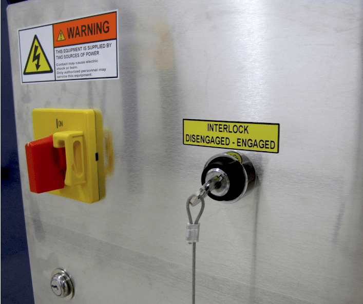
Interlock Key
The interlock key is located on the left side of power switch, which enables the spindle. It is having a key at the end of Tooth Holder, inserting the key to the engaged position will activate the spindle.
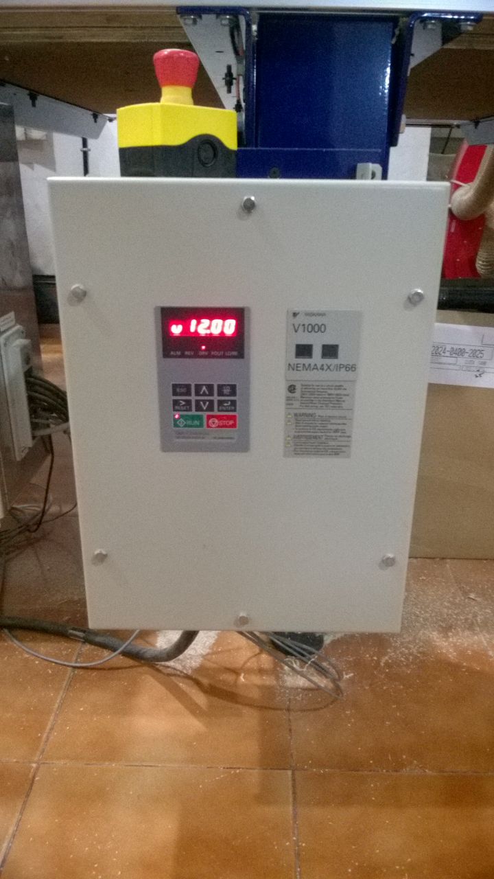
Spindle Control Box
The spindle RPM control board allows you to change the spindle rpm using the software. The controller is wired into Variable Frequency Drive (VFD) models and is connected to PC via USB. We can manually udjust the spindle speed by pressing the Up/Down arrows in the panel display. The figure below shows our control panel working on 12000 RPM.
Tools Required
The following tools are required to operate on Shopbot machine
- Partworks software
- ShopBot3 software
- End Mills
- Collets
- Covernut
- Drill set & screws
- Dust collector
- Wrentch
- Tooth holder
Partworks software
PartWorks and PartWorks 3D are ShopBot-specific versions of Vectrix’s V-Carve CAD/CAM software that will get you started quickly designing for CNC cutting and machining. It allows anyone with a ShopBot CNC tool to quickly and easily incorporate beautiful, decorative carved designs into their own products, for 2D cutting we are using V-carve Pro and for processing 3D model we are using Partworks 3D.
ShopBot3 software
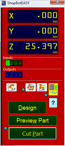
ShopBot3 is the control software for shopBot CNC, all the X,Y and Z axes movements and job processings are done through this control software. We can easily take the software from the start menu by clicking the ShopBot3 icon as shown below.

End Mills
An end mill is a type of milling cutter, a cutting tool used in industrial milling applications. It is distinguished from the drill bit in its application, geometry, and manufacture. While a drill bit can only cut in the axial direction, a milling bit can generally cut in all directions, though some cannot cut axially. End mills are used in milling applications such as profile milling, tracer milling, face milling, and plunging. The material of the bits are made on different materials, most common are solid carbide bits.
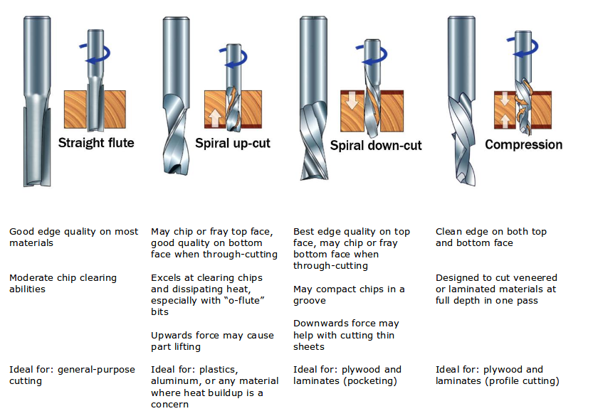
Flute types
There are four basic flute types: Straight, spiral up -cut, spiral down-cut, and compression. Each type has its own advantages and disadvantages, which are outlined in the chart below.
Number of flutes
The number of flutes on a bit is essential to calculating proper feed and speed rates.For most applications you can use a bit with 1, 2, or 3 flutes, but you must adjust your reed rates and RPM accordingly to maintain proper chip load.
End shape
Straight and up spiral bits come in a variety of end shapes Square ends are most common, and are a good choice for creating pockets and grooves, profile cutting, simple lettering, and drilling operations. Ball (or rounded) ends are best for 3D carving. V-carve bits are often used to create complex letters for sign making. They can also be used to chamfer edges and create countersinks for screw holes.
Chip Load
Chip load refers to the actual thickness of the chip cut by each revolution of the cutter. It is the measurement that all feed/speed calculations are based on. A spinning bit generates friction and heat as it moves through the material, and part of this heat is pulled away by the flying chips. A larger chip load pulls away more heat, but also puts more stress on the cutter.Each material has its own ideal chip load range that balances heat dissipation with cutter stress. View MoreChip Load = feed rate ( ipm ) ÷ ( cutting rpm x number of cutting edges )
Some of the bits we are using is showed below
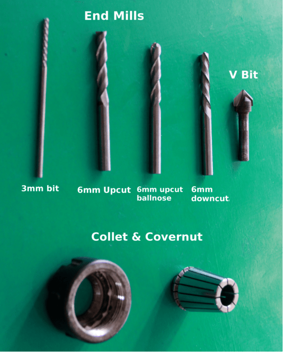
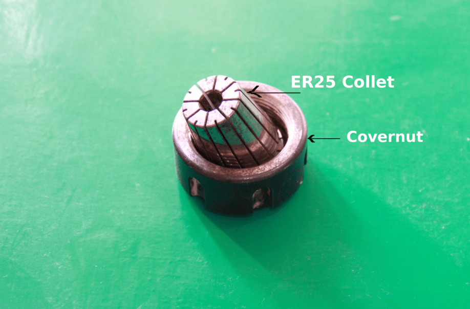
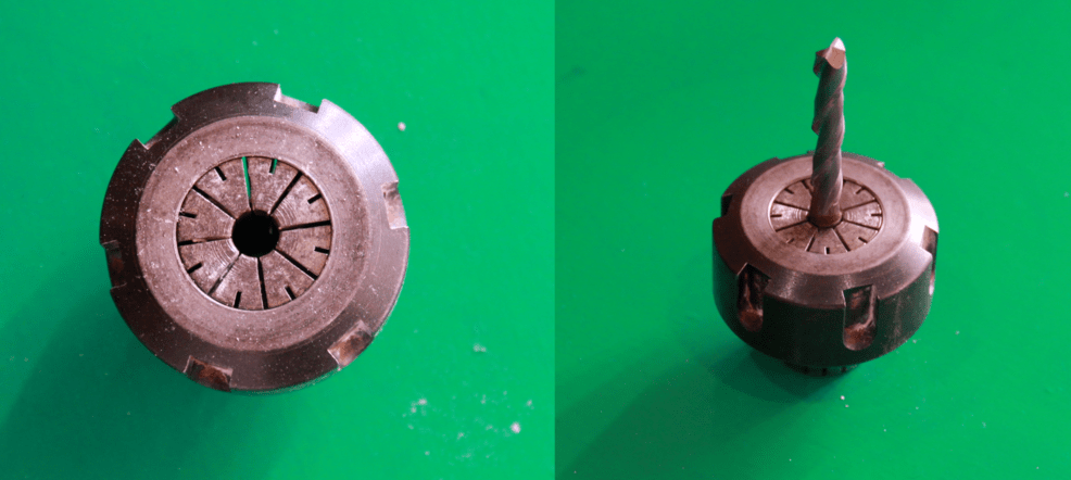
Collet and Covernut
A collet is a subtype of chuck that forms a collar around an object to be held and exerts a strong clamping force on the object when it is tightened. It may be used to hold a workpiece or a tool. We are using ER25 collets, ER collets are slotted (alternately) from both ends and therefore compress onto the cutter along the whole length of the collet when tightened. This not only provides a better grip on the cutter shank but also allows some variation (typically 1mm) in shank sizes that may be used in a single collet. The smaller size collets are best used to hold cutters no more than 0.5mm below the nominal size. Collets are inserted into the covernut.
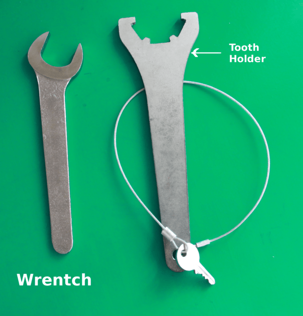
Wrentch & Tooth Holder
Tooth holder and wrentch is used to tightening the collet in to the spindle, you can identify them easily, tooth holder will have a key tied to it .
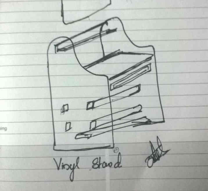
CAMM Stand
This week i decided to make a stand for our Vinyl cutting machine, we are using Roland CAMM-1 GX-24 machine and currently we are keeping it on a plane table. The height of the table is very less , So it is difficult for the users to operate on this easily. My plan is to make a stand with appropriate height to operate in the machine easily, laptop tray and can hold vinyl sheets. I made a rough sketch of it on my diary as shown below.
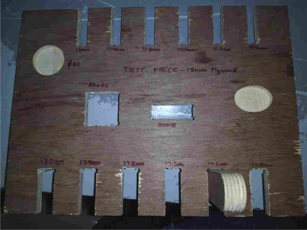
Test Cut
This is the test part we made inorder to find out the tolerance parameters for the pressfit. Designed it in rhino with different dimensions for 18mm and 12 mm plywood sheets like the one shown below. This was done in 18mm plywood sheet and tested pockets, rectangular cuts etc to check the parameters. The piece was cut on shopbot with 6mm upcut bit and checked the tolerance and found that for 18mm plywood 0.5mm is good for pressfits and for 12 mm plywood 0.4mm tolerance is good enough.
Design
The designing part is little bit tougher part for me, I opted Rhinoceros for the design. Inorder to process the design in shopbot we need a 2D drawing and later it will be assembled. I have gone throuh the manual of Camm-1 GX24 Roland vinyl cutter and noted the installation space for it the space requirement is shown below.
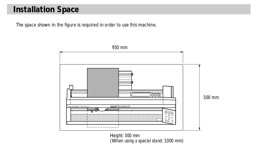
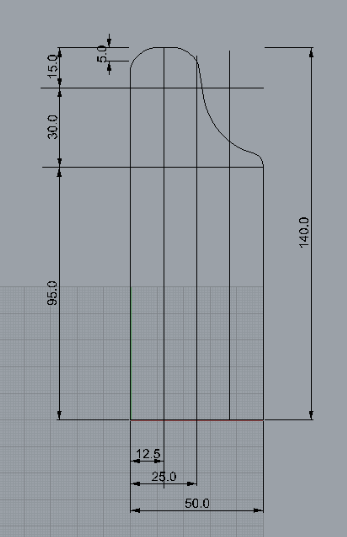
Based on this i have given the dimension of my Viny stand as length = 950mm, Height = 1400mm, Width=500mm the sketch am copying here from my design for the dimensions. Selected the plywood 18mm for doing the stand.
The stand is having different parts , I have divided the total design into eleven parts as listed below for easy identification and will brief about each one.
| 1. Side Plates |
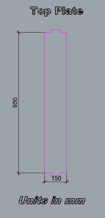
| 2. Top plate |
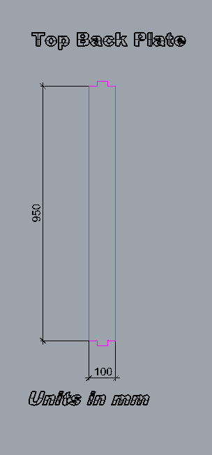
| 3. Top Back plate |
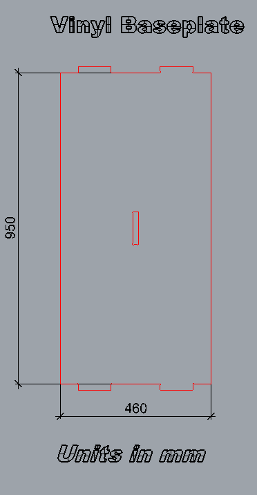
| 4. Vinyl base plate |
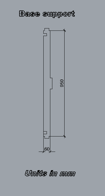
| 5. Base support |
| 6. Laptop tray |
| 7. Sliding support |
| 8. Bottom Plate |
| 9. Vinyl holder |
| 10. Holder supports |
| 11. Front panel |
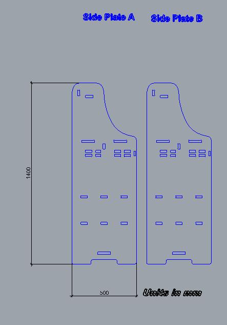
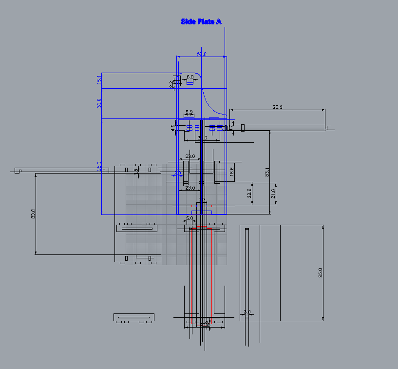
1. Side Plates
These are the main plates which holding the machine and other supports, two such parts are there in 18mm, given the tolerance of 0.5mm to the slots as calculated from the test cut. This is the main structure of my stand all the parts are attached into this part,two parts are of same dimensions.
2. Top plate
This is the top most part of the stand where we can keep small things like speakers, or usefull small items,tools etc in it. It will connect the two sideplates horizontally. Material is 18mm plywood.
3. Top Back plate
Vertical member of the top plate which connects the two side plates and both top plate and back plate will keep the items safe from falling towards the back end. This is also in the same dimension except the width is smaller than the other.
4. Vinyl base plate
This plate will hold the machine, thickness of material used is 18mm plywood. Designed based on the spec from the roland GX24 user manual. It is having a length of 950mm and width of 500mm. placed horizontally, supported by base support member.
5. Base support
This will support the vinyl base plate vertically, main fuction is to hold the base plate.
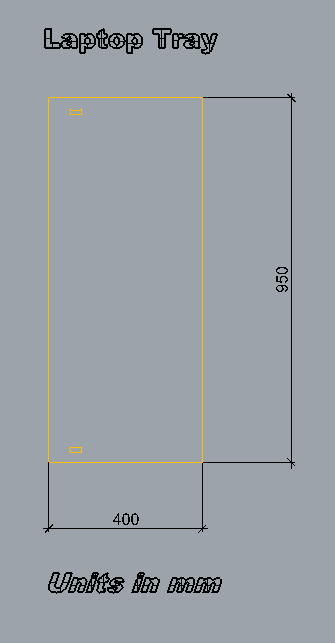
6. Laptop tray
Actally in my plan this was not there, while doing the design i thought that if i design the stand foe vinyl, the machine will sit in a height of around 1 meters, then using a computer is very difficult to operate, So i later included this also in the design, i haven't gone through any design rules and still not sure about the stability and working of the laptop tray. I was confident in my concept, that's why i implemented this. The tray is placed in between the two channels on each side , I selected the 12mm material for tray , accordingly given the channel slots and lock for the tray. The bottom channel is interconnected to the other channel on the other side plate.
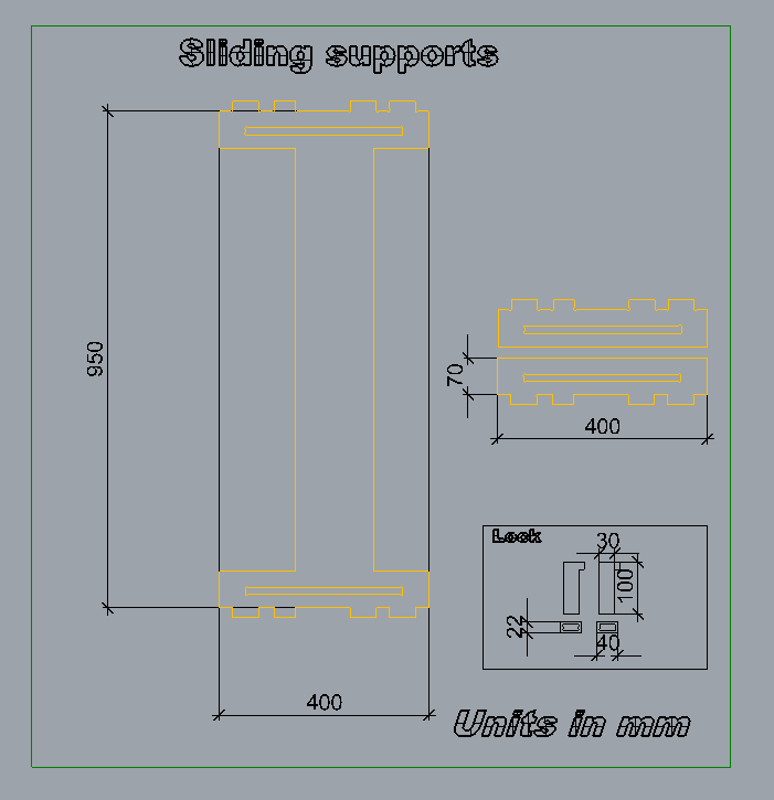
7. Sliding support
The main function of this is to supprt the tary and movements of the tray as explained above, and in addition included a lock in 12mm plywood for the tray to prevent the tray comming out from the channel.
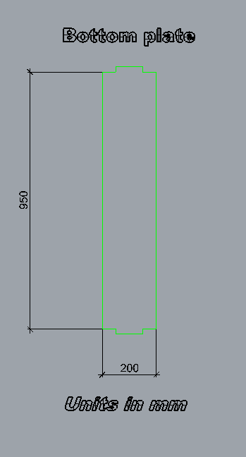
8. Bottom Plate
The bottom plate will function as footrest and support for the sideplates, material is 18mm.
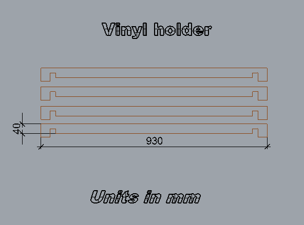
9. Vinyl holder
This part is to holding the vinyl rolls, first my plan is to make a circular structure to hold the vinyls due to time constraints i have done this simple holder . Material selected is of 18mm with a height of 40mm. This part will increase the strength of the total structure by connecting the two sides.
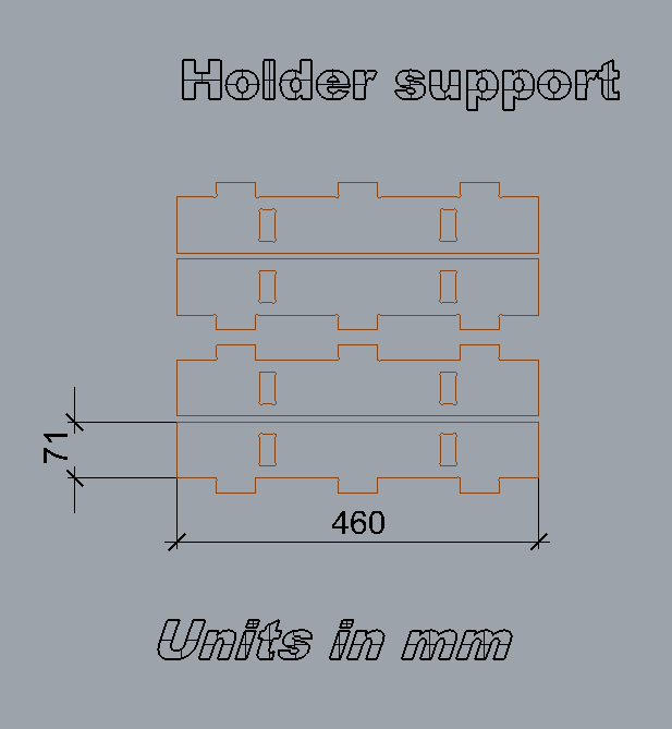
10. Holder supports
This part is for holding the vinyl holder, two vinyl holders acn hang in each support,like this two parts are there in each side.
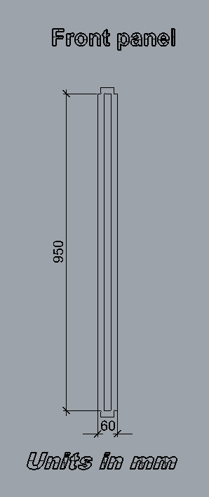
11. Front Panel
Front panel is placed in the laptoptray, the laptop tray will rest on this plate and will help the uniform movement of the tray. I have selected 12mm plywood for this part.
Finishing the Design
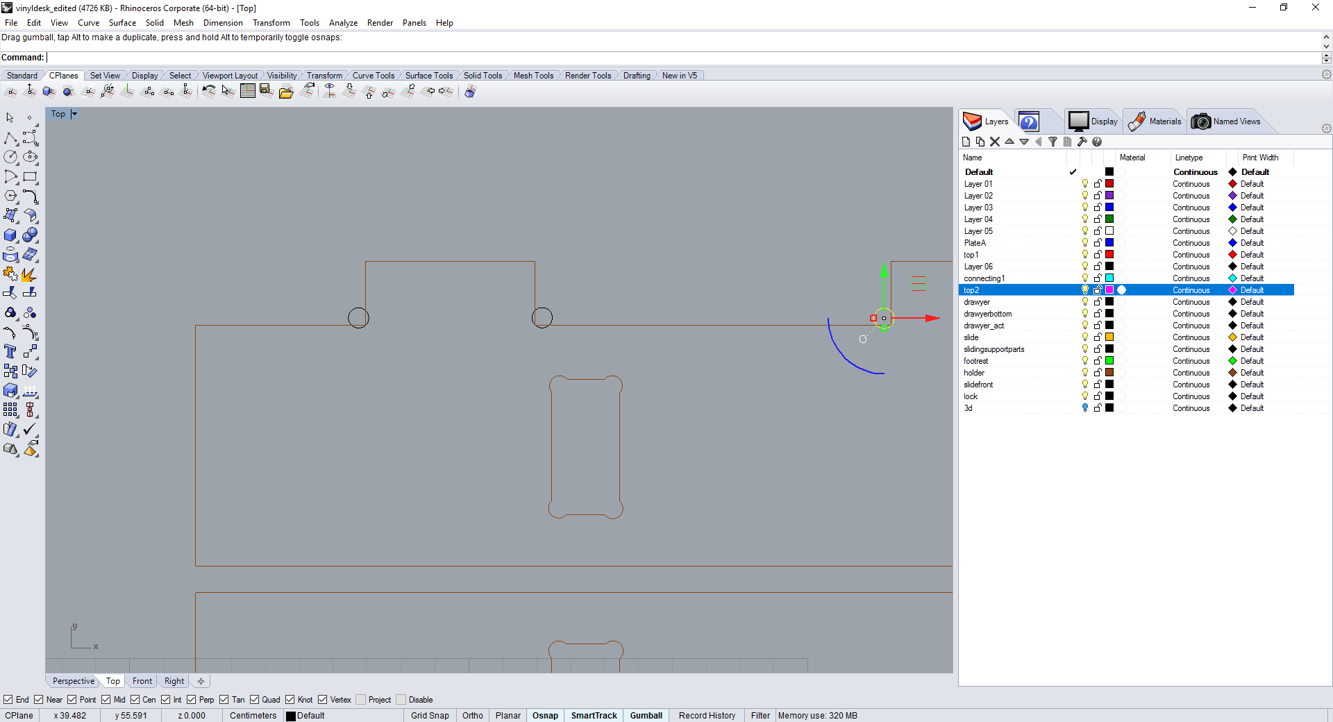
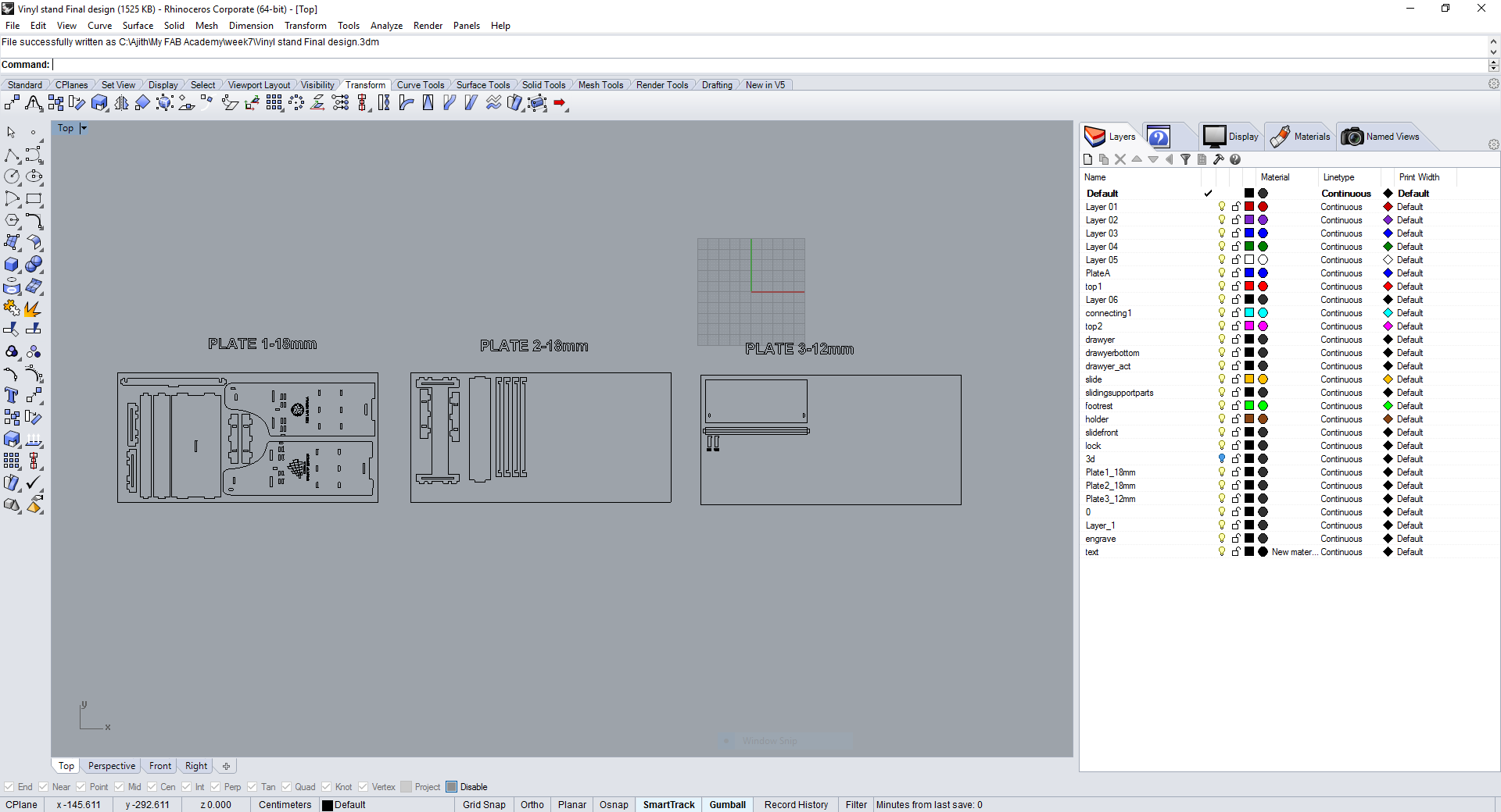
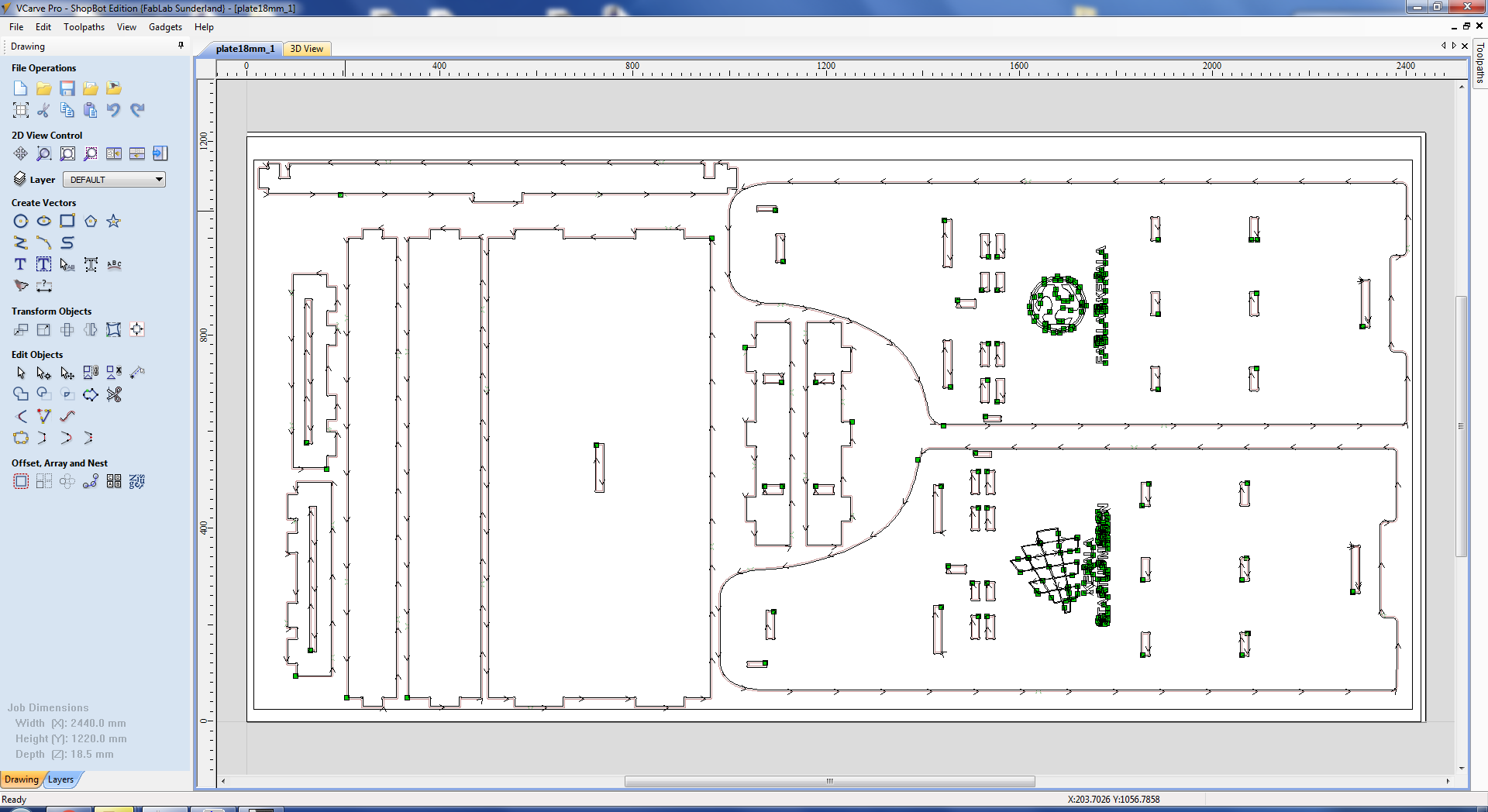
The entire design takes nearly 6:00hours to design, everything is designed based on the main side plates. Completed the design in rhino arranged the parts in the plates, so that we can cut the parts in the shopbot. The design plates are arranged and labeled by its corresponding names. Added the Fab Lab Kerala logo on one of the side plate for engraving and in the other side given the logo of Fab lab .I used this logo, for opening this in rhino i opened it in Inkscape and converted it into .pdf format so that it will open in Rhinoceros. Opened the pdf file and scaled down it to my side plate and using the text tool i have enetered "FAB LAB KERALA", Like this the logo of Kerala Startup Mission also put on my design. Each parts were changed to individual objects layer. The below shown picture is the screen shot from my design drawing, it is very difficult to understand because so many lines are there that's why alreday explained each part seperately in the above section.
Finalising the Plates
After arranging all the plates , Next i have done some editings to process it in shopbot, The parts with 90degree lines won't cut correctly beacuse the bits are of circular shape and during the profile cuts it will be cut curves instead the 90 degree edges, inorder to avoid this we have to place a dog bone like shape in the design or manually we can place a circle with a diameter equivalent to the cutting bits dia. Here i am going to use 6mm bits so i have given 6mm dia circles and trimed using "Trim" command and joined the parts after trimming as showed below.
The image shown below is the complete plate arrangements of my CAMM Stand.
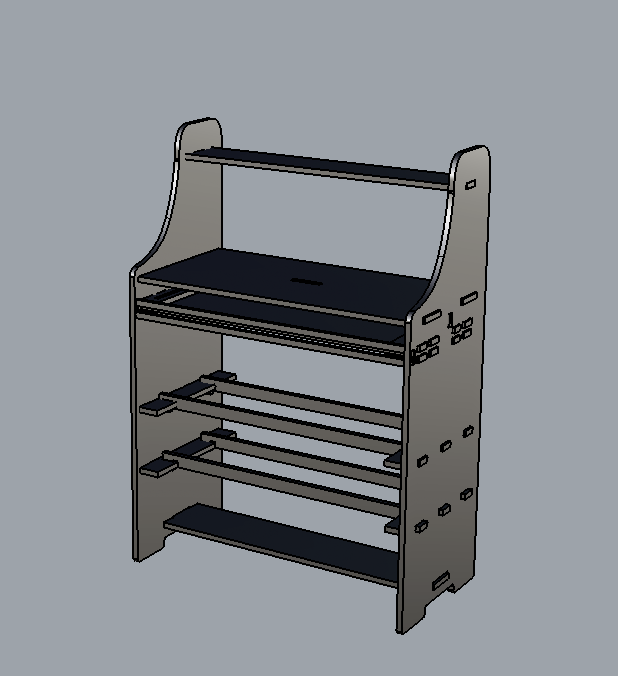
3D View of Vinyl Stand
Once the design is completed, we have to verify the designs otherwise the material will be wasted. We can do a test cut in cardboard sheet with a scle down version
this is the easiest method to confirm our designs. First i thought to cut the design in the laser cutter, but i extruded each parts in 3D and assembled manually, it is little bit
tough thing to assemble but i did the assembling. In my case i was confident about my design. Extruded each part using "Extrudecrv" command in rhino and made all 3D parts assembled and
confirmed my design. 3D view of my stand is shown below.
Moving on Shopbot
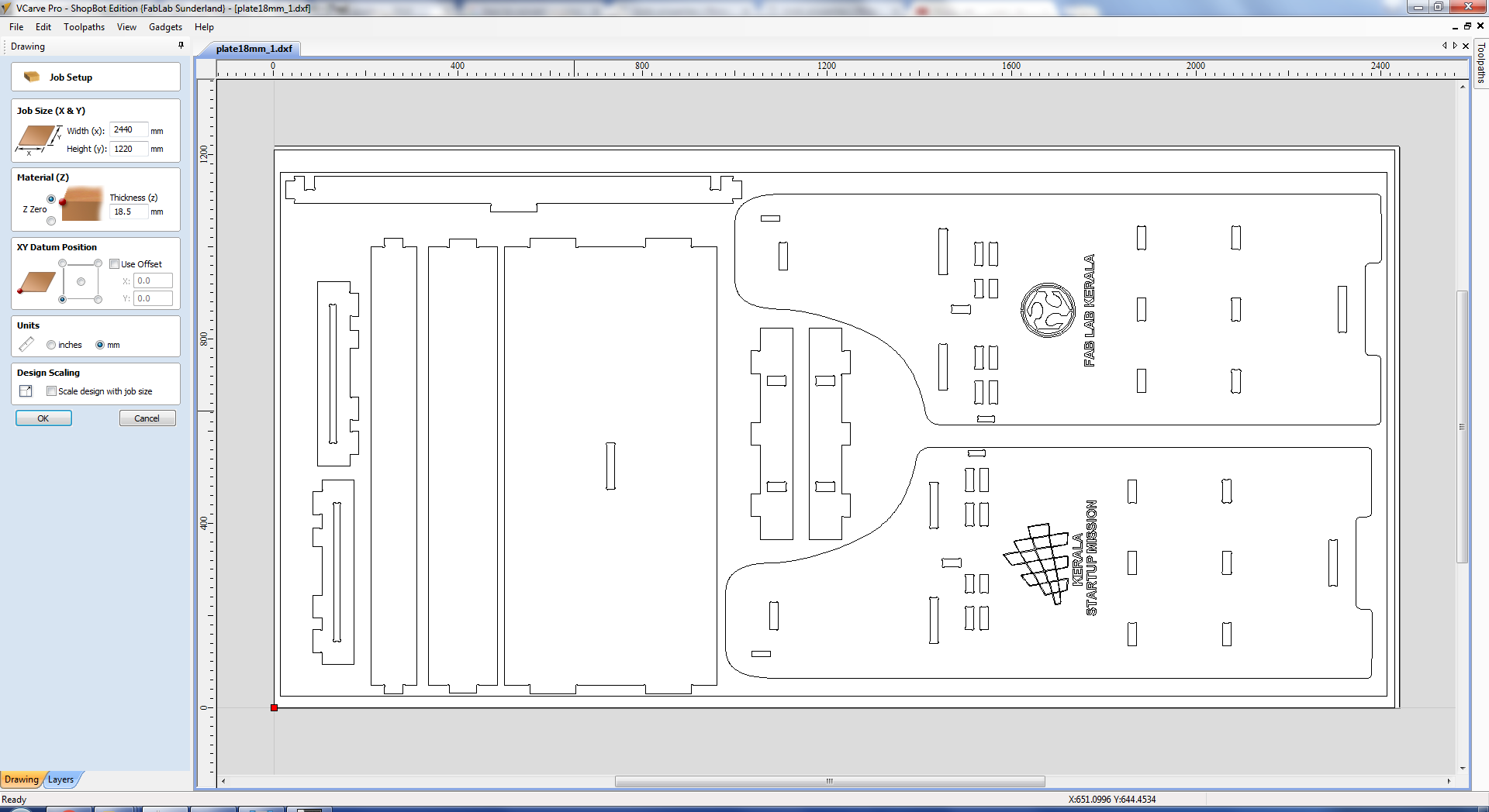
Now i am ready to machining vinyl stand design in ShopBot, Arranged plates from Rhino exported as ".dxf" format and saved in my folder, Next opened "VcarvePro" the software of shopbot for 2D cuttings. Actually i designed the parts in Rhino as large objects centimeters but while opening it got scaled down to millimeters. Then i changed the units in rhino file to mm and then converted to .dxf format. Once opened it will be directed to job setup window, In that we can see the job size(X,Y) ,Material thickness(Z),XY datum positions etc, out of which I have given the Job size as the maximum bed size of our machine i.e 2440X1220mm. Material thickness(Z) selected as 18.5mm the 0.5mm extra is to cover the unevenness of the material, plywoods will have different thickeness in different places. Next is XY datum positions this is actually an offset , if you put some offset the job will start from the offseted postion instead from the origin. I have selected Zero offset. Next is units, by default it was mm and i haven't done any scaling so leaved the scaling option as such.
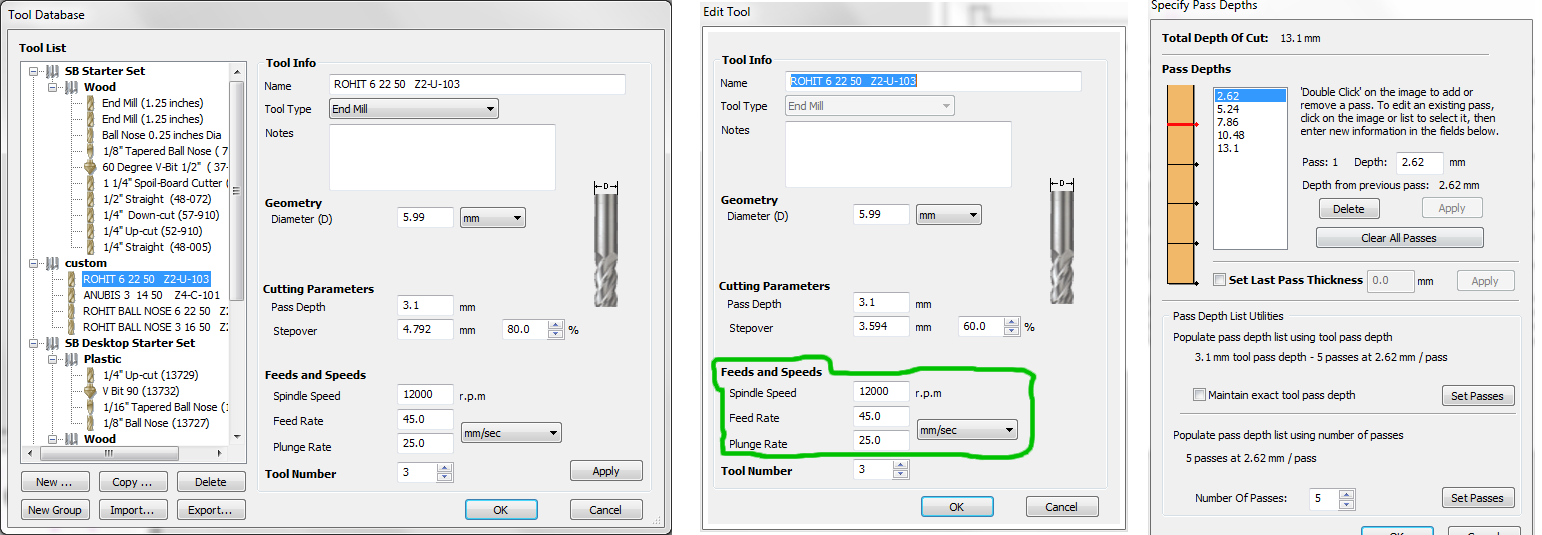
These are the bits settings, especially the feed rate, spindle speed,plung rate etc given for my job. It is marked with green color. I have selected the 6mm Upcut bit and selected speed of spindle as 12000RPM, Feed rate of 45mm/sec and plung rate of 25mm/sec.
If you click the next window will open in that we can edit the pictures and draw newer shapes using the tools available in the window, the exported .dxf file was not joined , So i joined all the lines using the join tool from the tools by selecting the multiple lines. Once done from the Toolpath menu available on the right corner of the window , using that you can select different profile paths, for my case already i fixed the bed for cutting. From the window,first i selected the engraving path and selected the 90degree V bit and given 1mm engraving depth and simulated the profile path. Next selected all the slots and first selected the bits , we are using a local 6mm bit and 6mm ER25 collet for cutting. The slots needs to be cut inside so selected the cut inside option and calculated the profile path. After that selected the outer shpares and selected the bits, cutting depth, number of passes, added tabs into it inorder to support the parts removed while cutting. All the settings are given and completed the profile calculations. We can see the simulation of the job in the 3D window. After that saved the individual profile shopbot files to a folder along with the Vcarve file.
Machine Setup
Followed the steps to operate ShopBot machine.
Step 1
Walk around the shopBot and make sure that there are no wires/ any other items on the bed that Obstruct the operation of Gantry.
Step 2
Turn On the ShopBot machine by turning the Red button on the control box as mentioned earlier. Ensure the ESTOP swicthes are in the OFF position
by rotating the Dongle buttons in anticlockwise direction.
Step 3
Double click the shopbot 3 icon from the desktop or select from the start menu to launch the contol software. Select the X,Y keypad from the control software
and move the machine to the X & Y direction. Some times one error message will be displayed like "ESTOP button is ON". Then click the blue reset button on
ESTOP switch dongle. You can move the gantry in up/down to move in Y direction and Right/left movement will allow you to move the gantry in the X direction.
Step 4
Select the appropriate Bits, Collets and covernut to be fixed in the spindle, In my case i have selected 6mm Upcut bit, ER25 type 6mm Collet and Covernut. You can insert the collet in covernut and the bits can be inserted into the collet, proper clearence is required for the bits. It is showed below.
Step 5
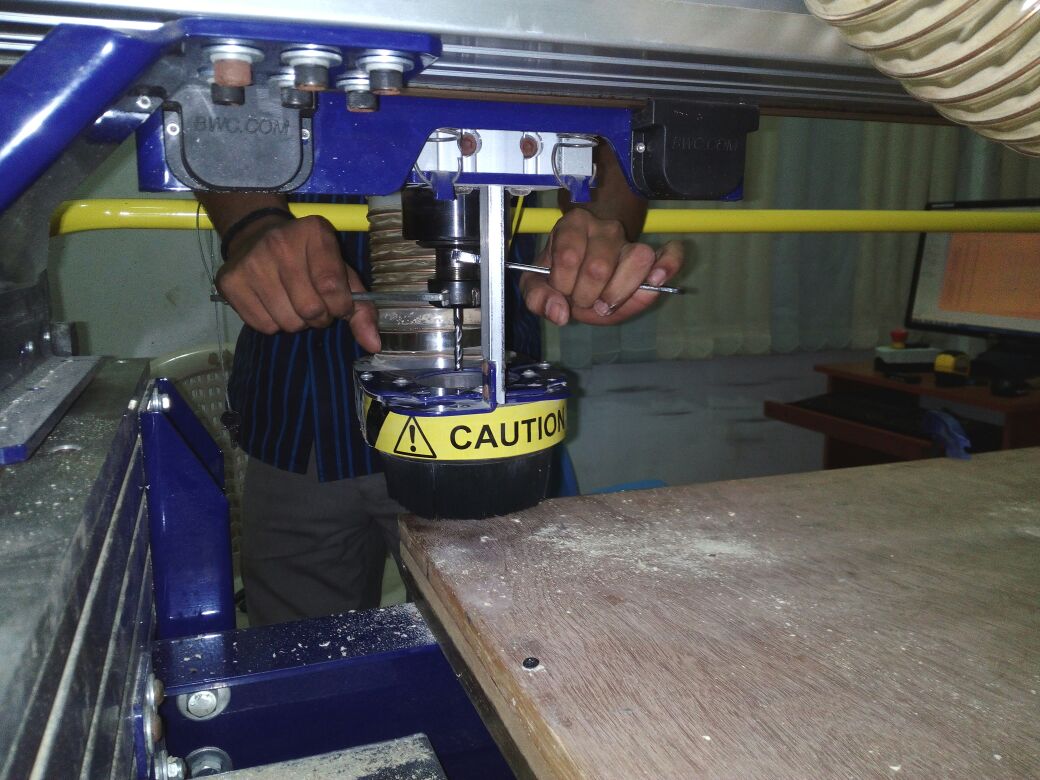
After fixing the bits the collet can be placed in to the spindle, here you can use the tooth holder and wrentch for tightening or loosening the collets. Unscrew the THUMB SCREW to lower DUST SKIRT covering over SPINDLE. This makes it easier to access the spindle assembly, turn the covernut assembly anticlockwise direction into the spindle threads loosely until you cannot move it further. Use the Tooth holder and Wrentch as shown in the picture below and rotate the tooth holder and wrentch away from each other to tighten it. Do not overtighten it. The reverse movement will loosen the assembly. After this raise the Dust Skirt and tighten the thumb screw.
Step 6
Ensure the bits are correctly tightened , then using the shopbot3 software move the gantry in X & Y direction for setting the origin.
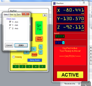
Once you selected the X & Y origins now we have to zero the X,Y axes by select the Zero axes button and select x & Y axes then press Zero. Now our
X& Y axes are zeroed.
Step 7
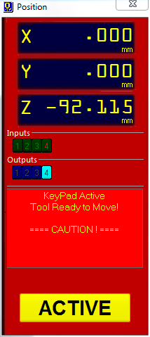
After this we can set the Z axis, To set the Z AXIS, move the Shopbot to the desired position by clicking on the keypad icon in the control panel interface
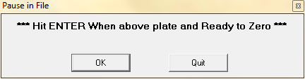
move the spindle roughly to the center of your final layer where you will place your aluminum plate. Once you have your SPINDLE at some position, click "ZERO Z AXIS W/ Z PLATE"
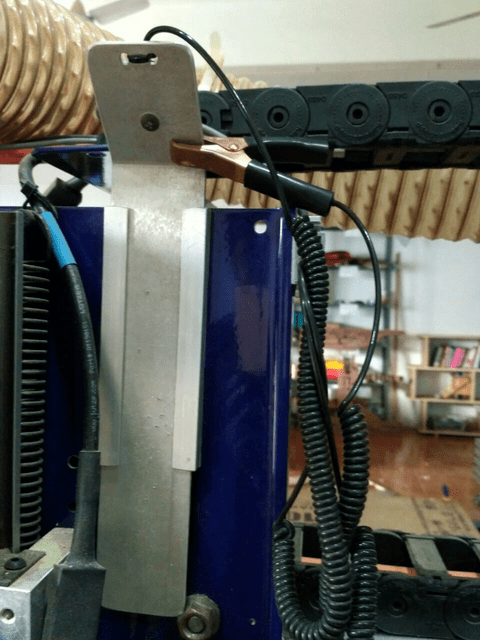
from the console and wait for the dialog box like the one shown below. Establish a good electrical ground between the alligator clip and a metal surface preferably on the frame
of the ShopBot, such that both alligator clip and metal surface make contact.
Next take the aluminum plate out of the side pocket next to the
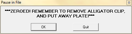
SPINDLE assembly. Place this plate on the final layer underneath the end mill Click OK when you ar ready for the spindle to go through a 2 step cycle of lowering and raising itself until it touches the
aluminum plate twice and will show a message saying Z axis Zeroed, you can replace the aluminium plate and copper plyer back to the frame and click OK.
Step 8
Next select the cut part option from the console and select our profile files, enable the spindle by turning the Key and press the Start cutting option
from the contol software this time a message will be displayed saying that first turn ON the spindle and the click "OK". Firstt we have to press the START button on the
ESTOP dongle and then press OK, otherwise the spindle will be in OFF condition and the machine starts milling, then the bit will break. Once you pressed OK , Turn ON the Dust collector and wear safety glasses,ear plugs etc.
Shopbot on Action
Once you made everything, go to the console and click the cut part select the Shopbot files you saved(.sbp) file and click start by this time one pop will come warning that after pressing the start button only you have to press OK then our job will start. It started with engraving in my stand parts.
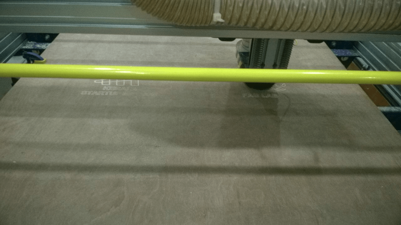
After engarving
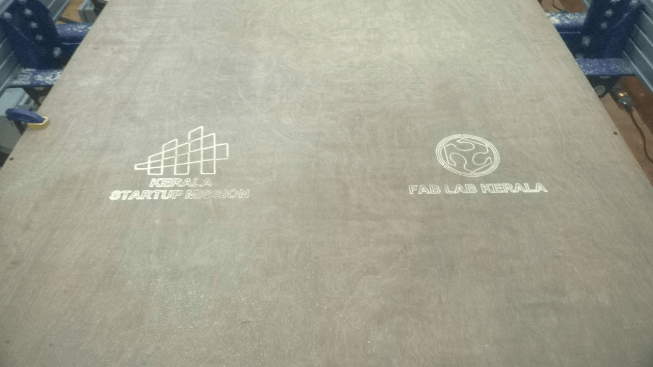
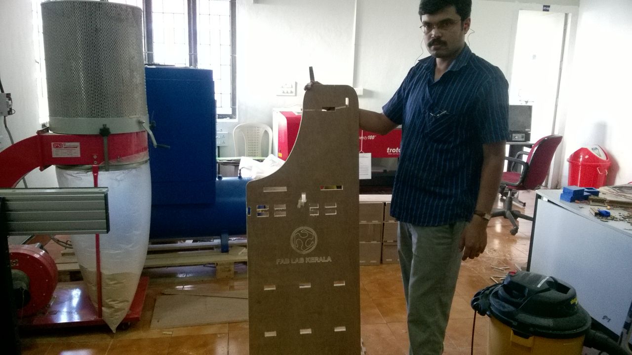
The below figure shows the completed part of my first plate.
Like this i have done the other 18mm hlaf sheet and a small portion of 12mm piece to complete my model.
Assembling
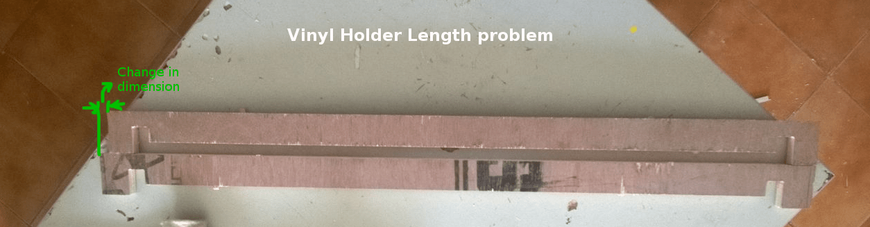
After the cutting some issues were there, The tolerance i had give is 0.5mm but it is too tight for me, so it takes a lot of effort to file the extra dimensions. In the vinyl holder a small dimensional error happened, the length was not proper so i cutted it using the band saw and corrected in to my required dimension. correceted everything and assembled all the parts togather as shown below.
This is the problem i faced, i removed the extra dimension using the band saw.
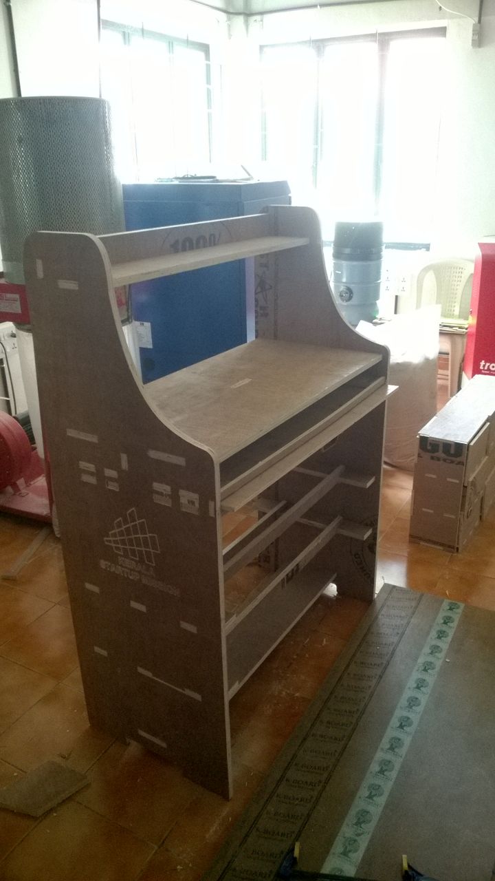
The picture shown below is my Camm stand after assembling.
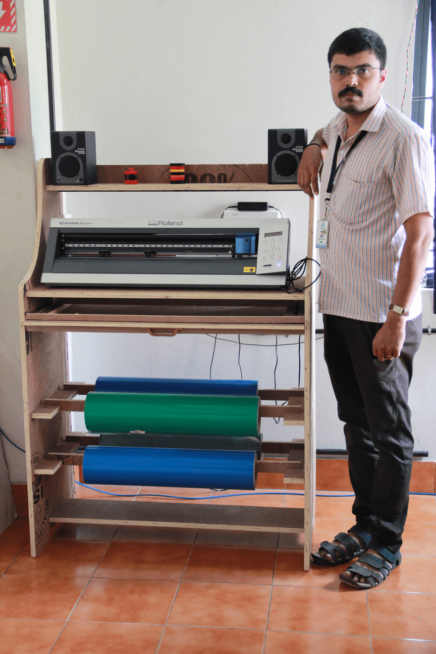
Finally i moved the stand to the vinyl cutting area and arranged the machine over it . Filled Vinyl rolls in the vinyl holder. Here is my Hero shot of my CAMM Stand.
Download My Vinyl Stand production files (.zip)
Extra Assignment
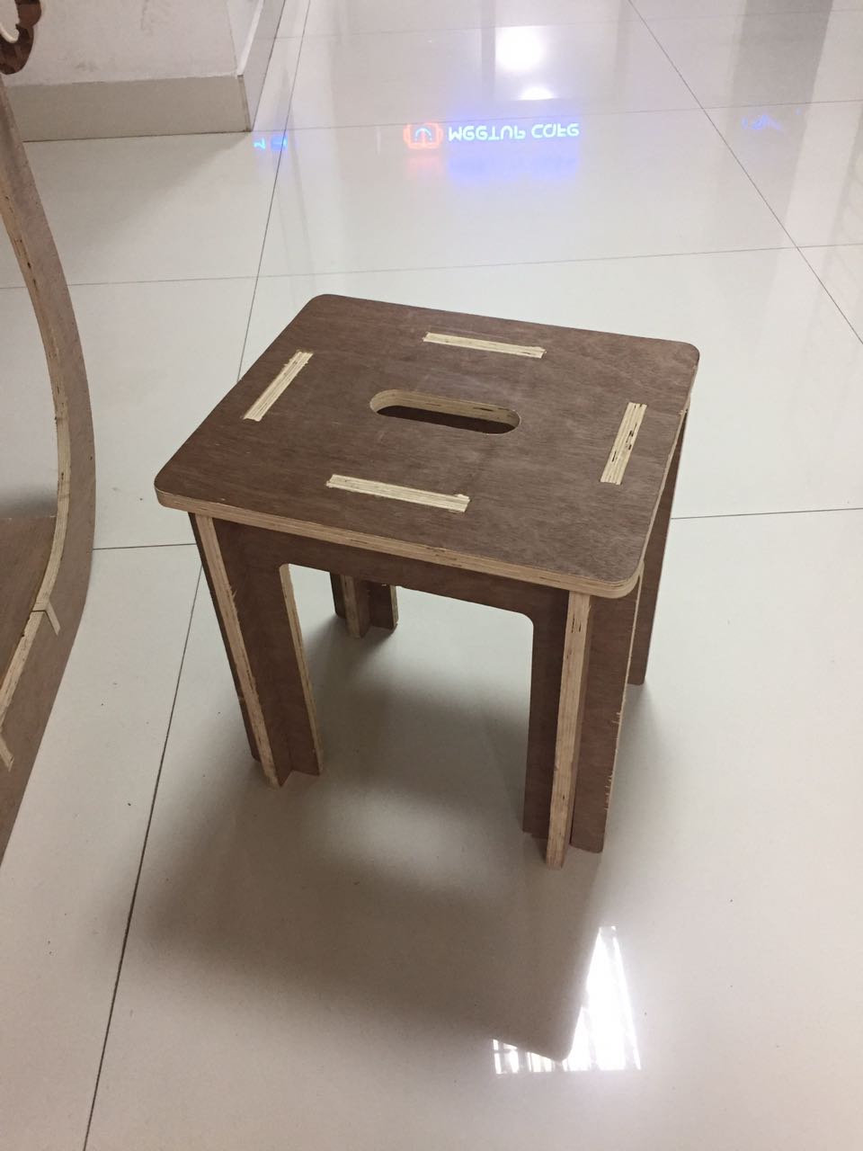
Stool
I made this stool last year for our future technology lab use, mainly made for general purpose use. Similar design i have seen in internet and inspired from that i designed it in Rhinoceros software and made it using shopbot. The requirement was to make a general purpose stool, So i have given preference to the strength of the design rather its shape. Actually this contains mainly three parts. One top , and two side parts.The sketch of my design is shown below..
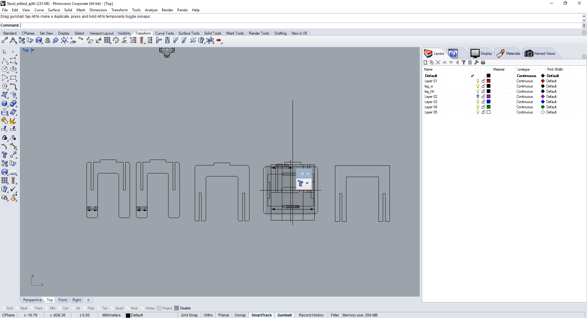
First i made the design in rhinoceros, the drawing is made in 2D and extruded individula parts using "extrudecrv" command in rhino and assmebled it and verified that all the dimensions are correct and it is perfectly fitting. This is my first attempt in shopbot , So to avoid risk, i thought to make a scale down version of it in laser cutter. The parts were exported to .dxf format and opened in inkscape from there i scaled it down and done some editing to the slots width and joined the splitted lines. Finally converted the file to be cut into trotech speedy 100. The parts were cutted in laser cutter using 4mm ,3ply carton sheet and after cutting assembled all the parts. This time i was very happy that my first attempt was success, except the slots were too loose. The picture shown below is the assembled part in cardboard sheet.
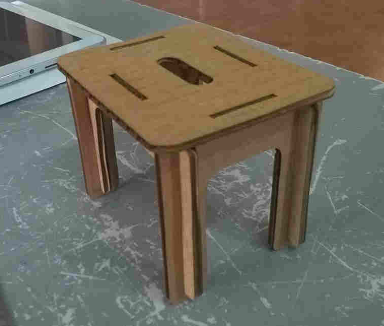
After that i eported the file into .dxf format and opened it in V carve software, done editings for machining and set the profile paths , saved it individually and processed in shopbot. Finally completed the machining and assembled the parts, the dimensions were too tights so used rubber hammer to press fitting it. The hero shot of my stool is shown below.