WEEK 5
3D SCANNING & PRINTING
ASSIGNMENT
- Test the design rules for your printer(s) (group project)
- Design and 3D print an object (small, few cm) that could not be made subtractively
- 3D scan an object (and optionally print it)
Preperation
This week Assignment main aim is to learn about 3D printing and design a small object that cannot be made subtractively and doing 3D scanning. Neils lecture about the 3D printing technologies was more informative got a chance to update my knowledge in this area. I refered fab academy archieves to learn what are all the things the fabbers made in previous years. In our lab we have two 3D printers Ultimaker 2 and Dimension SST1200es 3D printer for printing in plastics both are working fine.
3D Printing
3D printing is a additive manufacturing process of making three dimensional solid objects from a digital file.The creation of a 3D printed object is achieved using additive processes. In an additive process an object is created by laying down successive layers of material until the object is created. Each of these layers can be seen as a thinly sliced horizontal cross-section of the eventual object.
To Know more about3D Printing
How it works?
It starts with designing the object in designing softwares. There are a lot of sofwares available to designing the objects both open source and licennsed one's. Once the object is designed it has to be sliced for 3D printing with a 3D printer. Slicing is a process of dividing our designs into hunderds or thousands of horizontal layers. Some modeling softwares has the ability to slice our designs also some of the 3D printers have its own slicing softwares like "Cura" for "Ultimaker" 3D printer.
3D Printing Technologies
All 3D printing technologies create physical objects from digital designs layer by layer, but each using different methods. American Society for Testing and Materials (ASTM) group “ASTM F42 – Additive Manufacturing”,developed a set of standards that classify the Additive Manufacturing processes into 7 categories according to Standard Terminology for Additive Manufacturing Technologies. Different 3D printing Technologies are listed below

View these links to know more about each
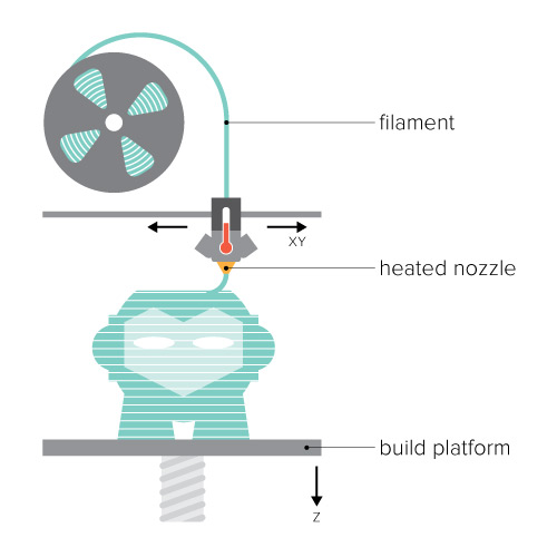
Fused Deposition Modeling (FDM)
Here i am writing a little about Fused Deposition Modeling (FDM) method because we are using the plastic 3D printers which are FDM based one. In FDM we are using a filament in coiled form it is fed to the head of the printer in which a nozzle is sitting the nozzle will be heated to melt the materials and the head will move in the horizontal and vertical directions. Here the bed is acting as the Z axis. All the machine working are controlled by an electronic control board.This technology is most widely used with two plastic filament material types: ABS (Acrylonitrile Butadiene Styrene) and PLA (Polylactic acid). Though many other materials are available ranging in properties from wood fill to flexible and even conductive materials. FDM is a great choice for quick and low-cost prototyping and can be used for a wide variety of applications.
Fused Deposition Modeling
3D printers in Our Lab
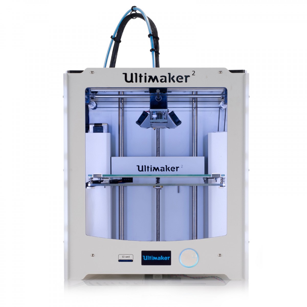
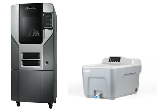
We have two 3D printers in our lab one is Ultimaker2 3D printer and Dimension SST1200es which is a soluable support technology printer by Stratasys.
Ultimaker 2 is a FDM based 3D printer by Ultimaker. It comes equipped with a heated build platform and can print at a resolution of up to 20 microns. It supports both PLA and ABS and can print at a speed of 300 mm/s. It is having a build volume of 223 mm X 223 mm X 205 mm. Cura is an open source slicing software for Ultimaker.
Dimension SST1200es 3D Printer
Dimension 3D printer is another printer which is working on FDM method and is a soluable support type printer by one of the pioneers "Stratasys" It is a ABS plastic based printer. These type of printers are soluable support type 3D printers . Support structures were early solutions to problems stemming from gravity these are some rigid structures erected in a lattice next to the object being printed and can be breakout after the print. Supports are extra material that act as “scaffolding” to hold a design in place if there is nothing beneath it to build on. Depending on your design, supports may needed to prevent filament from drooping when it’s printed, but after the print is complete, the supports can be broken off and cleaned up to leave you with your final design. In most cases, the supports are automatically generated by the slicing software that converts our STL file into a format the 3D printer can read, called G-code. In soluable support technology a seperate apparatus is used to remove the support structure from the printed parts. The finished part is dipped in a chemical filled inside the appartus and boiled after a few hours the support material will be dissolved in the tank and will get the actual part. We have Support cleaning Apparatus SCA1200HT came along with our 3D printer.
Testing the Design rules of 3D printer
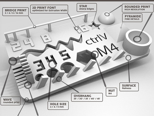
Understanding our 3D printers limitation is the most important thing because this may reflect the actual print quality of our prototypes/products. One of the main parameters is the resolution, it determines the quality of print. I found in Make magazine website regarding a shootout called Digital Fabrication Shootout they have ranked different manufacturers 3D printers. We have downloaded a test print model from thingiverse and is shown below with the test parameters.
- size: the object is 2x50x30mm (baseplate)
- hole size: 3 holes (3/4/5mm)
- Nut size: M4 Nut should fit perfectly
- fine details: pyramide, cone, all numbers
- rounded print: wave, half sphere
- minimum distance & walls: 0.1/0.2/0.3/0.4/0.5/0.6/0.7mm
- overhang: 25°/30°/35°/40°/45°
- bridge print: 2/4/8/16/mm
- surface: all the flat parts
You can download the test file from this Link
After downloading the file opened the .STL file in cura and printed in Ultimaker2 3D printer. It tooks 30 minutes to print the file in Ultimaker.
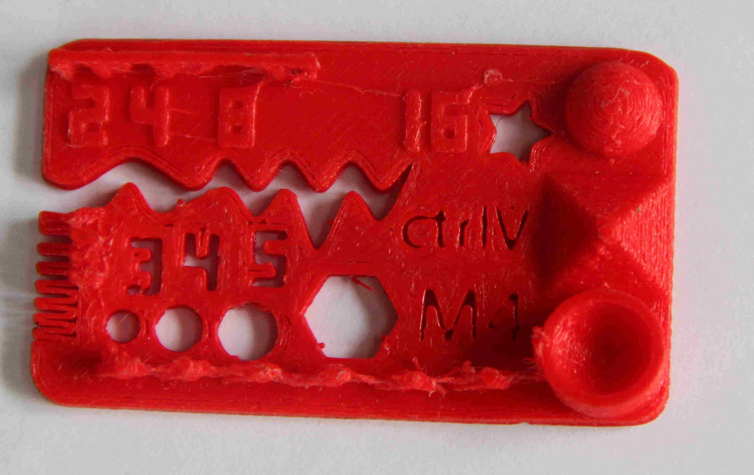
Initial visual inspection was carried and found it was a fine print. We have to do deatiled measurements physically then only we can conclude the results. Below showed test results are my observations from the above smaple 3D print.
Test Results
| Sl.No | Paremeters | Visual Inspection | Physical Inspection |
|---|---|---|---|
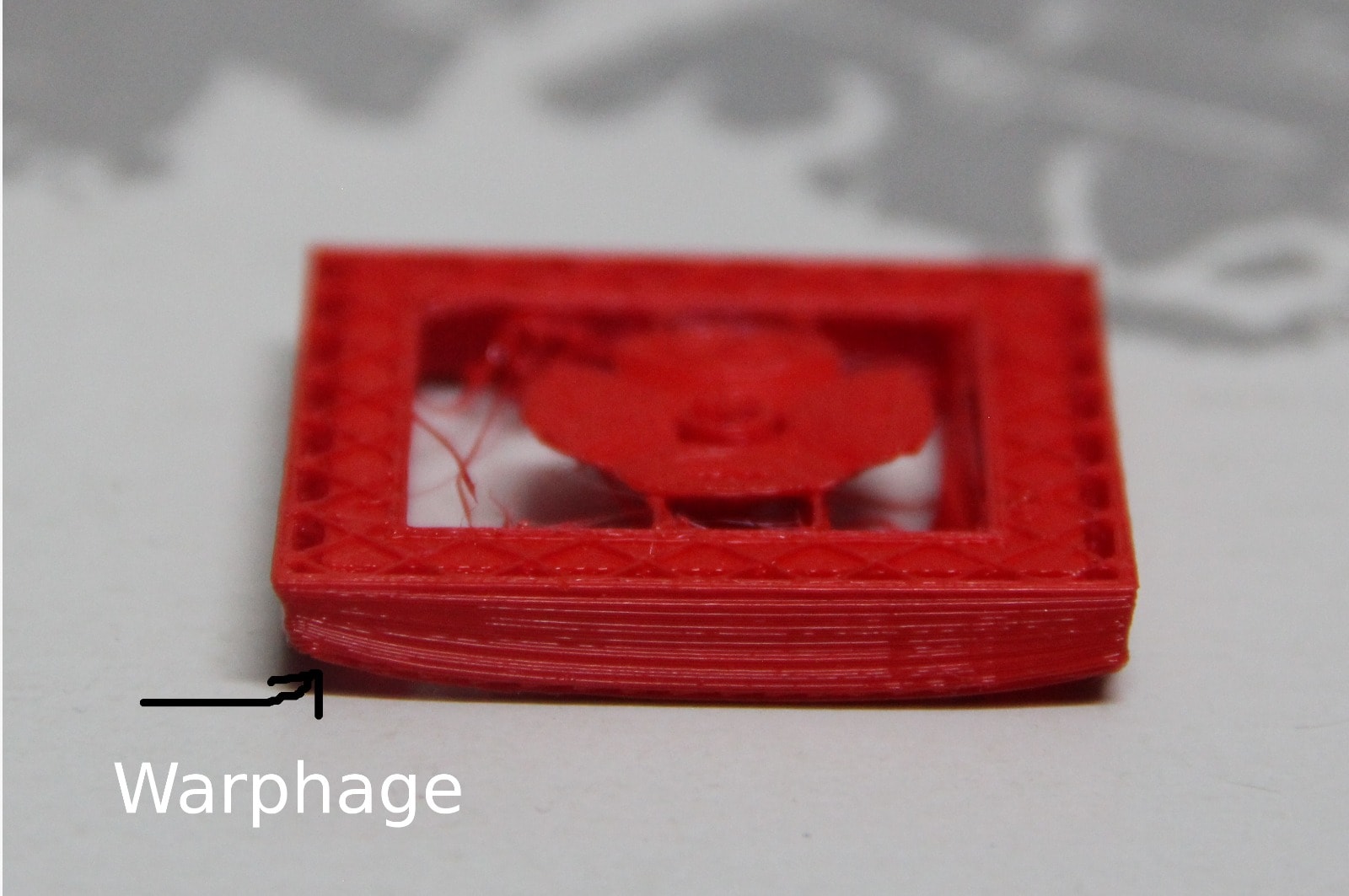
| 1 | size: the object is 2x50x30mm (baseplate) | Size is OK, small warphage at corners | 1.6X48.83X28.9mm |
| 2 | hole size: 3 holes (3/4/5mm) | Visually OK | 2.7/3.84/4.74mm |
| 3 | Nut size: M4 Nut should fit perfectly | Visually OK | Can't fit the nut(deviation=1.2mm) Hole dia 6.6mm,Nut dia 7.8mm |
| 4 | fine details: pyramide, cone, all numbers | Visually OK | Minor deviations | 5 | rounded print: wave, half sphere | Visually OK | Printed correctly | 6 | minimum distance & walls: 0.1/0.2/0.3/0.4/0.5/0.6/0.7mm | Visually OK with minor defects | Exact measurements not taken but visually all printed | 7 | overhang: 25°/30°/35°/40°/45° | small breaks in walls | Visually verified,OK | 8 | bridge print: 2/4/8/16/mm | Visually OK | 2/4/8mm came correctly,16mm easily brokened | 9 | surface: all the flat parts | Visually OK | Small warphage at corners |
3D Designing and Printing
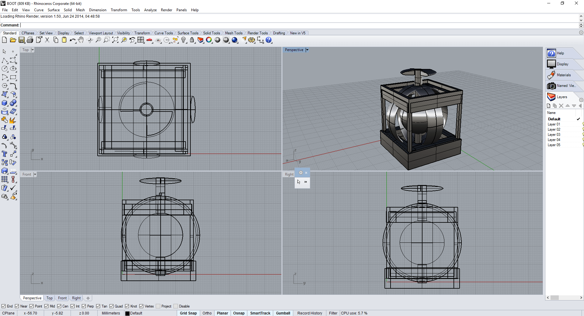
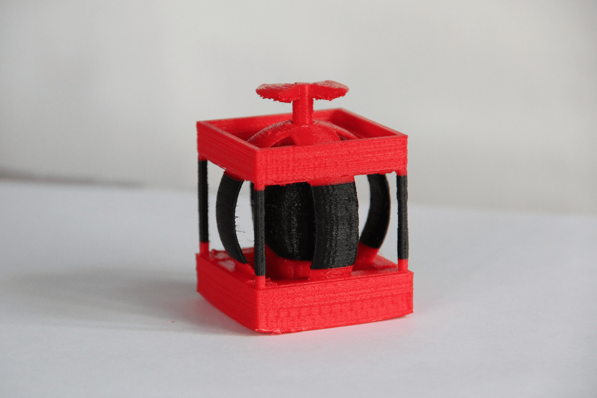
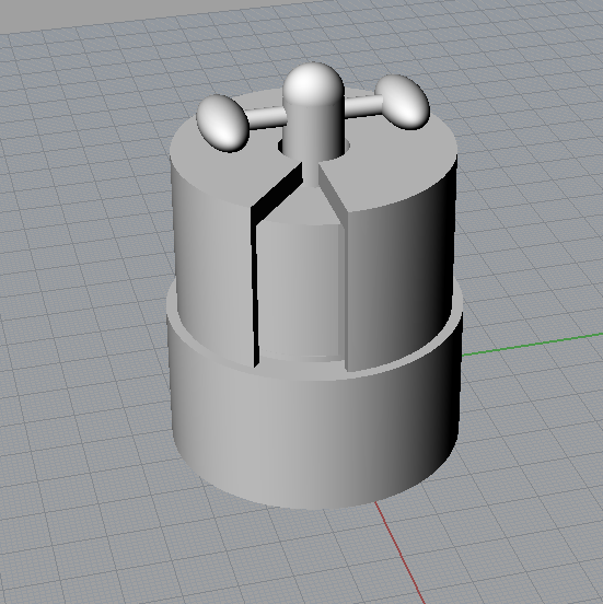
We have asked to do design and 3D print a small object which cannot be manufactured through subtractive manufacturing. I started designing in Rhinocerous with the basic shapes like circle,torus and rectangle. Actually i was planned to place a small circular sphere inside a square and diagonally placed two torus. Later i changed the design and added rotational mechanism for the central sphere, finally given a shaft on the top and a thicker shell base for the strength of its base. Finally designed my part and exported the design in to .STL(stereolithography) format for 3D printing using Ultimaker2.
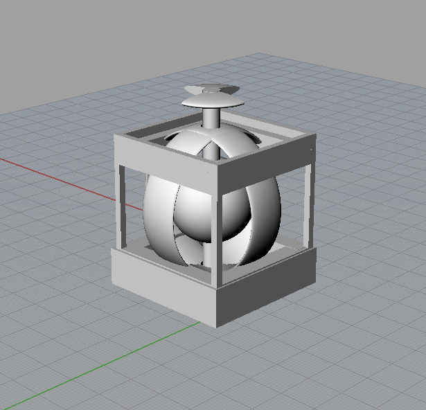
Why the design is not manufactured subtractively?
The design is not manufactured subtractively because the central shaft connected to the ball at the middle has to move freely and the two outer torus will keep the central structure from comming out of the total structure. If we are making it subtractively, then we have to make each part seperately and need to assemble it seperately.
Processing in Ultimaker
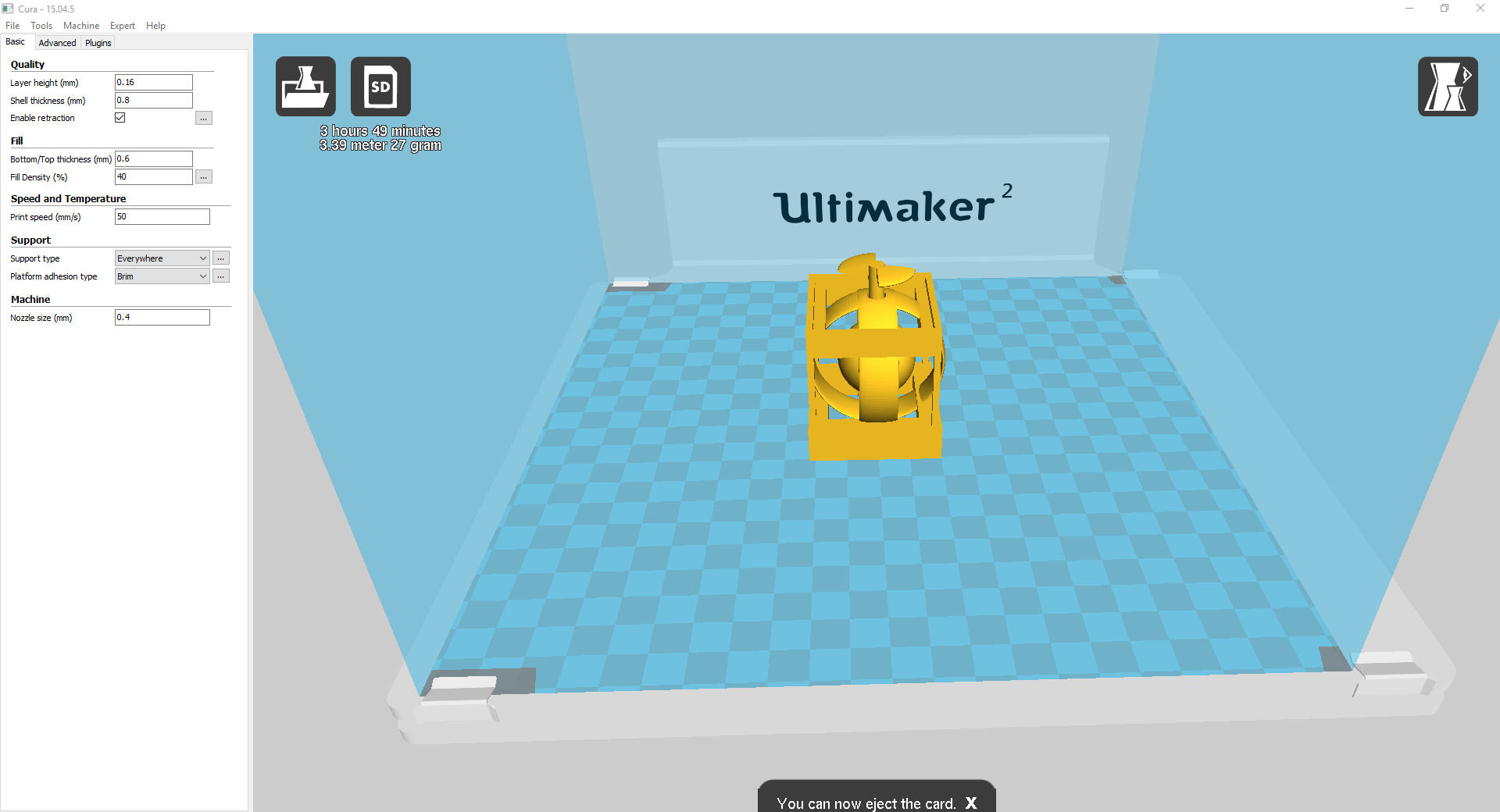
My design file was exported in .STL format and i just downloaded the Cura 15.04.5 version for slicing the design. For desigining the part i have used Rhino in my Windows office Desktop PC so i downloaded the cura software to windows PC from cura website and installed it. Before slicing the object we have to set some parameteres in cura according to this the print quality differs. Opening the design file is easy one ,you can simply drag the file in to the UI-build volume or open through the file menu in cura. Once opened we can see the object to be printed, its time and material settings on the right top corner. There are some more settings and parameters we have to set accordingly our print qulaity and other specs changes. I have given the setting as showed in the screen shots below. After setting all these parameters we can save the file called "g code" directly on the SD card through the autosave icon on the UI. Then i turned ON the Ultimaker2 3Dprinter and using the print option of the machine i selected my G code file. The steps i followed are summarised in a flow chart made using draw.io
Steps
My design part on cura software with the settings
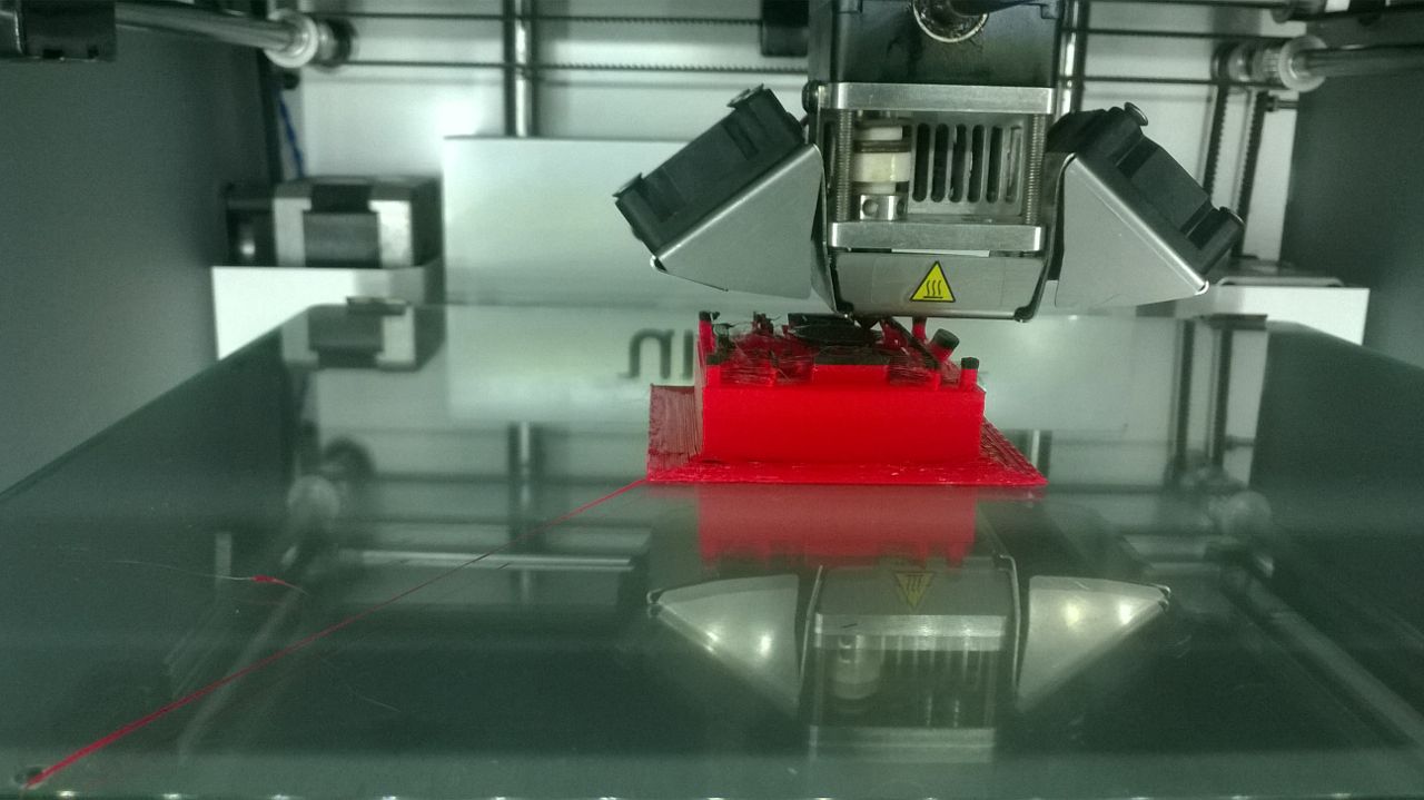
After a few minutes i observed that the print base is getting removed from the bed and severe warphage at the corners. I stopped the print and analysed about it, on further search i found that it may be due to the sticking problem of the bed or over haeting of the bed so that the edges are getting bended. Later I approached the instructors and they told in such cases it is better to put raster than brim settings for printing, In my case i have given brim option.
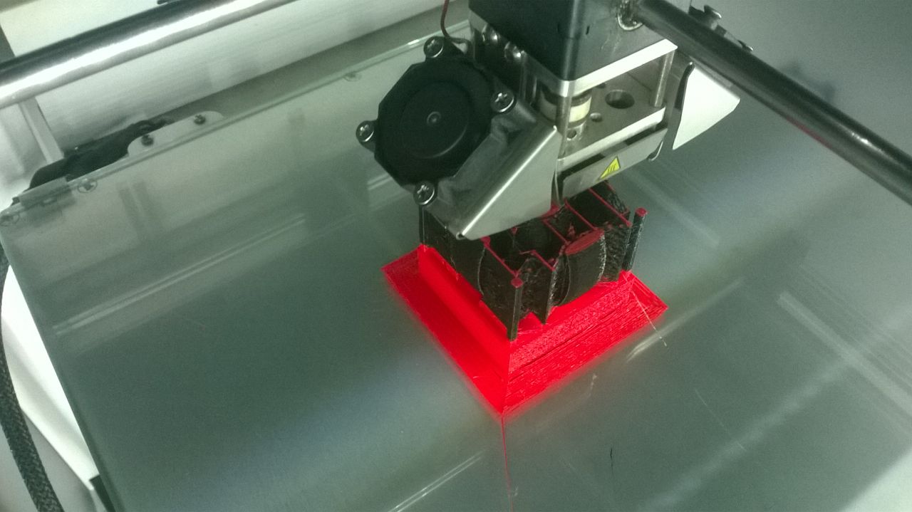
Later i have given "brim" option in cura so that one thin layer will be printed around the print. Also for sticking the part on the bed just tapped the surface of the glass with transparent tape and removed it so that better glueing will be there. It took less than 4:00 Hours to finish my printing. Here i tested multicolor print also, In Ultimaker 2 we don't have dual extruders, for doing multicolored prints we need two extruders here i manually paused the print in between and changed the material and continued the printing. It has to be done very carefully otherwise our entire print may fail. Initially I started with Red PLA and in between used Black PLA and again used Red PLA for printing the top portions.
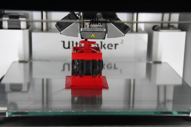
These are some of the shots of my 3D print. The first one is the starting of black color printing amd the second one is the top red color print.
After the print i carefully removed the support materials using the knief and tweezer and got my finished part. At the time of slicing i noticed the amount of material(PLA) required for
the print and showed 27 grams you can see it in my screen shot. Actually i safely removed and kept all the support material i removed and i checked the weight of the whole
part using the digital weighting machine and it showed 22.9 grams. So, Nearly 4 grams is vasted as vapor and lossed while removing
Next i checked the shaft area near top and bottom top area was clear but the bottom area clearense was poor. The problem was i have given the bottom shaft length a little
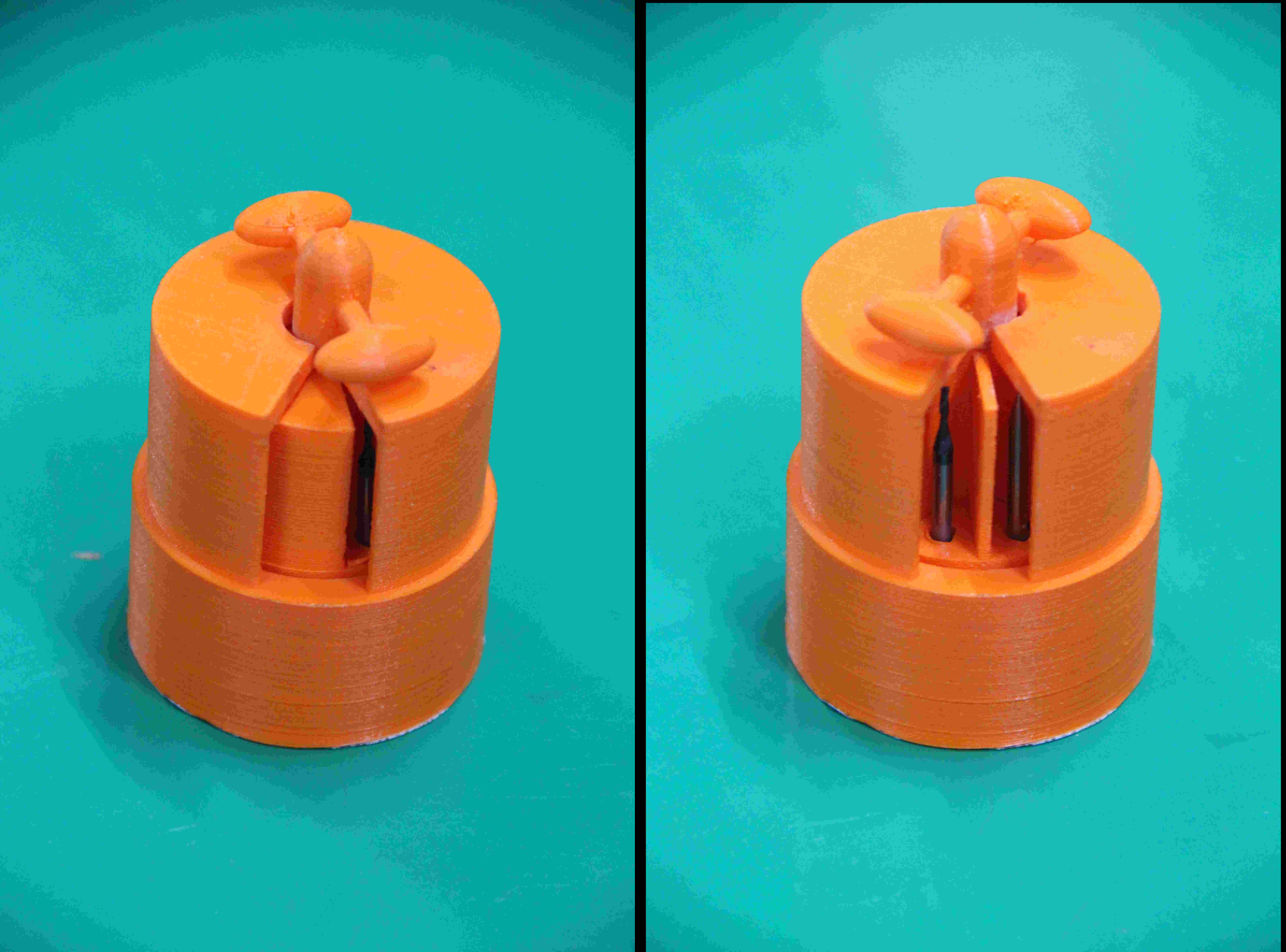
bit smaller than the outer wall so there some support material filled the gap. Inorder to solve this issue cleaned the bottom area and my shaft started rotating. The hero shot of my
model is shown below. You can still see some warphage problems at the corners of the print. The rotation of the part is shooted in my phone and added to youtube. For identifying the rotation, Placed small pieces of vinyl sheets with red,yellow and blue color. You can see
the video here. 3D scanning is a technique to capture the shape of an object using a 3D scanner. The result is a 3D file of the object on a computer.
Many different technologies can be used to 3D scan objects, environments and people; each technology comes with its own limitations, advantages and costs.
The basic principle is to use a 3D scanner to collect data about a subject. The subject can be an object, an environment or even people. Some 3D scanner can collect simultaneously
shape and color data which can be saved, edited, and even 3D printed. 3D scanners are powerful tools for professionals in several industries, such as automotive, aeronautics, dental,
jewelry, video games, special effects and animation movies. Different 3D scanning methods used are listed below. The detailed description about each is available in this link
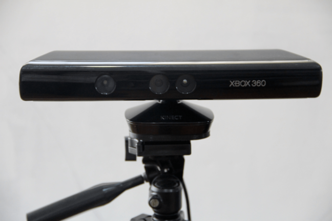
3D Scanners in our Lab We have Kinect Xbox360, Intel Real sense F200 camera and Modela Machine available for Scanning. Kinect is a hands-free motion control device by Microsoft for Xbox 360. It allows players to control games using a combination of
body movement and spoken commands without having to hold a controller in their hands. The Kinect sensor had a horizontal bar, built into the bar is an RGB camera, a multi-array microphone, and a depth sensor.
These three elements combined allow the Kinect to perform 3D motion capture and facial and voice recognition. The depth sensor consists of an infrared projector and a sensor. The projector projects a continuous infrared pattern over its field of vision, which the sensor uses to interpret the scene.
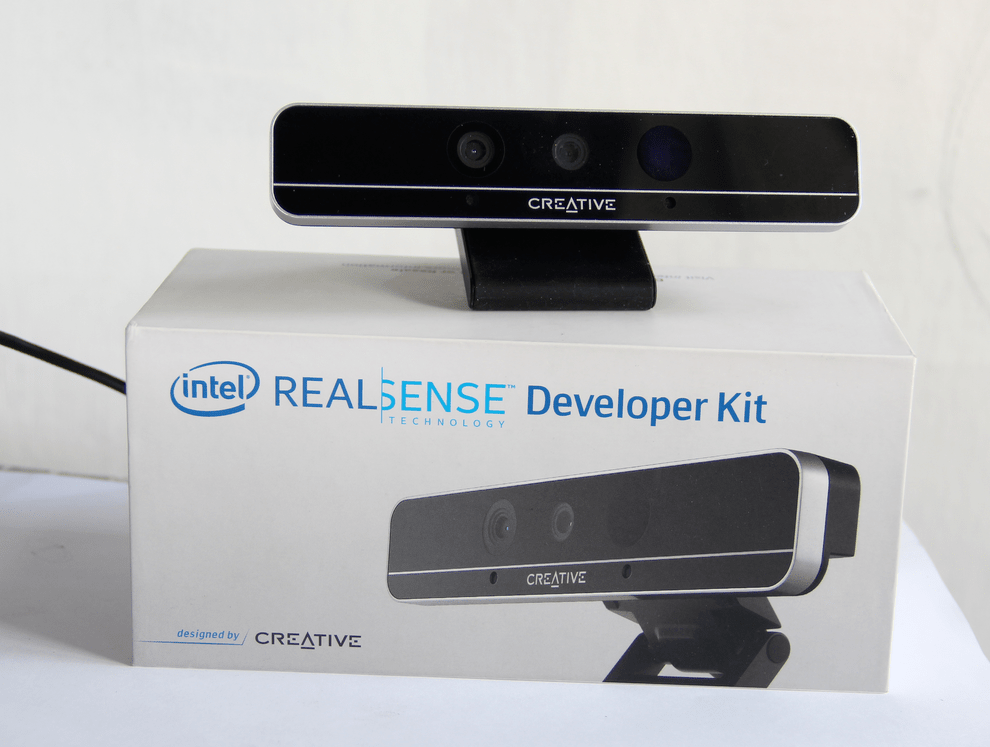
Facial, voice, and motion recognition is handled by Microsoft's Kinect software. To Know more Intel RealSense, formerly known as Intel Perceptual Computing is a platform for implementing gesture-based human-computer interaction techniques.
It consists of series of consumer grade 3D cameras together with an easy to use machine perception library that simplifies supporting the cameras for third-party software developers.
We have Intel Real sense F200 3D camera and it contains the following four components: a conventional camera, an infrared laser projector, an infrared camera, and a microphone array.
It is intended to be used for natural gesture-based interaction, face recognition, immersive, video conferencing and collaboration, gaming and learning and 3D scanning. Setup Requirements F200 camera shall be connected to PC using USB3 port – OS does not detect camera connected via USB2. Other requirements include 64-bit Windows 8.1 and Intel processor with SSE4.2 instruction set support.
It is recommended to use 4th generation of Core processors, but at least some of the 2nd and 3rd generation processors in combination with RealSense SDK ver4 are capable to support F200. I started this part by installing the Intel real sense drivers and SDK befrore starting the scanning. You can go to the link given for the installation steps. First insatlled the driver for F200 camera and then installed the 3D scan component from the SDK in my office dell optiplex3020 desktop. Everything is installed correctly
and connectd the camera and it got detected. Then i followed these steps
for the scanning , but in between my camera got disconnecting and scanning is failed i repeated many times and the same issue persists. I feel some connection issues with the camera, so i skipped the scanning with this camera. To enable using Kinect on Windows for scanning purposes we need to first install the drivers. The easiest way is to do it one shot is to install the Kinect SDK from Microsoft Skanect is an application software for scanning by Occipital. It is an fast ,easy software which can capture full 3D colour of an object and process it. We can download
the non commercial version software for free from the site. Installed the software in laptops and ready for the scan. First we have to set the scanner in a right position so that it won't move
and is under the range. Here we set the sensor constant and the set the object to move. I was the first object for this scan, we had used a rotating chair for easy rotation.
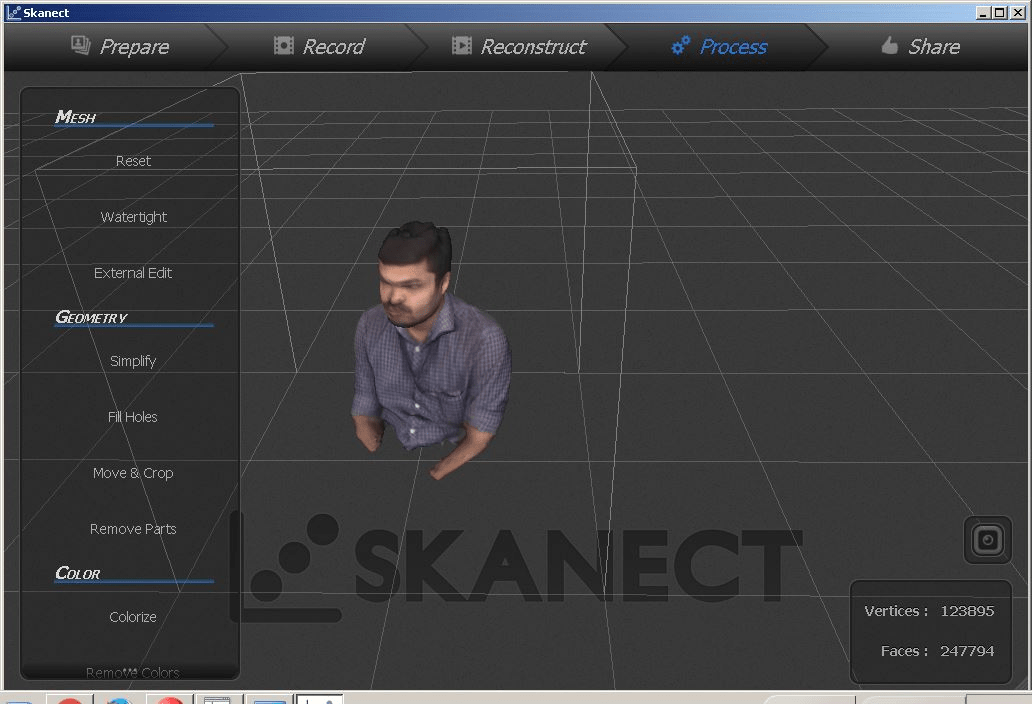
Open the Skanect, Make a new project with appropriate setings with the "prepare" menu . Next move to record menu ,you can see the bounding box appears and we need to check that the object is
inside the bounding box. Once fixed we can start the scanning by pressing the record button on the extreme right corner with round inside a squre. Then we need to Move slowly around the object until you have
managed to capture all the data we want. Then stop the scanning by pressing the record button again. If the scan becomes misaligned, just need to line up the black and white image overlay with the physical data until it snaps back.
Sometimes, we may have to take multiple scans to get everything. We had tried the scanning by moving the sensor around the object but didn't worked well. After completing the above steps move to the reconstruction and post processing steps, from there you can process the data. After all porcessing and colorising my scan came
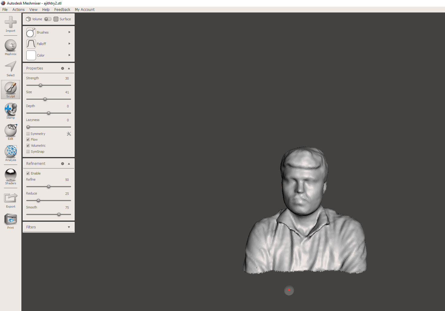
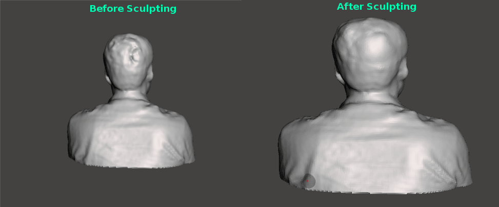
in the Skancet as showed above. Next we can export the model in PLY,OBJ,STL,VRML formats. I had exported it in .stl format , next for editing the file installed Meshmixer
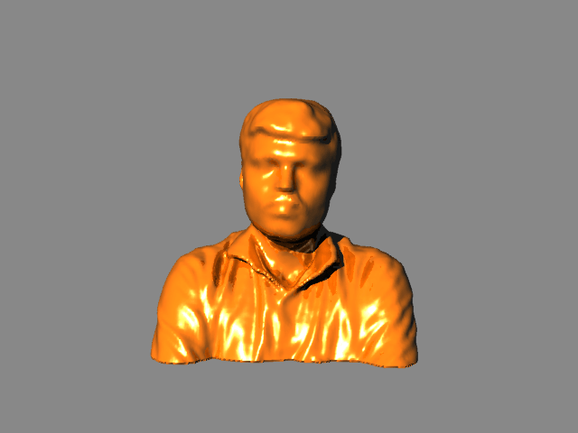
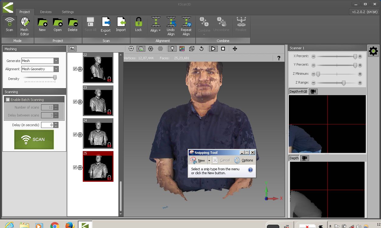
software and done sculpting on the back of the head to remove hole from the default skanect reconstruction. This is the after effect of editing with mesh mixer Finally uploaded it into rhinoceros and rendered it as showed below. The design was uploaded in Sketchfab and rendered properly as showed below. Kscan3D is another software for scanning.Kscan3D is a Free to use program, which is the Scanner front End for the Kinect and similar sensors.
We need to Capture data from multiple angles to create a complete 360 degree mesh. KScan3D can capture and align 3D meshes automatically. Once the data is captured,
we can also use KScan3D to edit or delete un wanted points, smooth data, etc. We can export final meshes in .fbx, .obj, .stl, .ply, and .asc formats from the Kscan software.
This time i scanned Jim using Kscan. It is similar to Skanect but it doesn't having the ability to make water tight models on its own,
so we need to do some post processing in a mesh editing tool. The main thing to notice is that if we install multiple softwares in a single PC sometimes it won't work, so we have
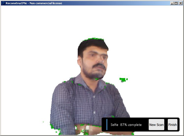
to uninstall the others to opearte successfully.The screeshot of the scan is shown below. ReconstructMe is one stop application for for real-time 3D reconstruction. It is simple to install, easy to use and allows you digitize objects by simply moving your sensor around them.
The installation and scanning steps are easy there are lot of references available on how to do the scanning properly. You can follow these steps available in instructables.
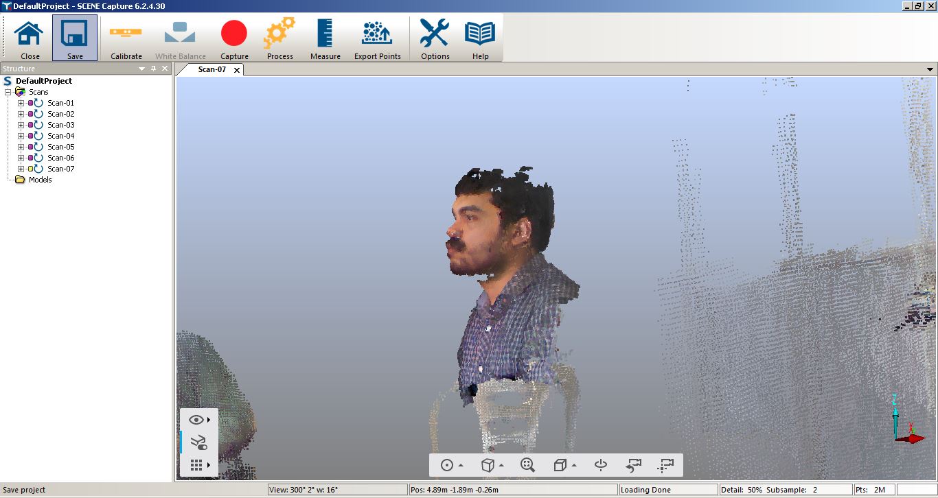
We sat on the rotating chair and moved but didn't worked properly. Screen shots are shown below. SCENE Capture is the application used by FARO to drive the FARO Freestyle3D sensors. In Addition, other 3D sensors are supported as well.
The main task of SCENE Capture is the registration of single 3D frames to compose larger sceneries. Objects can be scanned from different sides by moving the sensor around the objects and rooms by panning and moving the sensor inside the rooms.
Even though more information was captured using this tool, like multitude of points and their co-ordinates, colours etc. All our scans were done using Jims laptop, the scanned datas are heavy in size and was exporting it
in IGS and DXF formats. From all of these expirimentations we concluded that this is one of the powerfull software that can be used for proffessional use. You can see the below screen shot in that the scanned portion is clear than the other softwares. The main limitation in 3D scanning is the hardware we are using, if you have a portable high end scanner we will get a detailed resolution scans .We have
the kinect sensor and the Intel Real sense in our lab. From my experience using them, I can say that the kinect is not suitable for small fine details, it is good for large long range objects like furniture and rooms.
It has very poor resolution. I have limited experience with Intel Real Sense, since was not able to get it working in my PC, I can say that it is not suitable for long range scanning. This week i actually planned to make a small closed box for keeping the PCB Milling bits. These bits are very fine and having small dimensions, we are keeping it over the modela machine
in a 3D printed box. Inorder to prevent it from the physical damages i planned to make this box, in which the bits will be kept inside a cover. I started the design using Rhinoceros for small test pieces
inorder to make the box rotating. Made a small test object for testing the tolerance and other parameters given a tolerance of 2mm inside the channel for the smooth rotation. The design is showed below
After printing in ultimaker i got the part but in some places the material was fused a little bit and it was not moving freely. I just drilled a hole this time it moved freely. Accordingly i made the full design
of Modela Box in Rhinoceros. My modela bit box design screen shot are shown below. This is also a non subtractive model because you cannot remove the parts seperately but the two parts will rotate, One of the limitation is the clearence to keep the bits on the slots
which is very small in this design. The hero shot of my modela bit box and working video are given below. Working video of Modela bit box Download My Modela bit box files (Google drive) This is my third practice in designing, While searching different 3D models i found a text display like the one i made. Inspired from the design i made this
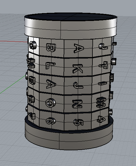
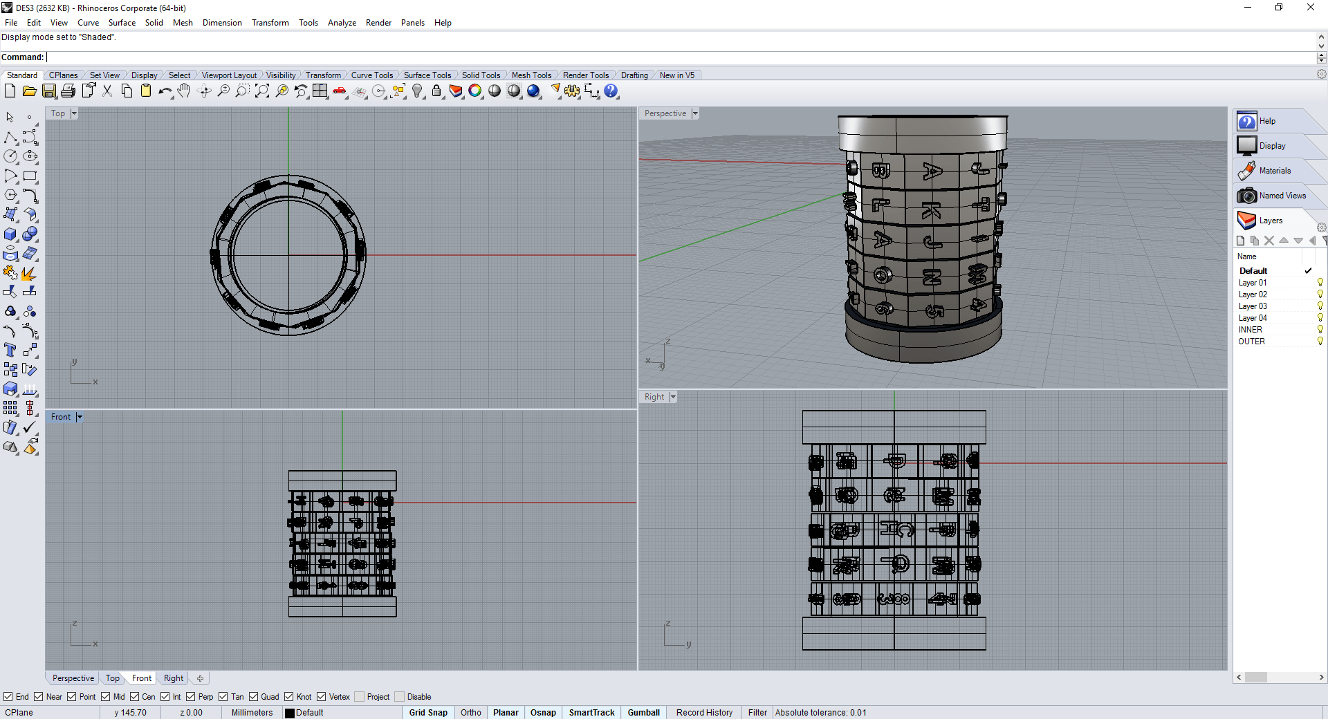
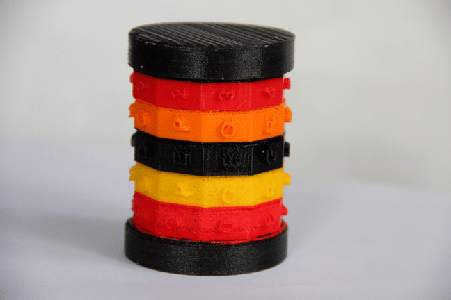
text display. This is simple in looking but it takes nearly 4:00 hours for me to design this in Rhinoceros. The inner core desin and the ring designs were done esily. The complex part was
to place the text and arranging it in the proper way. It is another non subtractive design, as these rings can't be seperated and can rotate individually. First i designed the individual rings and placed the texts with a height of 4mm and placed one by one total 10 phases are there in one ring.
The total display contains 5 rings in which two of them are same but placed alternately, contains english alphabets from A,B..up to T, the third one contains numbers from 0 to 9.
Completed the rings and arranged them in the the outer shell with 0.5mm gap between them. Final look is shown below. Finally printed in Ultimaker.This time also i have tried the multicolored print, given minumum settings in cura, for each rings i have given different colors
some PLA didn't extrude correctly may be due to some corrotion inside the nozzle,so the rings printed in different qualities. The print was completed in 5:30 Hours, the individual rings get fused
because i have not given the support structure before printing, using a knief i seperated the individual rings. Finally it worked the hero shot and working video are shown below. Download My test display files (Google drive) "Talk to yourself in a day , otherwise you may miss meeting an excellent person in this world"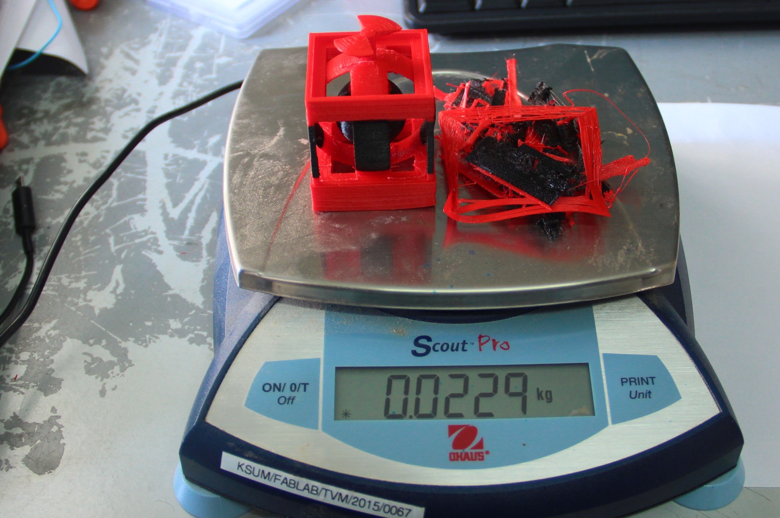
II. 3D Scanning
I. Kinect Xbox-360
II. Intel Real sense Developer Kit
3D Scanning Part
Scanning with Real sense F200
Scanning with Kinect Xbox360
Scanning with Kscan3D
Scanning with ReconstructMe
Scanning with SCENE Capture
Limitation of 3D scanning
Extra Assignment
I. Modela Bit Box
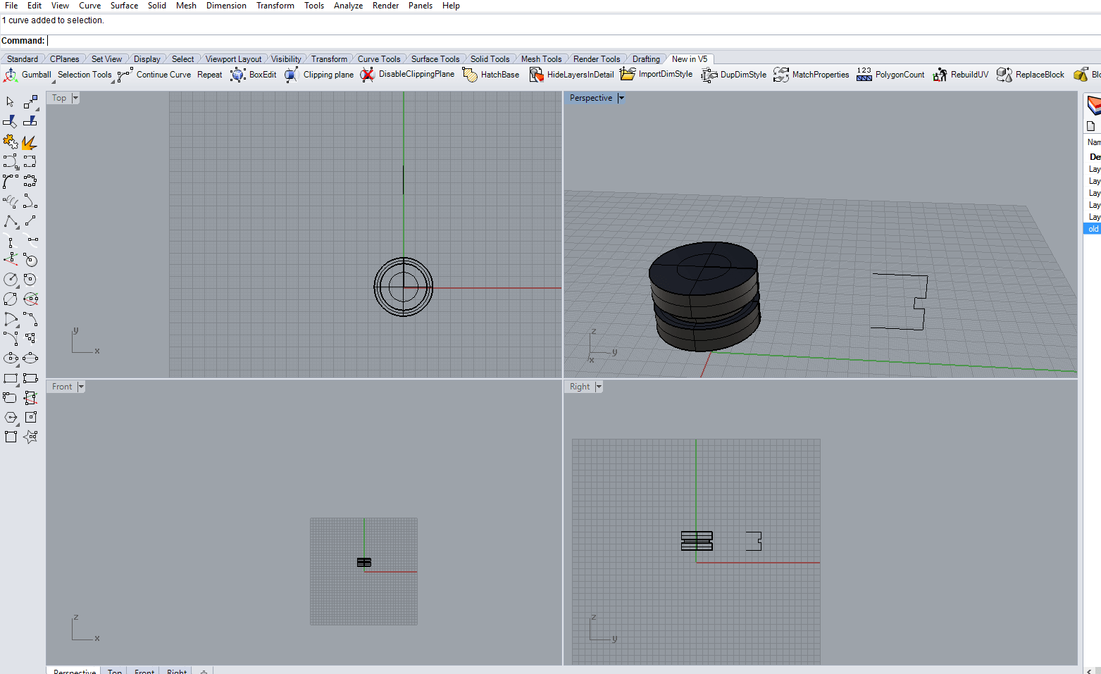

II. Text dispaly
Quote of the Week