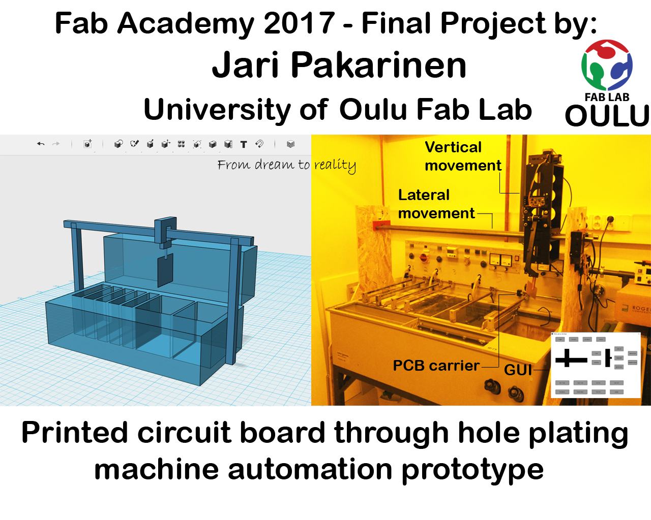
Final Project - Through-hole plating machine automation
What will it do?
My final project is automation of PCB through-hole plating machine. Currently one must be involved in the process and move the blank pcb by hand as it goes through 5 separate process phases. To make it automated would let the pcb manufacturer concentrate on other tasks while the through hole plating system would take care of itself.
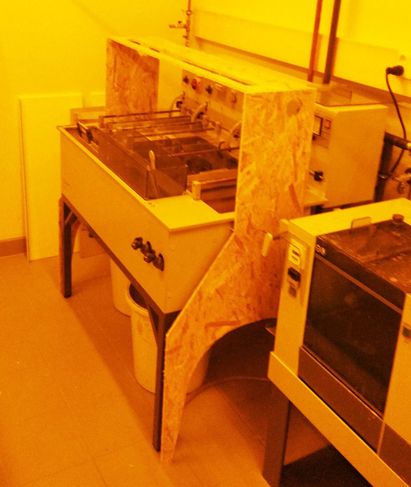
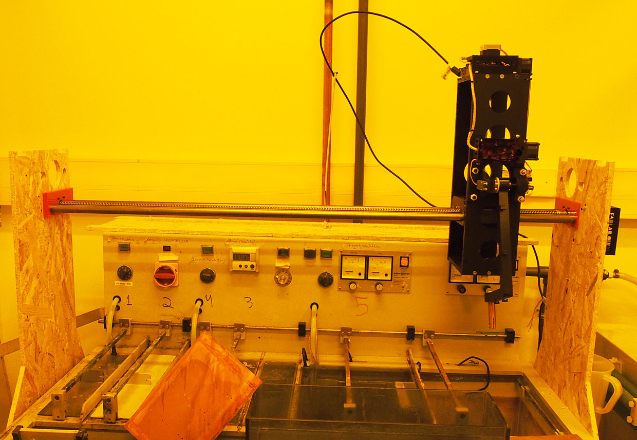
The through-hole plating machine
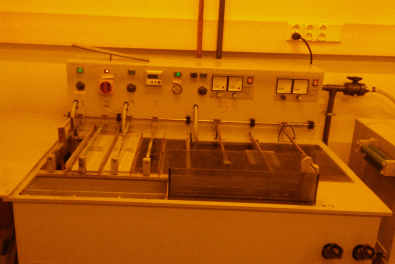
The through-hole plating machine at our university PCB manufacturing line. It is all manual, but will be automated after fab academy 2017.
On the original machine there are seven tanks. Five small ones and two big ones. Of those four small ones and one big one is in use. While in process the blank pcb goes through tanks in sequence and must be rinsed between tanks. See the process flow on the picture.
Sketching the project through spring
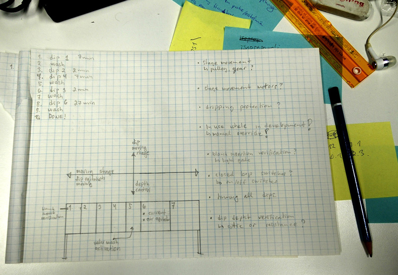
To make this happen, I will need to add a mechanical moving mecanism to get the plank through the process. Recuirements are:
1. Plank has to move sideways and stop on correct bath position in correct order for correct time period.
2. It has to have up and down movement to dip the plank to the bath. Every bath will have specific "swim" time which have to be achieved.
3. In some baths the plack has to be agitated, i.e. moved back and forth, so moving mechanism has to be added to the plank attachment point. Or by using the main moving unit.
4. In some baths the liquid level might not be optimal every time, so it would be really nice to have some sort of level indicator on the plank attachment arm to control the dipping depth.
5. On some baths electrical current and air activation switches must be added.
6. Between most of the baths, the plank must be rinsed with water spray. So this must be included to the movement of the plank through the process.
7. Closed loop monitoring of the plank movement would be good.
8. It is critical that the process is usable while building this automation as pcb manufacturing happens daily at the university!
I am hoping to get most of the separate sub modules done during the different subjects studiet at fab academy. At least the following sub modules might be possible:
1. General mechanics.
2. Liquid level indication, either optical or resistance or something else...
3. Water rinse, electric current activation, closed loop monitoring and plank insertion proving.
4. Main stage moving and dipping motors and control.
5. Timing?
After week 2 assignment
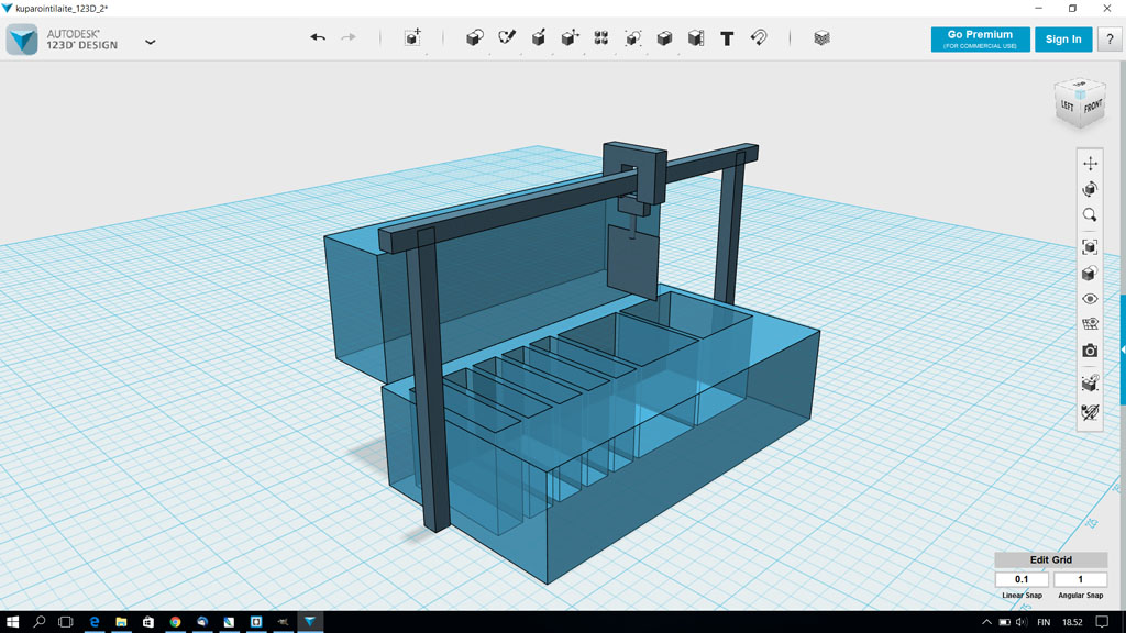
After week 2 assignments here are couple of sketches made with 2D and 3D tools used. You can find them on week 2 assingment page as well.
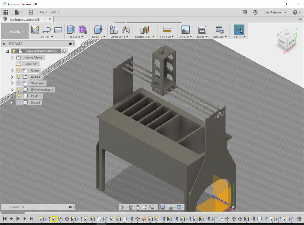
Here is the 123D file showing general overview of pcb through-hole plating machine with sketched blank moving structure. For the source file: Kuparointilaite_123D.123dx
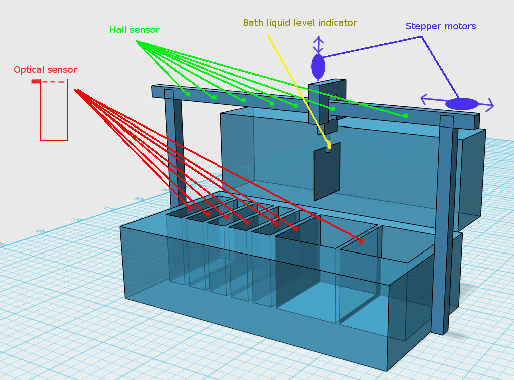
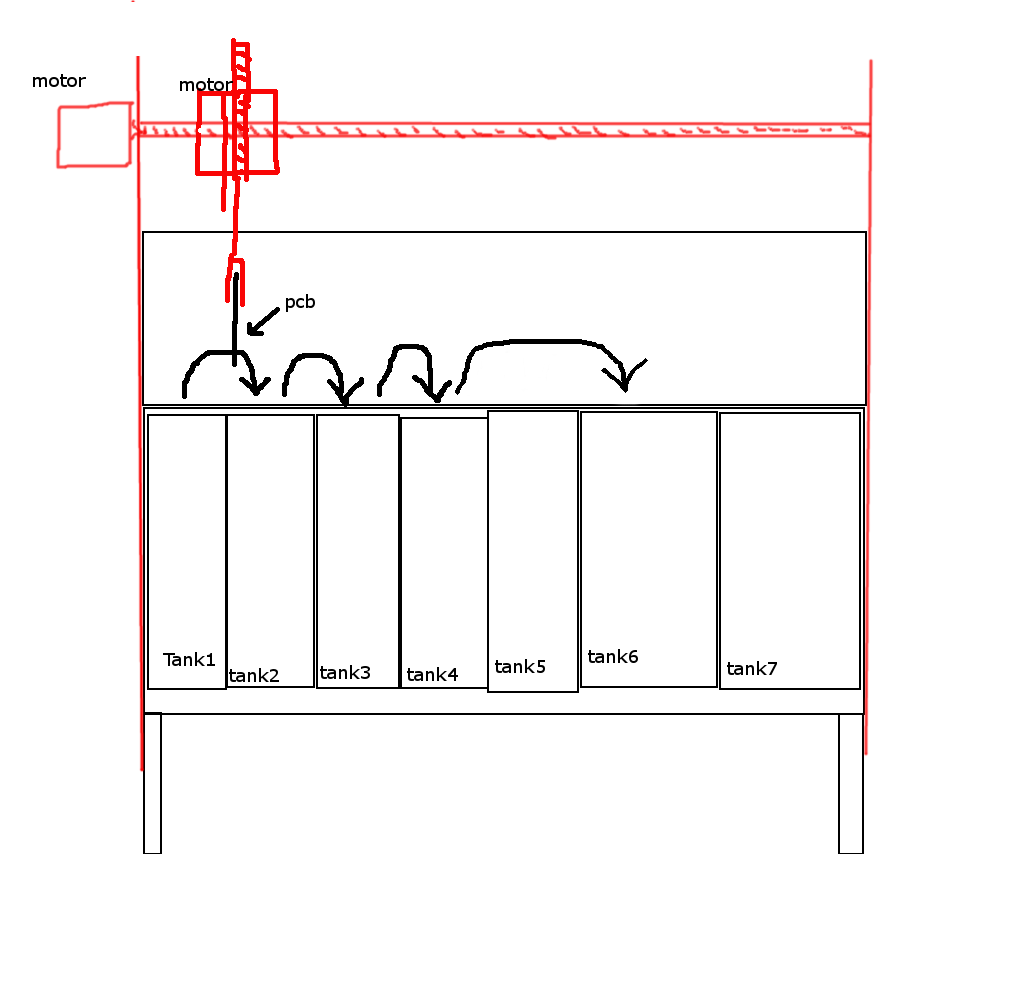
Here is the gimp image showing sensors and motors needed for the system in generalized view. For the source file: 123D-hahmotelma_gimp.jpg

Here is the FreeCAD file showing the current blank holder and two of the smaller tanks where the blank must be bathed. Levyteline2_FreeCAD.FCStd
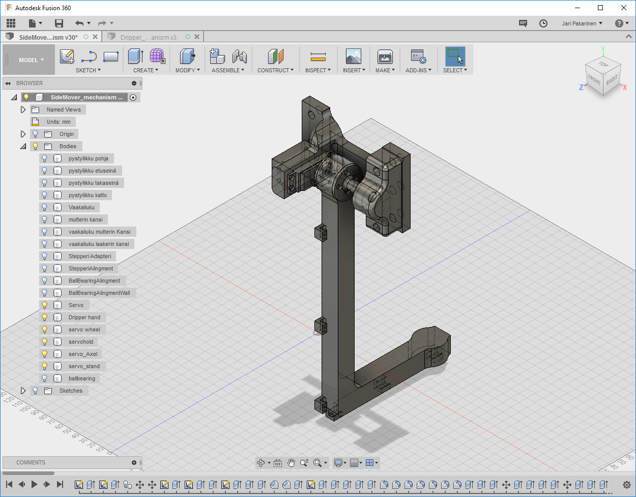
As the design got better and better I made new designs of the parts on fusion. Here is an overview picture. Rest of the final designs can be seen later on this page. As it will be explained later on the page, all mechanics design were done with Fusion 360.
Through hole plater machine .f3d file from Fusion 360
At this point Fab Academy was almost through and it was time to start working on final project. Until this point designs were sketches and now it was time to start the actual desing in its final form. These last two pictures were already of the final design.
Manufacturing mechanics
Finally I designed the actual parts for the machine. First I did the moving parts and the slides and structures for motors and screws. All design was done in Fusion 360. Manufacturing was made using 3D-printer and Large 2.5D-milling machine Rensi E2-1325. Designing in Fusion 360 is explained in week 5, week 7 and week 12. 3D-printing is explained on week 5. Using our big milling machine Rensi E2-1325 is explained on week 7.
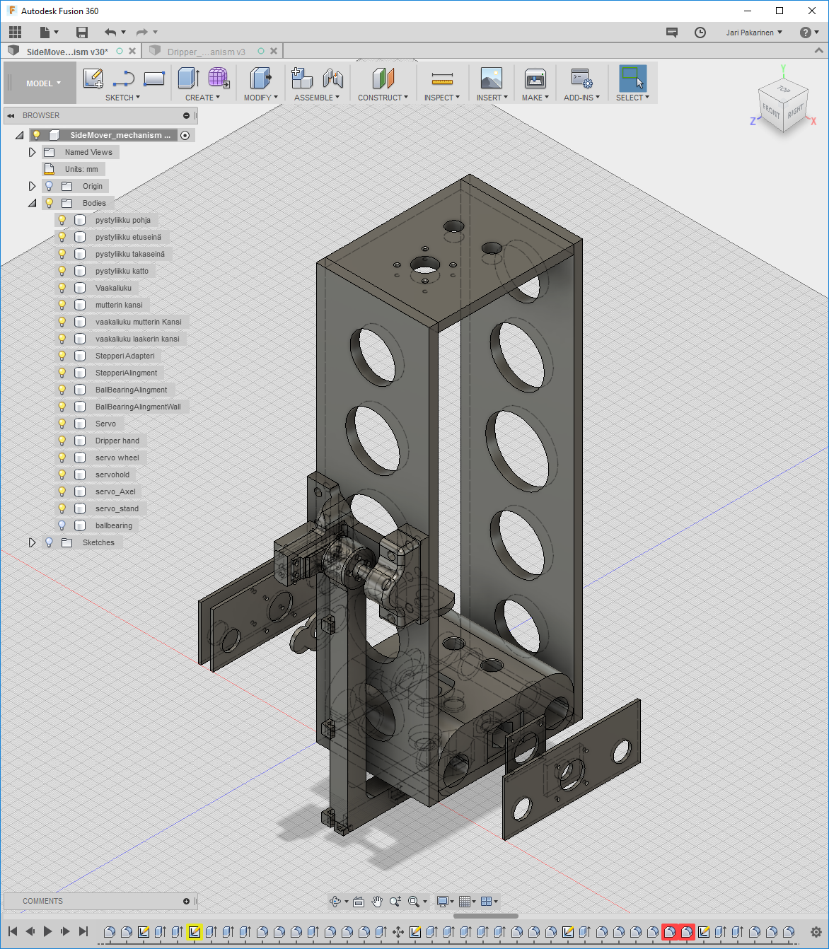
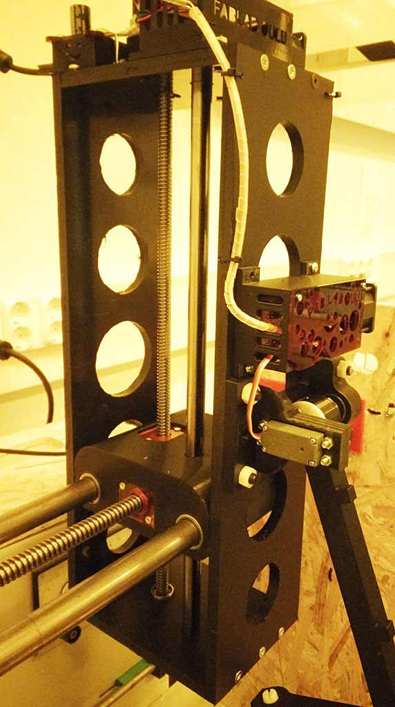
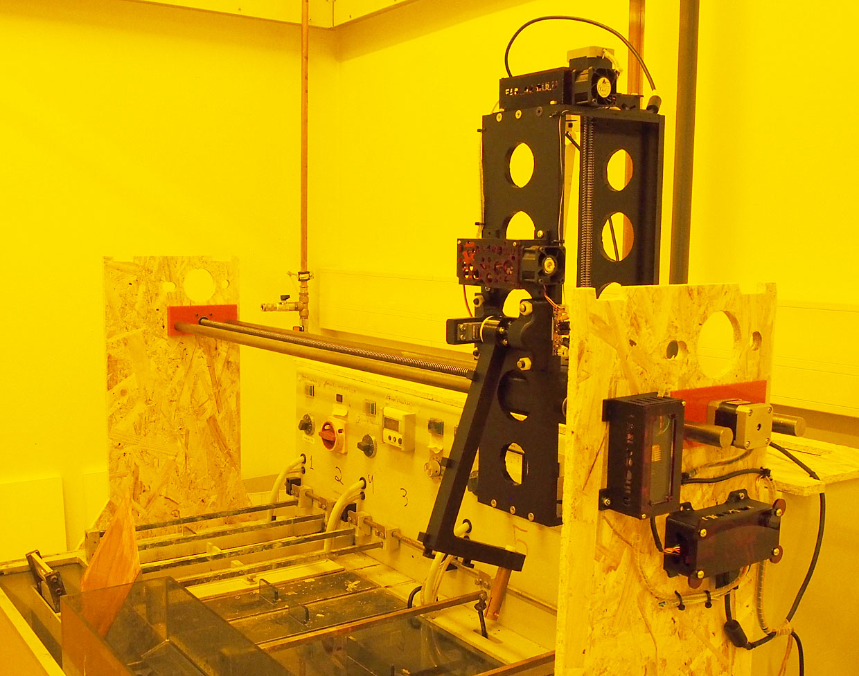
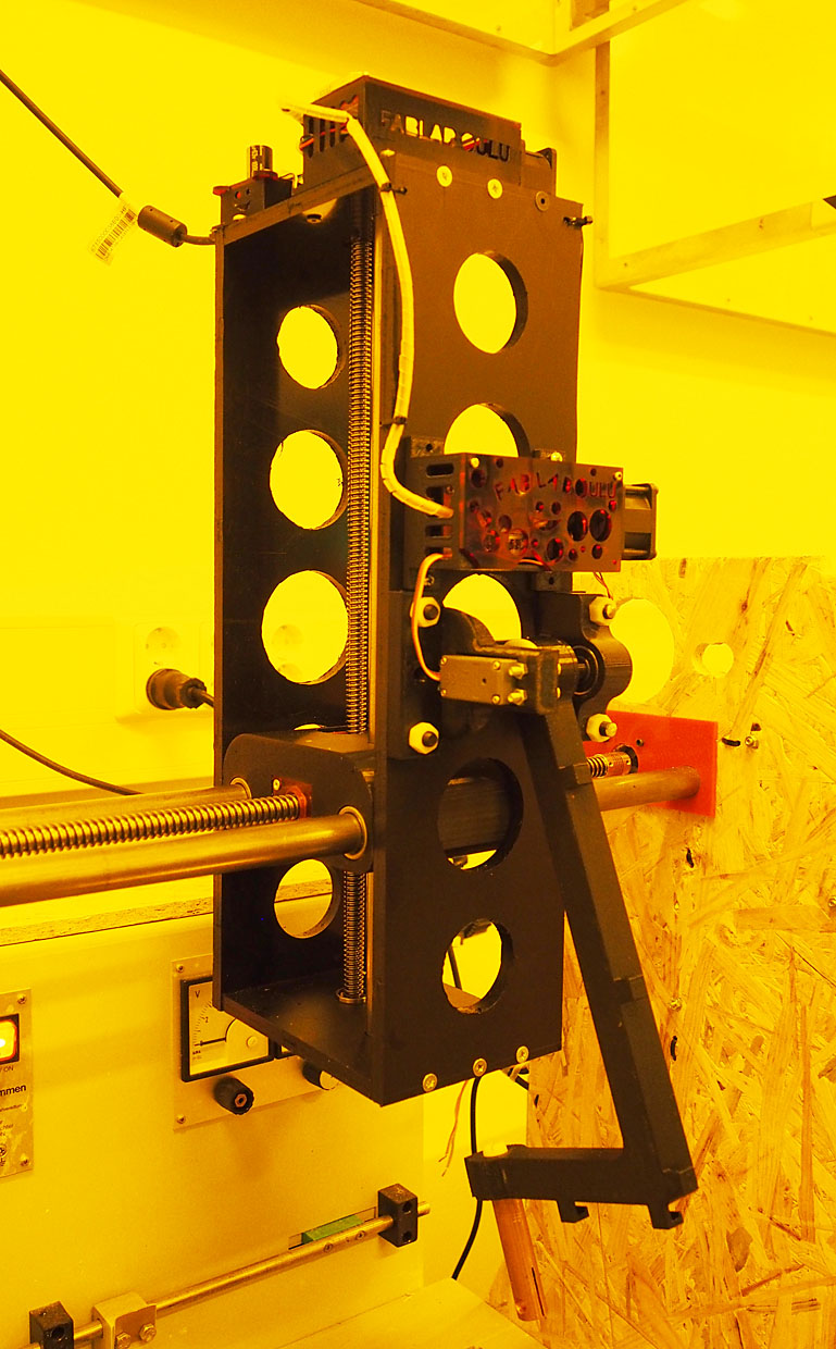
Vertical and lateral mover unit building and assembly
Building vertical and lateral mover units. Here is a Fusion 360 picture of it. For more detailed description of the building see the additional page here. I moved to other page so that the main final project page would not be too long.
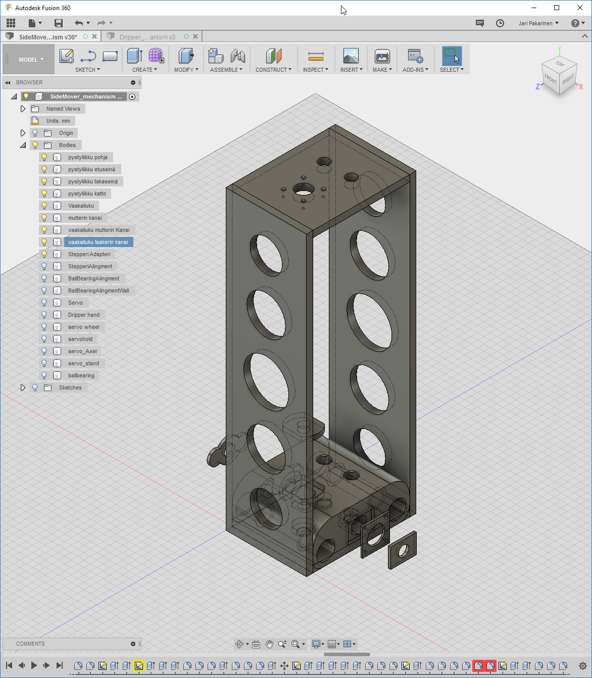
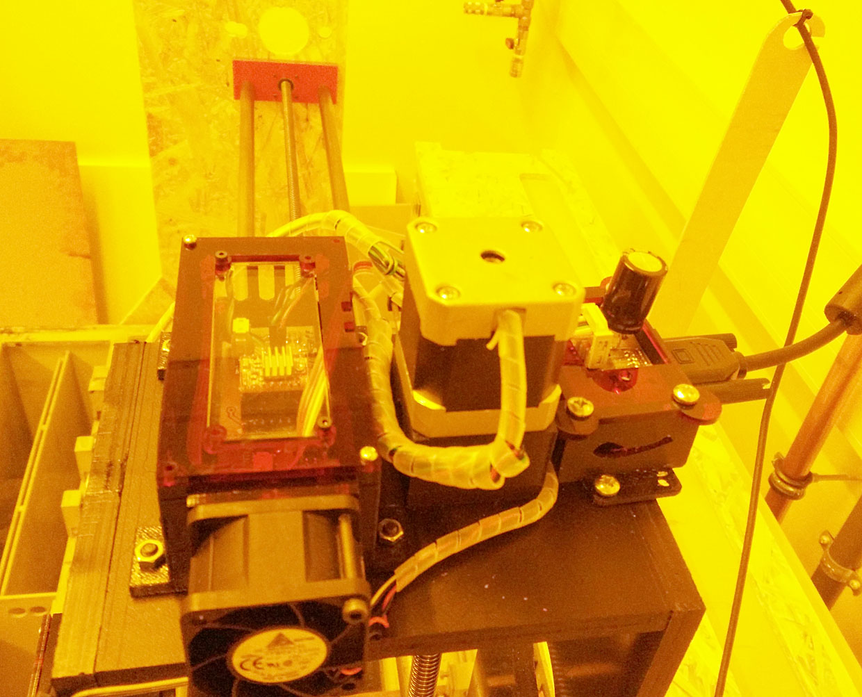
Here is the final assemply with all components on it.
Main lateral slide block .stl file
Main lateral slide block nut cover .stl file
Main lateral slide block ball bearing cover .stl file
Main lateral slide block vertical nut cover .stl file
Main lateral slide covers laser cut .pdf file
Main vertical slide parts mill files .nc file
Main vertical slide parts mockup laser cut .pdf file
Main lateral move unit .f3d file
Side walls
Structure support walls were made out of wood at something big week, week 7. They were used as made at that time.
The top part of the week 7 model was not used at the end but the side walls worked fine for the assemply.
Wall .stm file with CAM from Fusion 360. Other files are available on week 7 page.
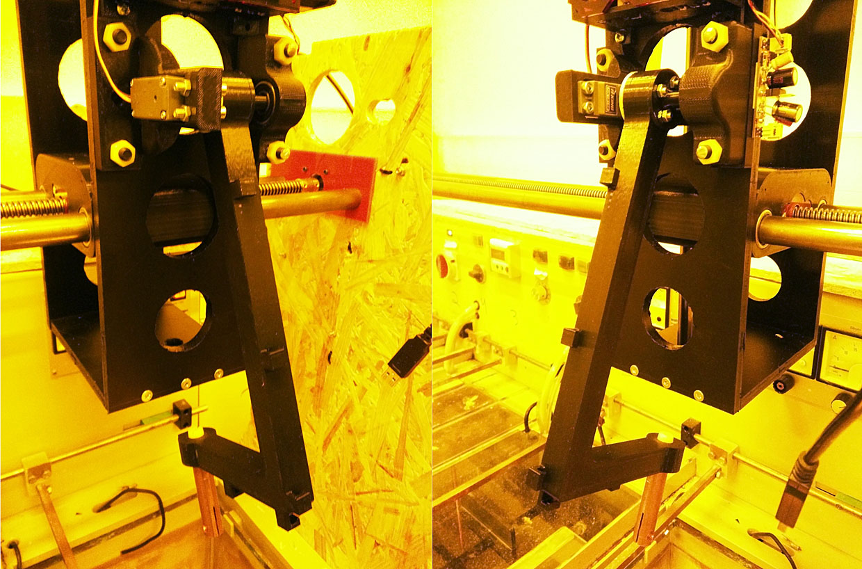
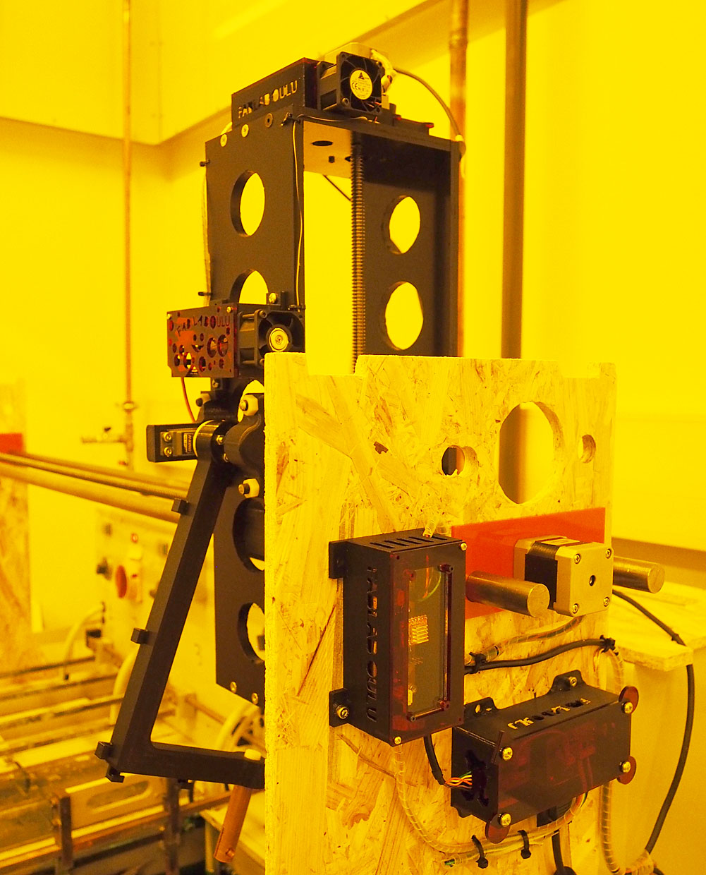
Servo arm and it's electronics
One main component was not done during earlier weeks but during the last two week when working on final project alone. It was the servo arm that holds the pcb. It includes three parts, the servo, mechanics and servo controlling electronics.
Mechanics
Servo was a Fab Lab stock item. The mechanics were designed using Fusion 360 program and printed with 3D printer. Using Fusion 360 is explained at week 7, week 5, and on week 12. Printing with 3D-printers is explained on week 5.
I have designed the whole moving assemply as one set. As such the .stl file file from Fusion 360 includes whole assemply. On the picture only the servo arm assemply is visible. For printing with 3D-printer all parts have to be exported as single .stl files.
Dripper hand .stl file from Fusion 360Servo stand .stl file from Fusion 360
Servo hold .stl file from Fusion 360
Servo axel .stl file from Fusion 3600
Full mover assemply .smt from Fusion 360
Full mover assemply .f3d file from Fusion 360
Electronics
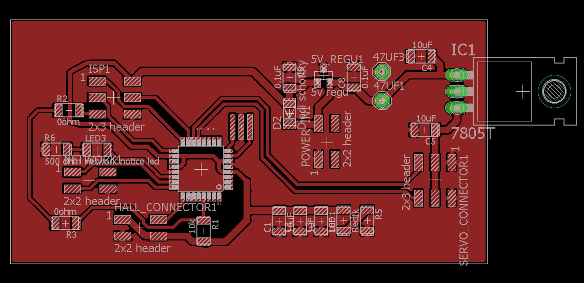
Controlling the servo, I designed a servo controlling board. Electronics design and manufacturing is explained on week 4 and week 6. Programming enbedded systems is explained on week 8.
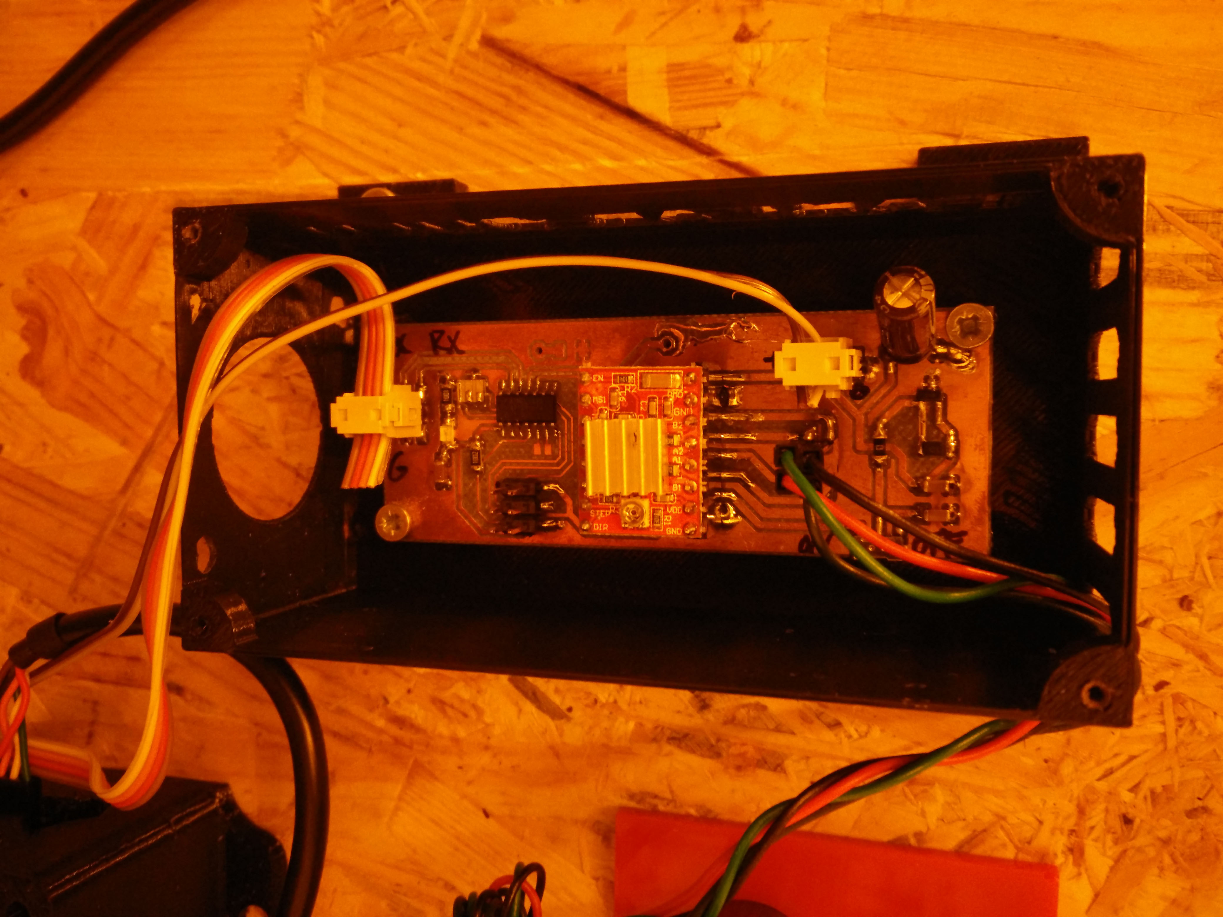
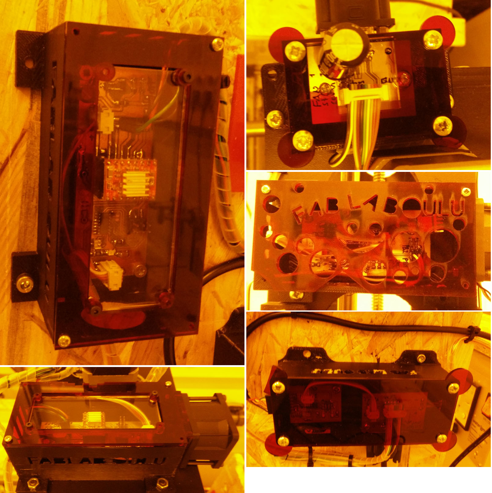
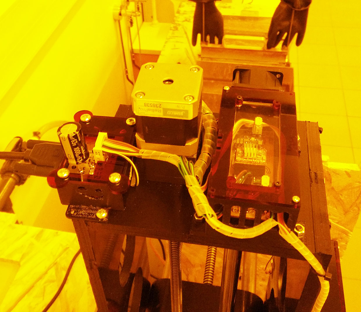
Here is the board in it's place in machine. One Capasitor is added afterwards. It is not on the eagle design.
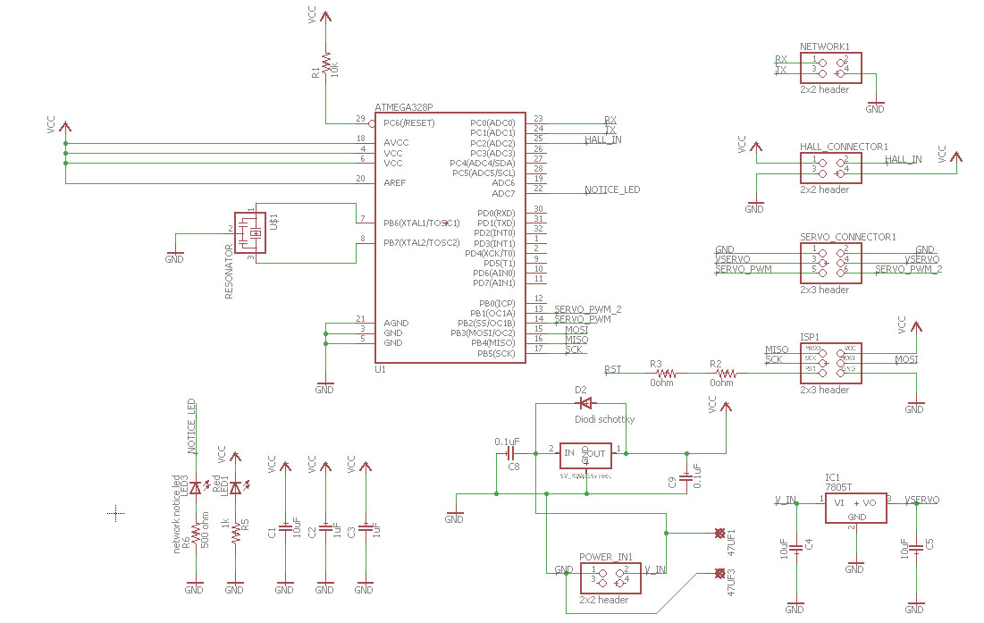
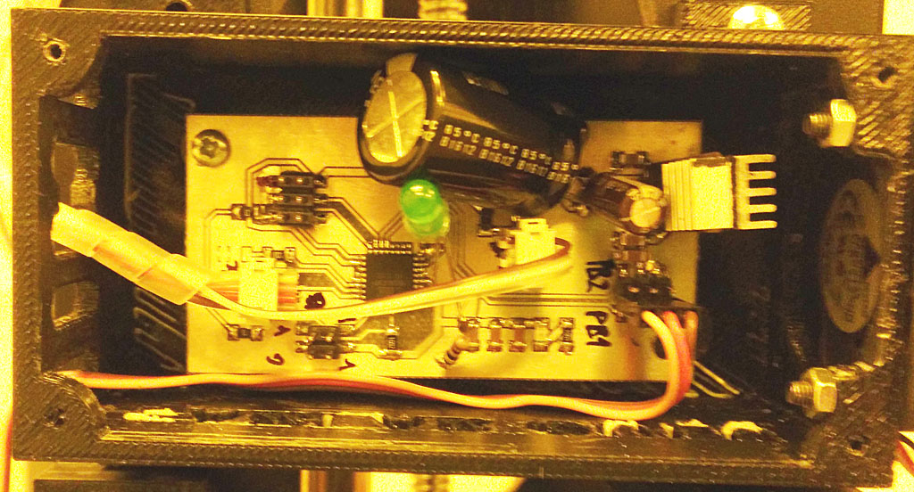
Programming of the board was done with Arduino environment. See sources above at Programming part.
Eagle schematic fileEagle board file
Eagle exported top gerber file
Eagle exported outline gerber file
Eagle exported drill gerber file
Arduino code file .ino for servo board
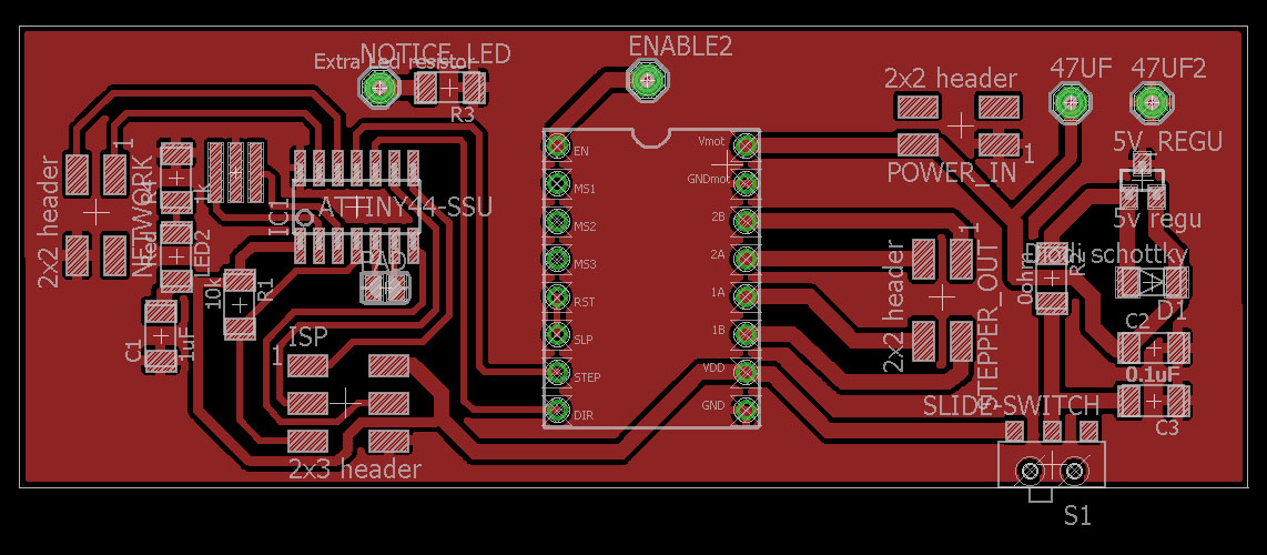
Stepper motor controller board
For the final project I designed a stepper motor controller. The first version was done at week 10. After that I modified the board on week 15 (Networking and Communication) and added a network to it. After that I made one more version of the the board. For this final version I added some capasitors to even any spikes coming from power supply.
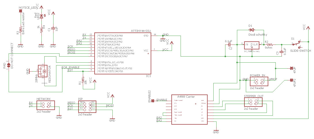
Eagle schematic file
Eagle board file
Eagle exported gerber .top file
Eagle exported gerber .out file
Eagle exported gerber .drd file
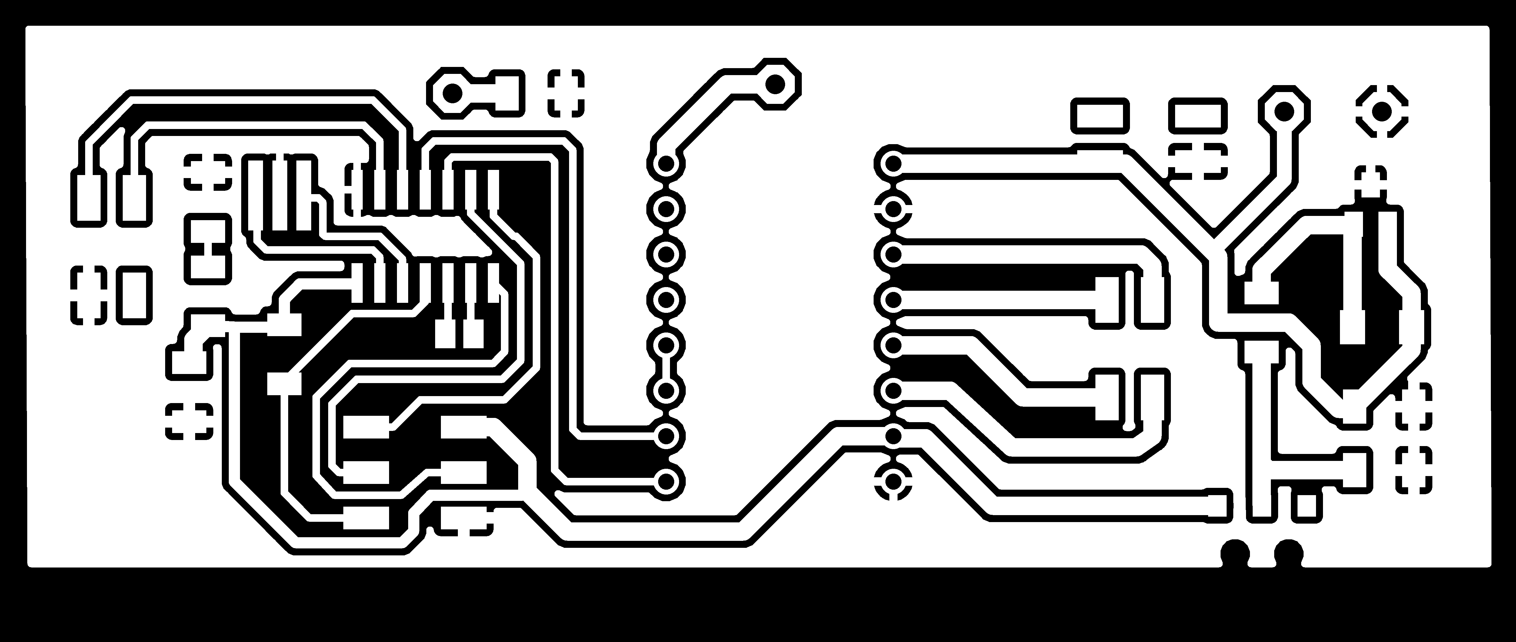
Stepper traces .png milling file
Stepper outline .png milling file
Arduino code for stepper 1 (lateral motor)
Arduino code for stepper 2 (vertical motor)
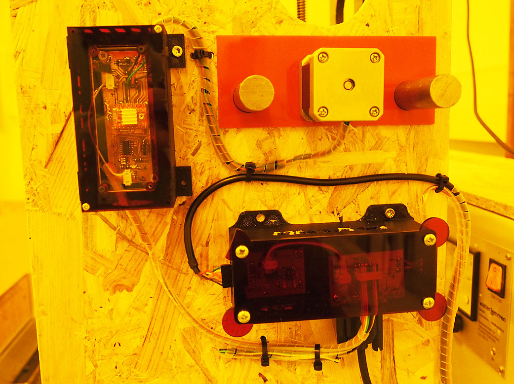
Power and network
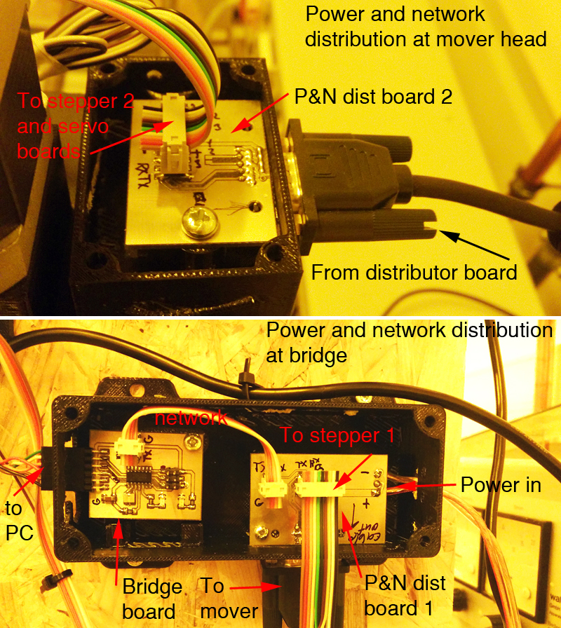
To distribute power and network for all electronics on my final project I had to design couple of extra boards. For communicating through serial network between computer terminal or GUI I used bridge board manufactured on week 15. There were no changed made on that bridge board, detail of it can be seen on week 15 page.
For the power and network distribution I designed and manufactured two boards. Their mission is to share the network and power around. Especially to the mover unit that houses one servo and one stepper motor controller board.
Here is the setup, Bridge board and distributor board 1 are in same box. Second power board is at the mover.
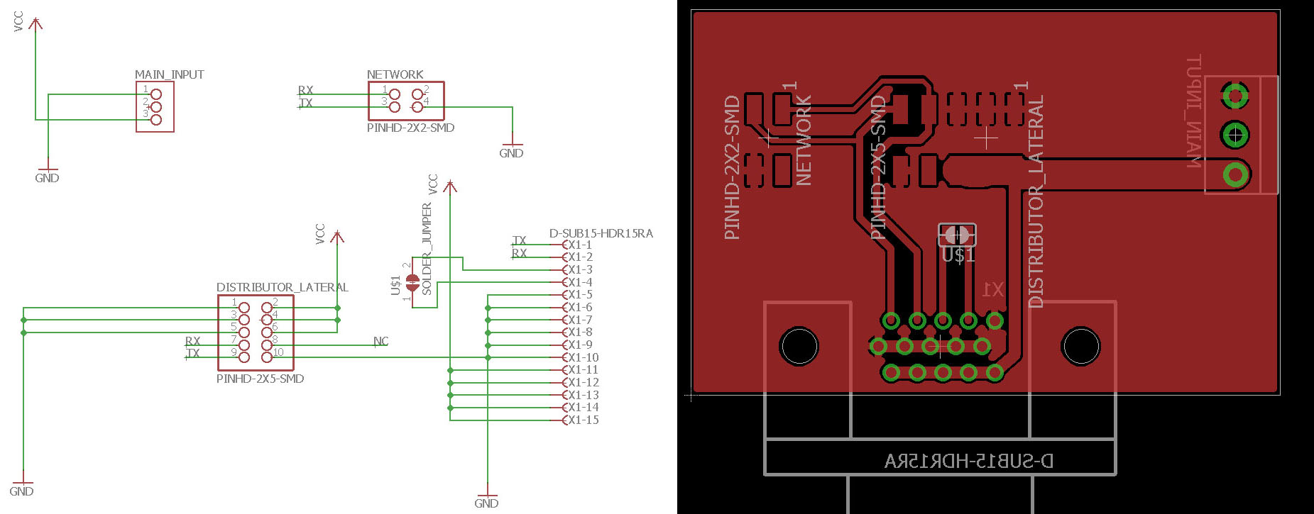
Here is the power and network board 1 eagle schematic and board.
Even though the bridge board is as it was on the networking week, there is a new code in it. It was coded and uploaded using Arduino environment.
Bridge board arduino code .inoboxes for electronics
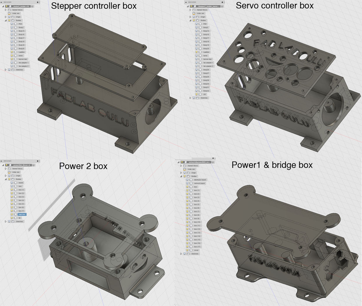
I made boxes for all the electronics. There are two stepper motor boxes that are identical. One servo controller board box, one box that holds bridge and power distribution board and one to hold second power board. All of the boxes have covers on them. Boxes were 3D-printed and covers were laser cut.
Stepper controller board box .stl file
Stepper controller board box .f3d file
Stepper controller board box cover 1 .stl file
Stepper controller board box cover 2 .stl file
Servo controller board box .stl file
Servo controller board box .f3d file
Servo controller board box cover .stl file
network1 board box .stl file
network1 board box .f3d file
network1 board box cover .stl file
network2 board box .stl file
network2 board box .f3d file
network2 board box cover .stl file
Adapter pieces for motor and trapetsoidal screws
I made adapter pieces to attach stepper motor and slide bars on their right places. On the other end there is a slot for ball bearing. Pieces can be seen on the picture in blue.
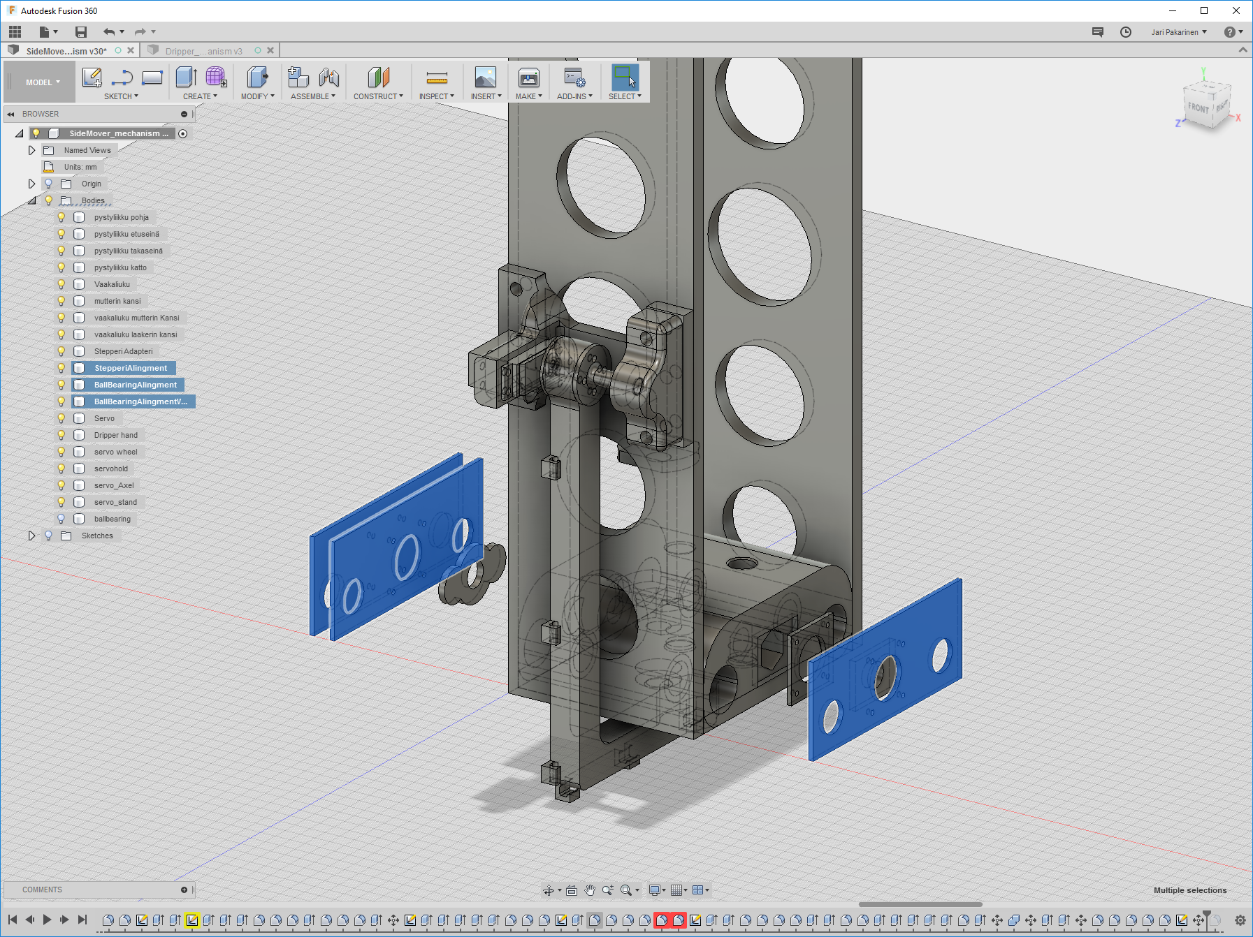
Parts were made by lasercutting from acryle. Laser cutting is explained on week 3. These parts can be seen on multitude of pictures on this page so I will not attach any here. Here are the files.
Motor adapter piece .stl filebearing aligment piece .stl file
Motor aligment2 piece .stl file
Programming
On the final project I used Arduino environment for program my electronics. I had installed Arduino environment earlier on week 10 - Output devices. To make it work with ATtiny44A microprosessor I had to install some extra material. I followed a good documentation from Ivan Sanchez Milara's week 8 page.
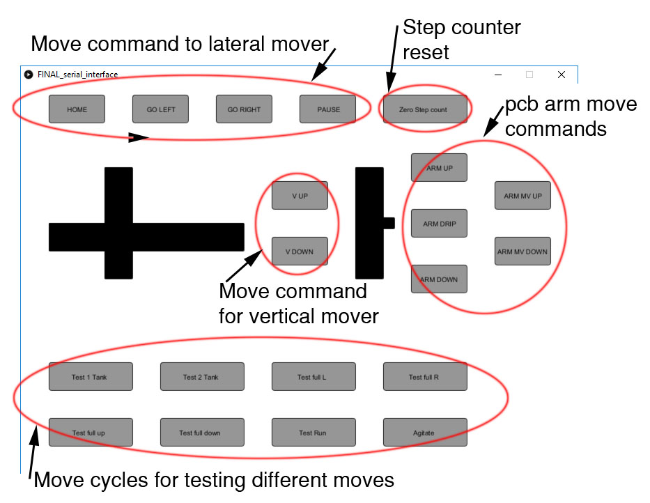
User Interface
When testing the system I used terminal to command the machine. This type of operation is explained on networking week week 15. For the final setup I desided to make a GUI using Prosessing software. User interface programming is explained on week in week 16. I made this GUI to test different aspects of the machine. There are many buttons for testing the system. GUI looks like this:
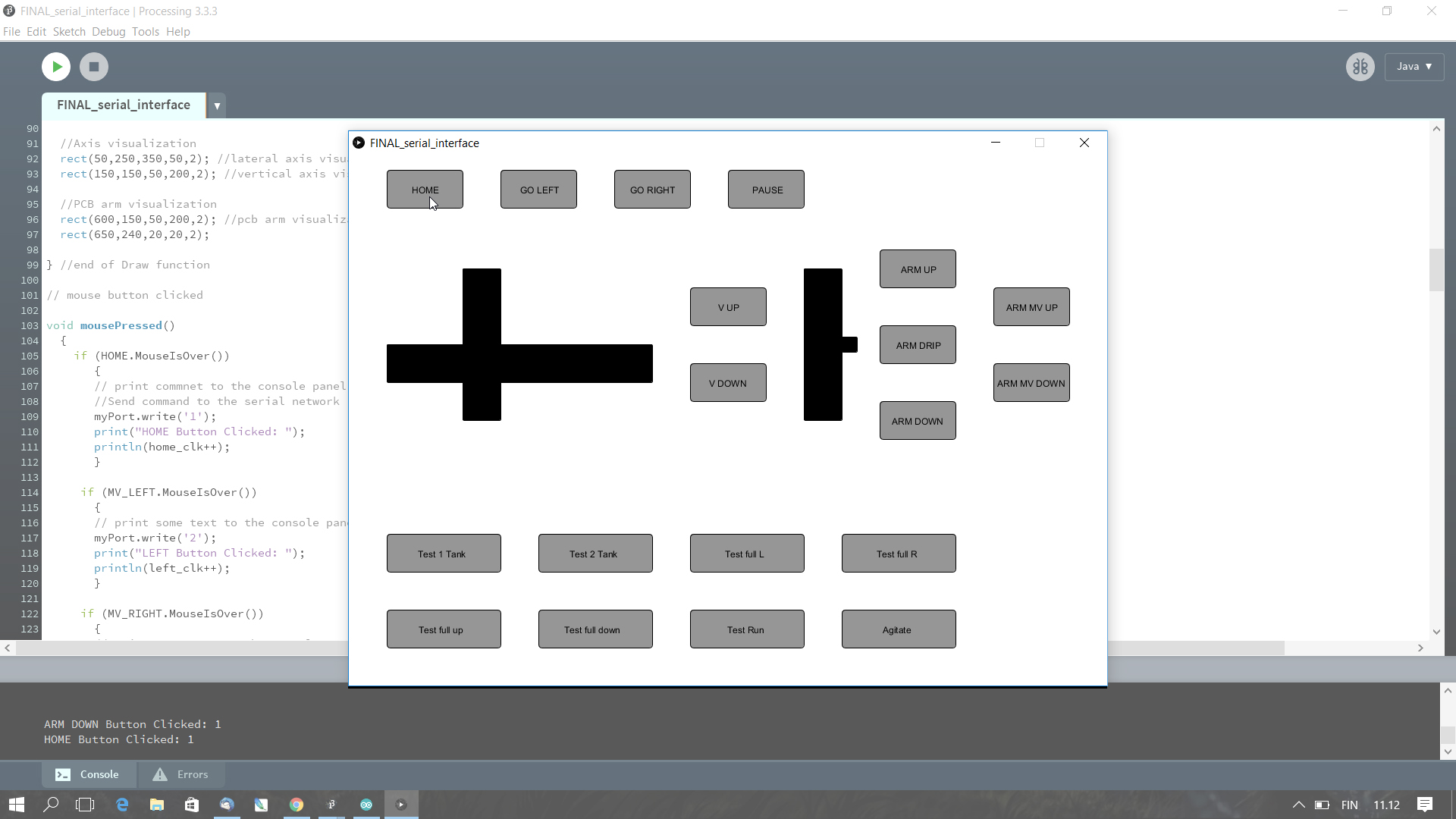
Interface prosessing software .pde file
To run the interface you need to have something attached to the serial port. I have COM3 in use usually. To see the interface in use see the final presentation video.
Hero Shots of the machine!
To see the final presentation video and slide, here are the links. Final presentation and Final presentation slide
What comes to rights of this project I release all design here under Creative Commons Attribution 4.0 International Public License™
BOM
BOM is calculated in Euro currency. Only part prices are included. Shipment etc. costs are not in calculations.
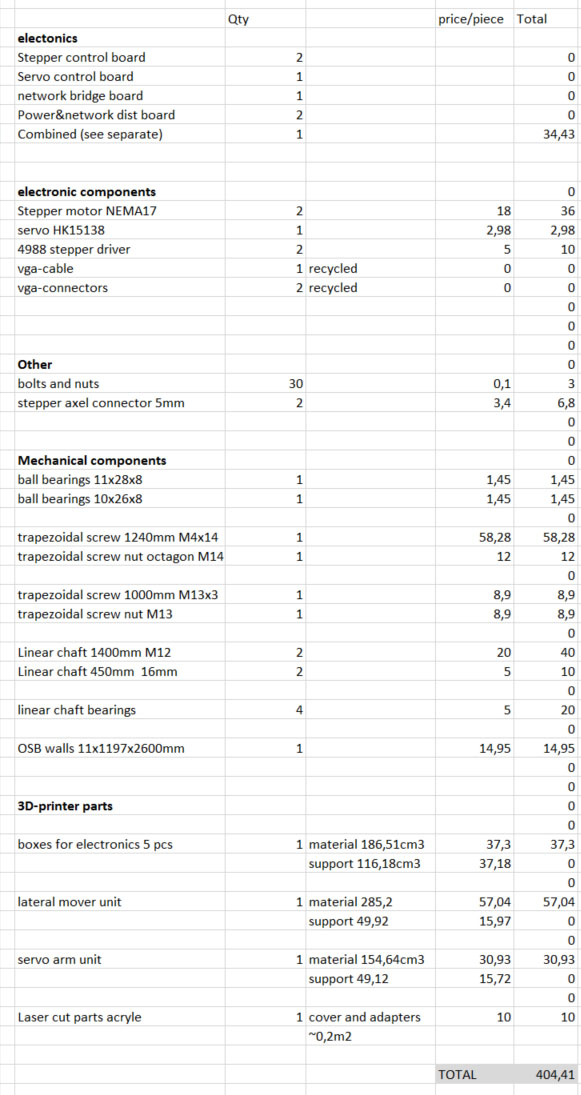
Electronics is included to the general BOM but here is more specific BOM for electronics.
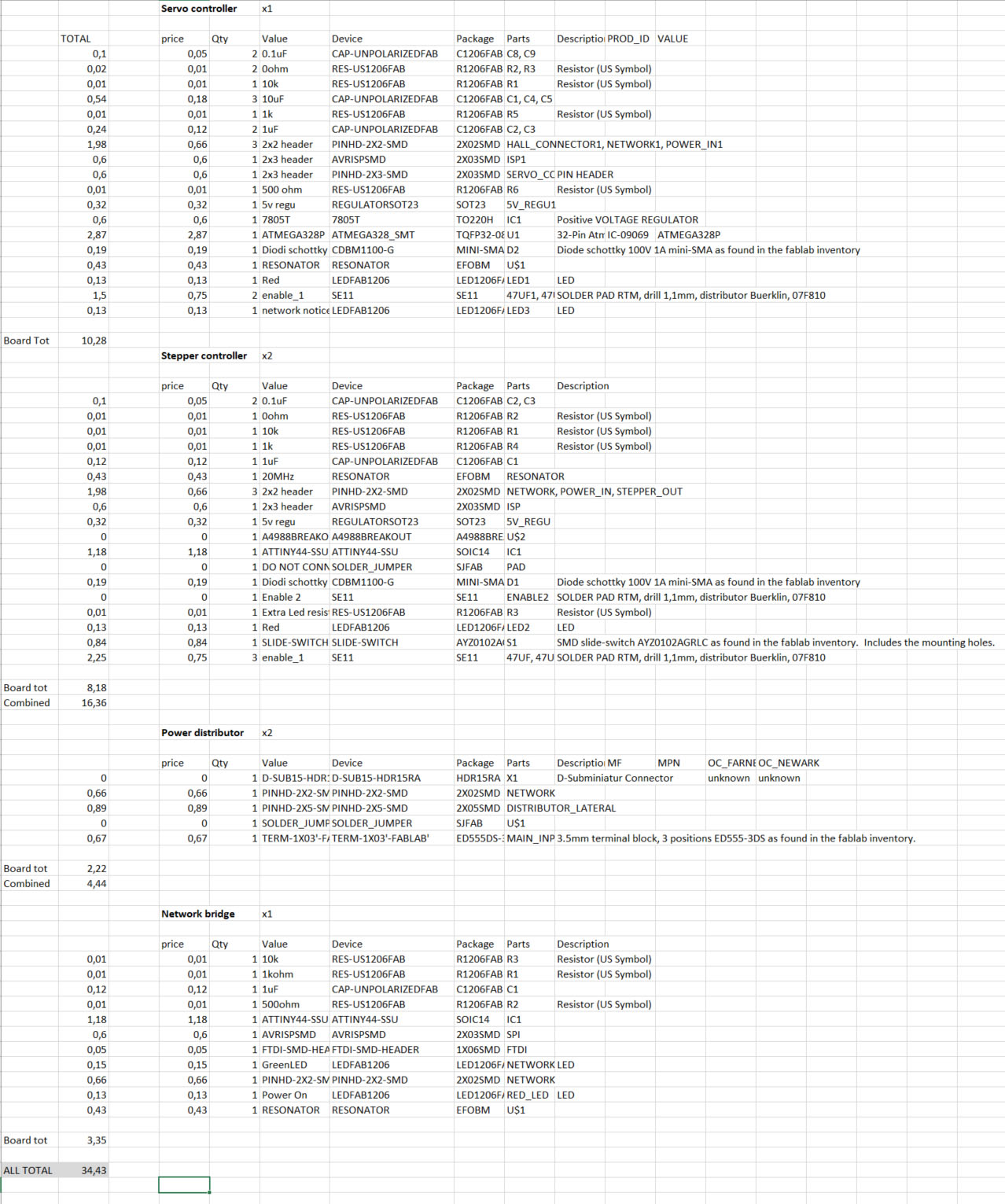
BOM calculation excel file.