Machine design
This page is a documentation of my personal contribution. This link is for our overall documentation.
About the machine
Our solar tracker uses sunlight to engrave a substrate with a low melting temperature for example wax. Sun light is sensed by four LDRs then stepper motors are used to control the build plate positioning it towards maximum light intensity. A fresnel lens is used to collect the incoming solar rays which are then focused into one point by another lens and eventually reflected perpendicularly towards the machine bed by a mirror. The bed moves along two axes, enabling the 2D solar engraving of the substrate.

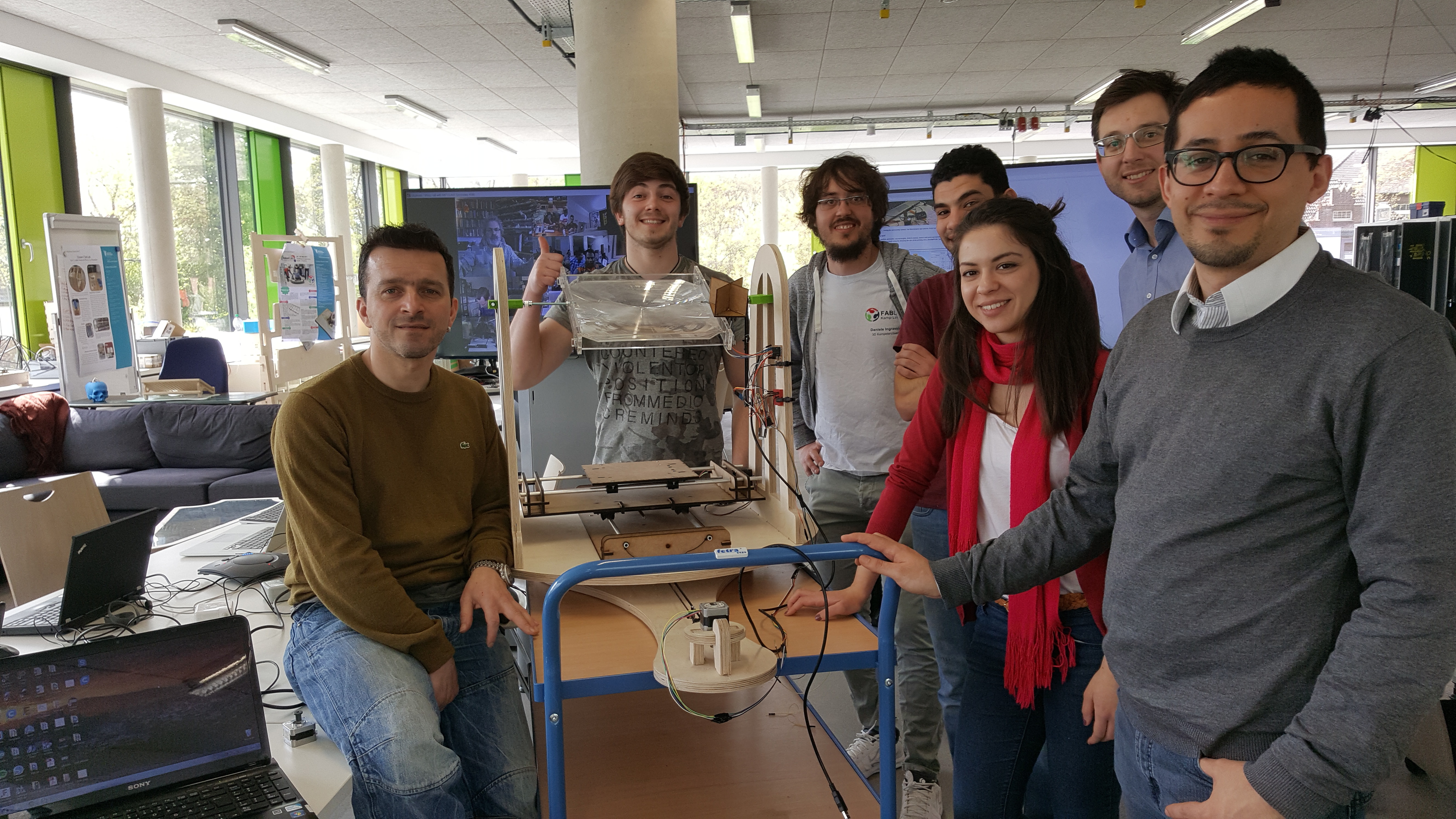
The team
- Ketlli
- Konstantin
- Dima
- Cesar
- Joern
And Me !! We were lucky enough to have Daniele as our instructor.
My contribution:
-Structure of the machine
-Mechanical movement
-Electronics
Structure of the machine
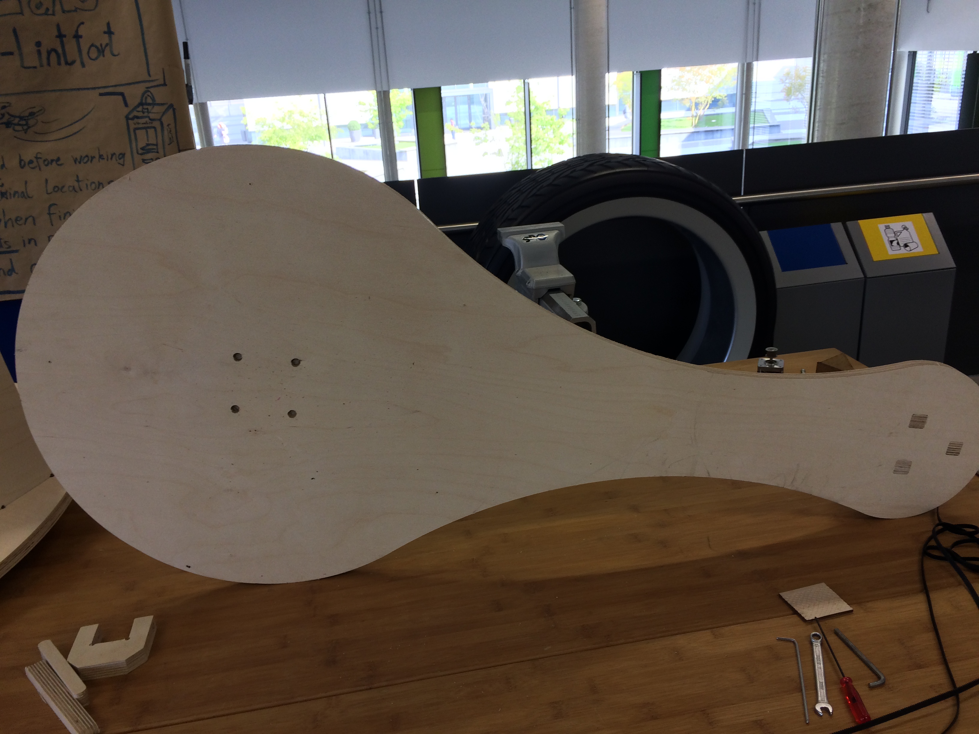
We decided to have a moving platform on which we should mount all parts of the machine. This platform should move according to the sun's movement. The reason why we decided to do this is becuase of the need of having a fixed home position for the machine relative to the focus point of the machine and also we need to keep the drawing point also fixed in the same way.
-I started drawing a 2D sketch of how this platform should be using Fusion 360.
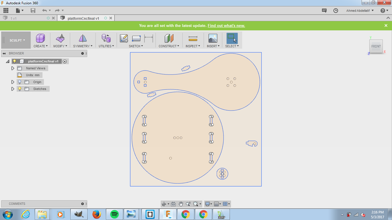
-I used the same commands mentioned before in previous documentation. The dimensions are based on the area required by the bed of the machine which is based on the dimensions of the MTM kits.
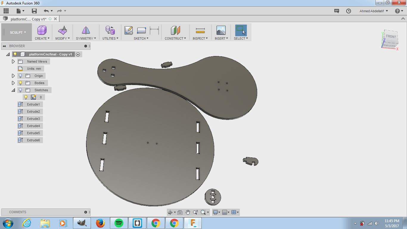
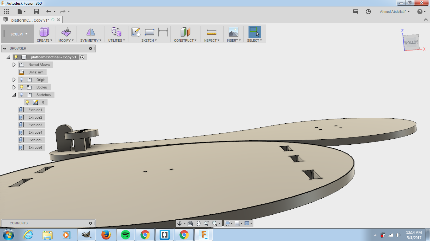
-I extruded the parts and assembled them together to make sure that they were gonna fit.
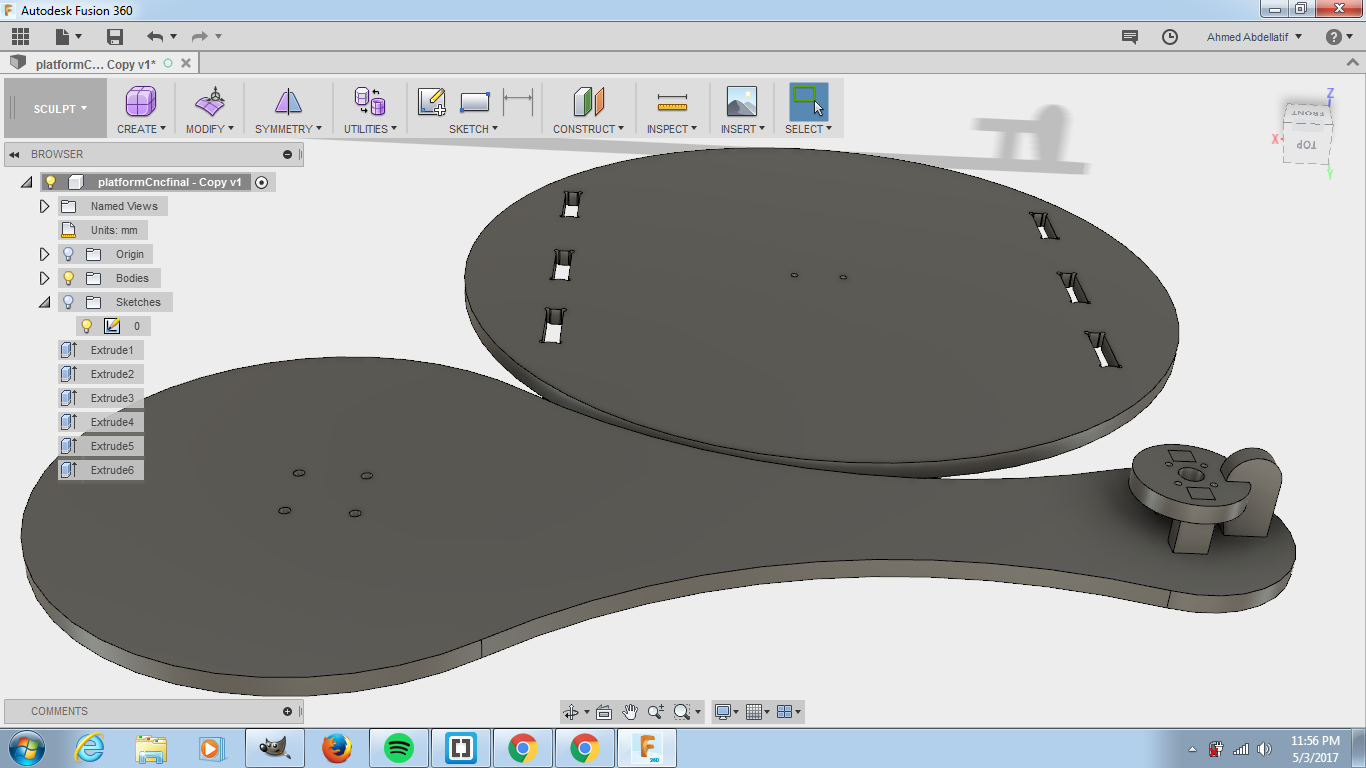
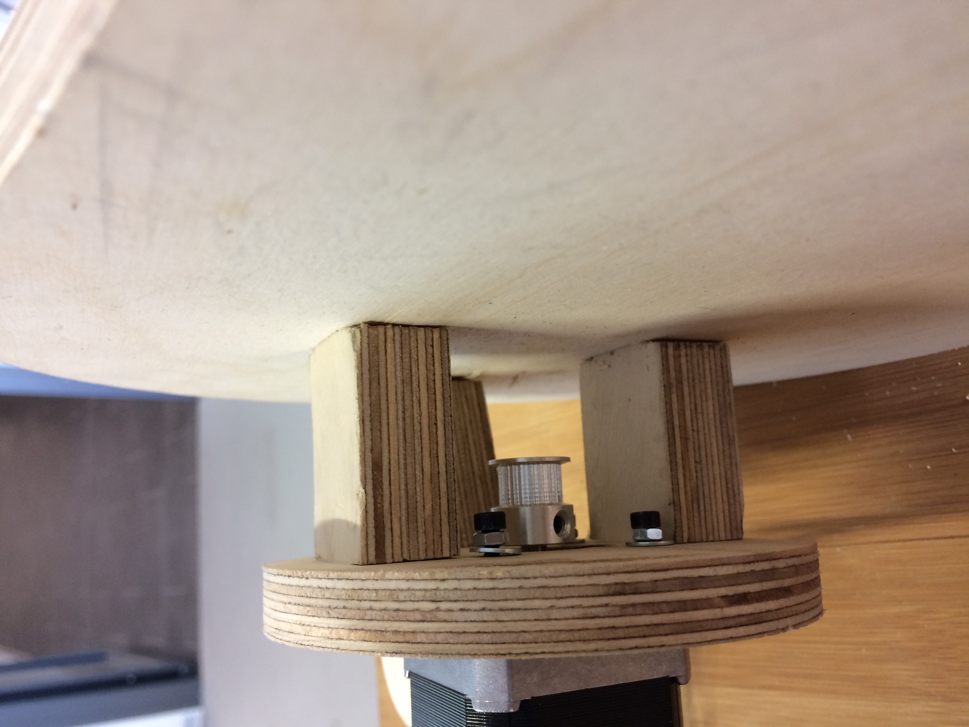
-The idea is that the small part should hold the stepper motor, the middle sized one is gonna be static to hold everything and the big one is the moving platform. For this mechanism to work we needed an extra part to link the static and the moving part together this is also documented below.
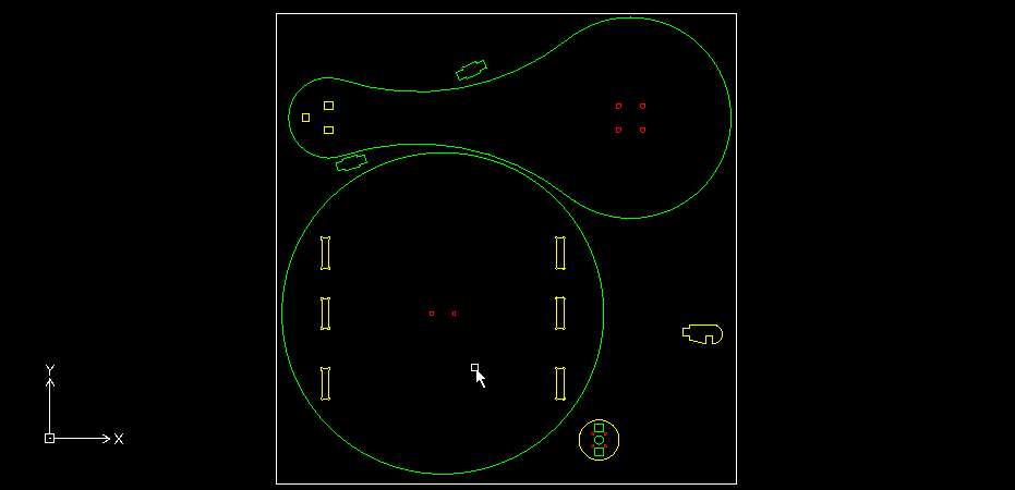
-I used EasyWorker MasterPro 2513 CNC machine to cut the parts out of 18 mm multiplex wood. Here are the settings I used:
Safe-Z-->70.00
Start-Z-->18.5
Final-Z-->-0.02
Z INcrement-->2.6
FeedRate-->2000
PlungeRate-->800
SpindleSpeed-->18000
Spindle direction-->CW
Method-->I chose Inside CW for the slits of the joints only and for the other jobs I chose Outside CW.
Mechanical Movement
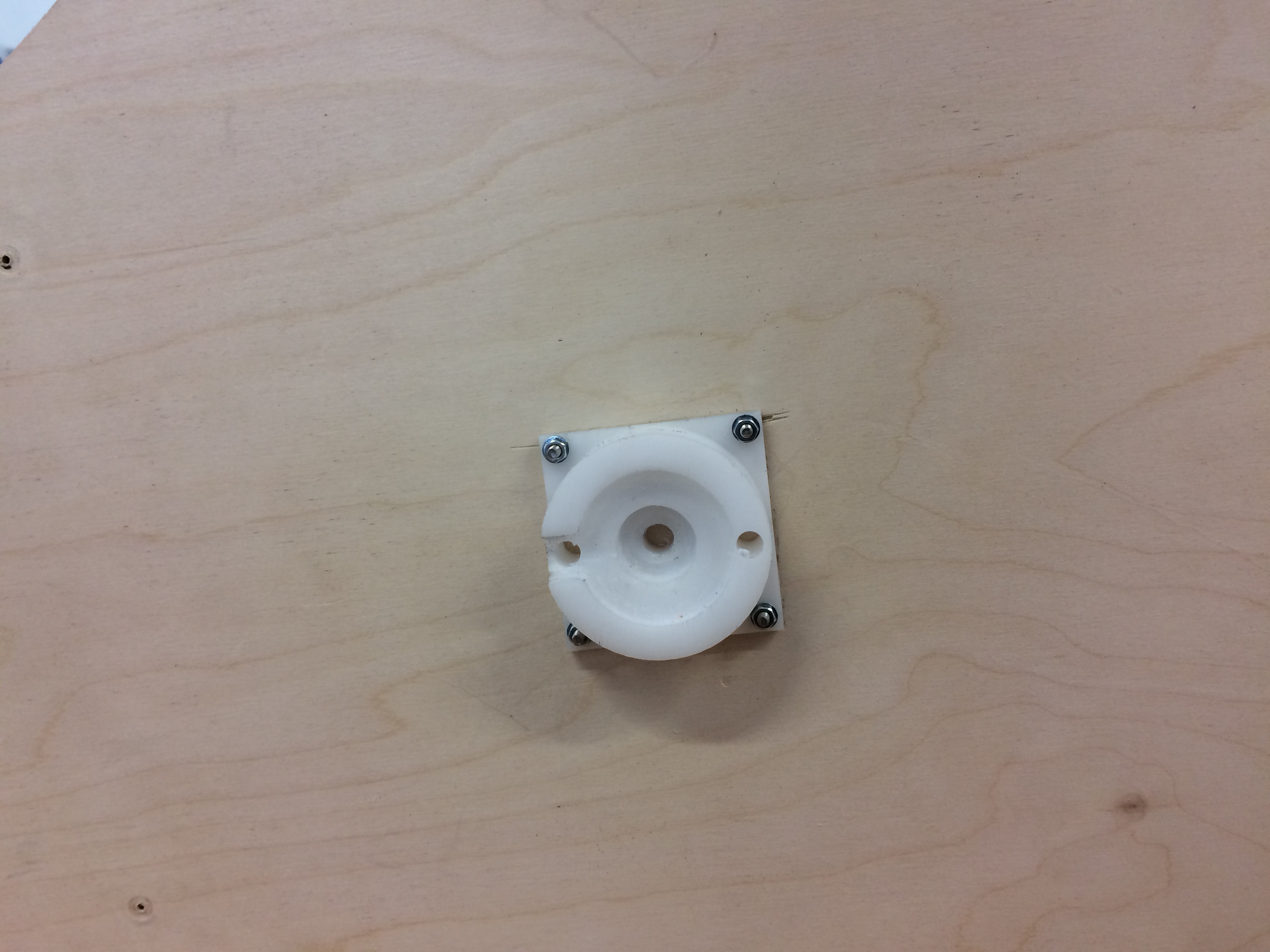
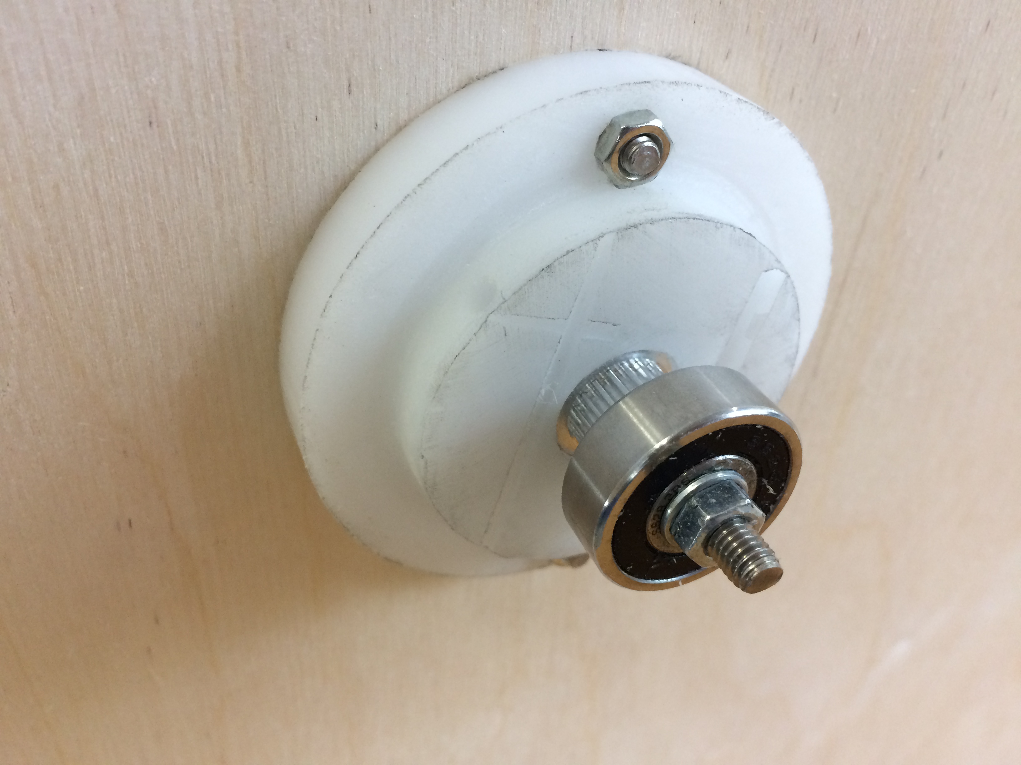
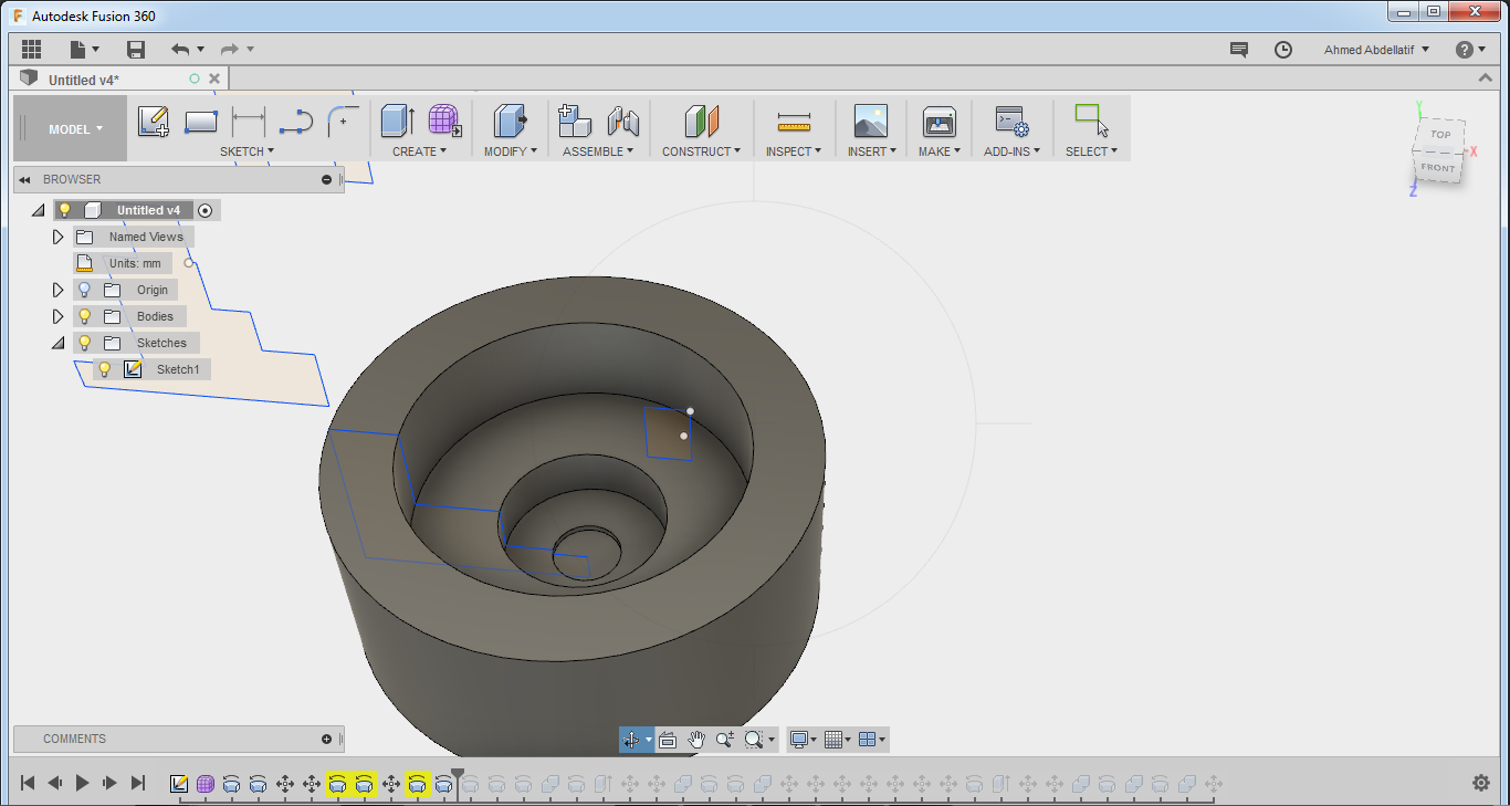
As we needed a way to attach the bed of the machine to the platform while maintaining the rotatory movement between them I came up with the Idea of having a base or a collar to hold a ball bearing with should be attached to the other moving part .
-I started by drawing a 2D sketch of this Piece using Fusion 360.

-I revolved the sketch into a 3d object.
-I added a new setup. This is documented in details in previous assignments

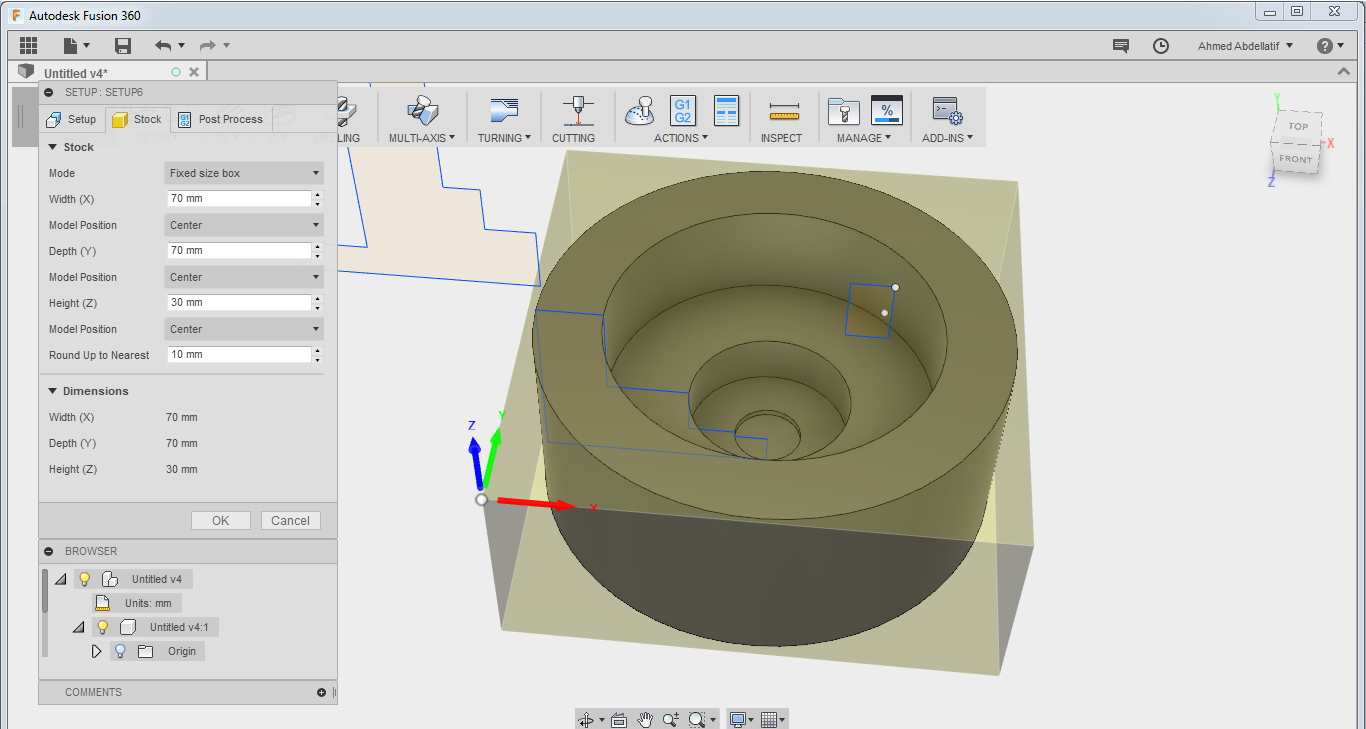
-I added an adaptive clearing milling strategy.
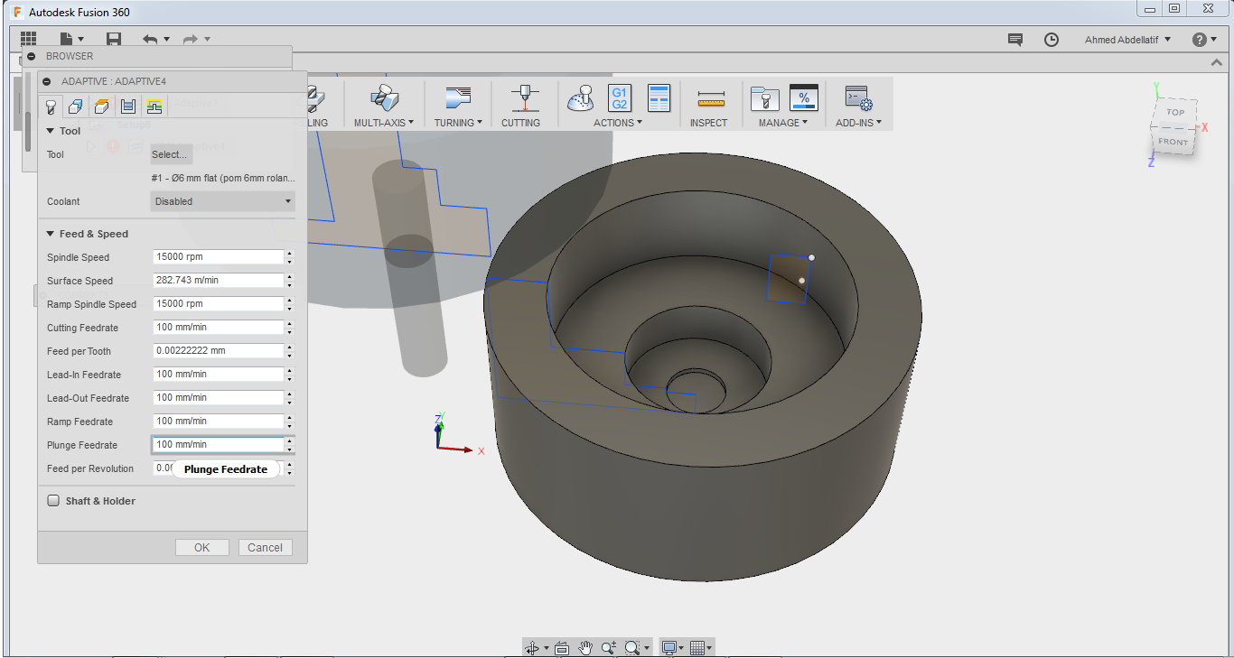

-I simulated the process to make sure that I have no collisions.

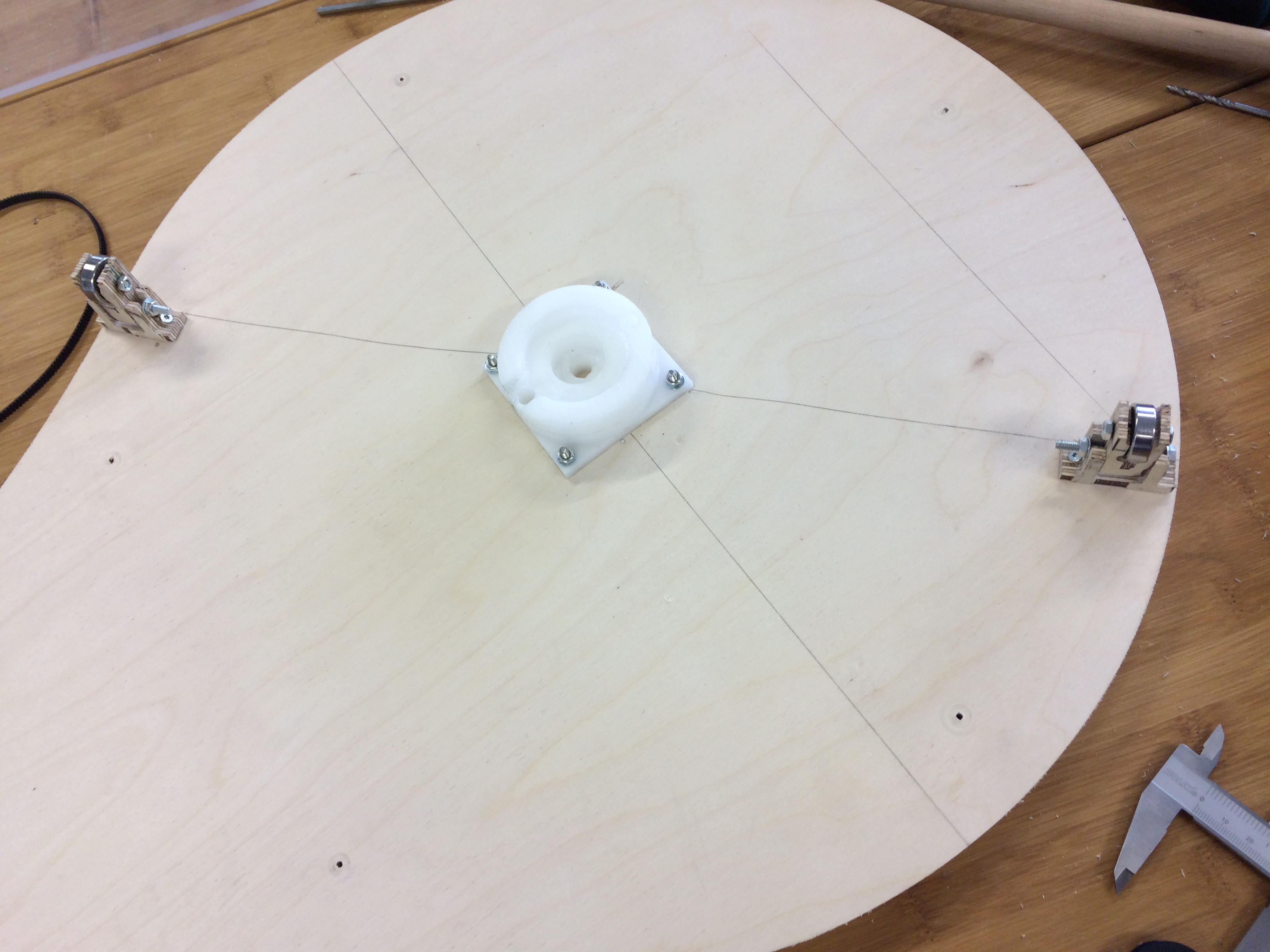
Electronics
I used my assignment for output devices to make the electronics for this machine. Eventually we used different electronics but we used the ones that I made to test the mechanical movement
-This is documented in the page of Output devices .

Final product