
FabPCBMaker
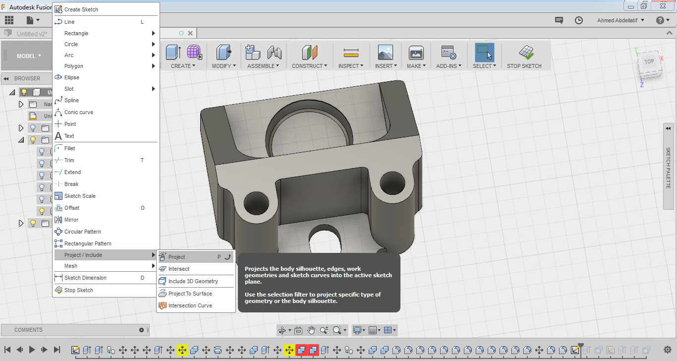
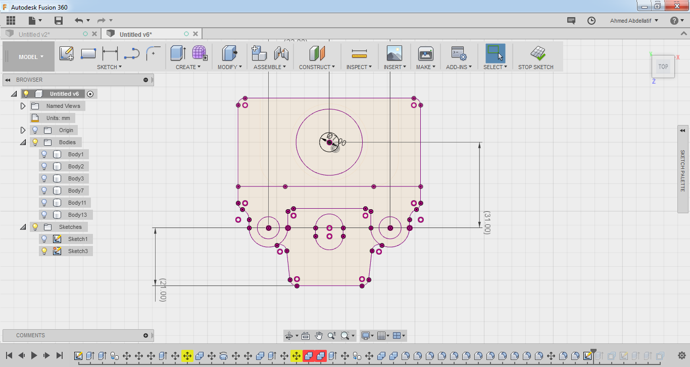
First step after creating my rough sketch was to draw a 2D sketch of the parts of the machine.
Structure
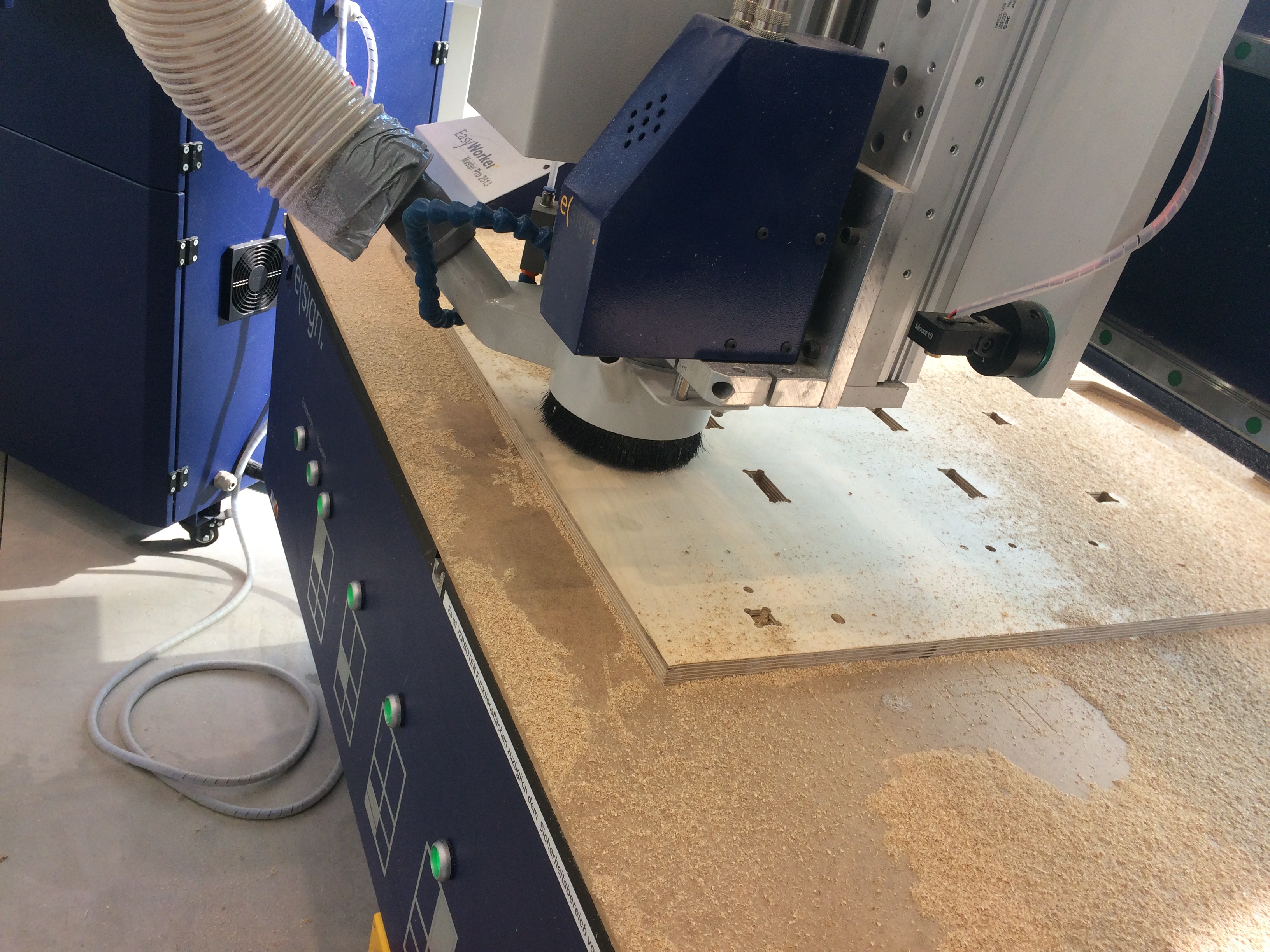
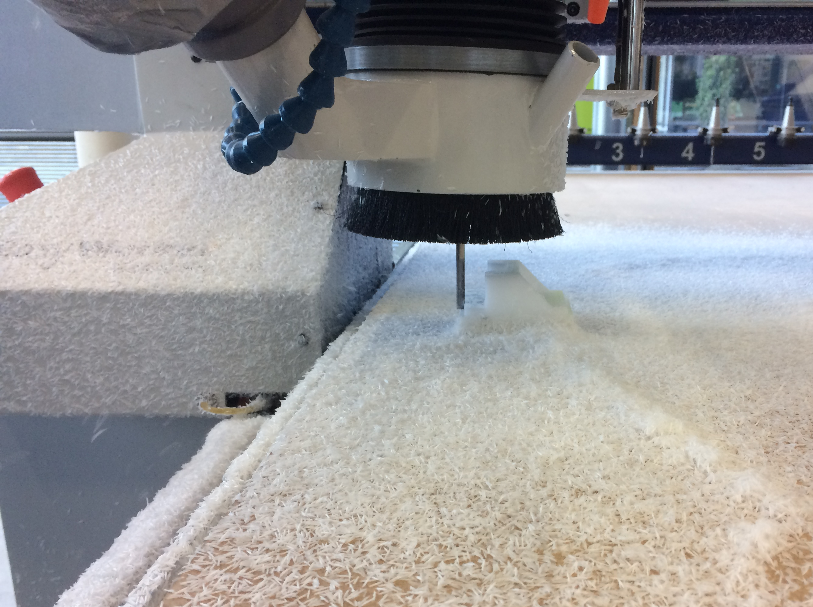
- I decided to use fusion360 as I became quite familiar with using it to design the structure. My idea is to use 18mm plywood and cut it using the CNC machine.
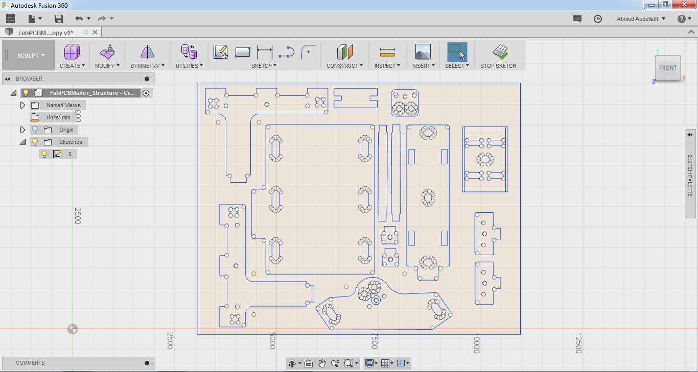
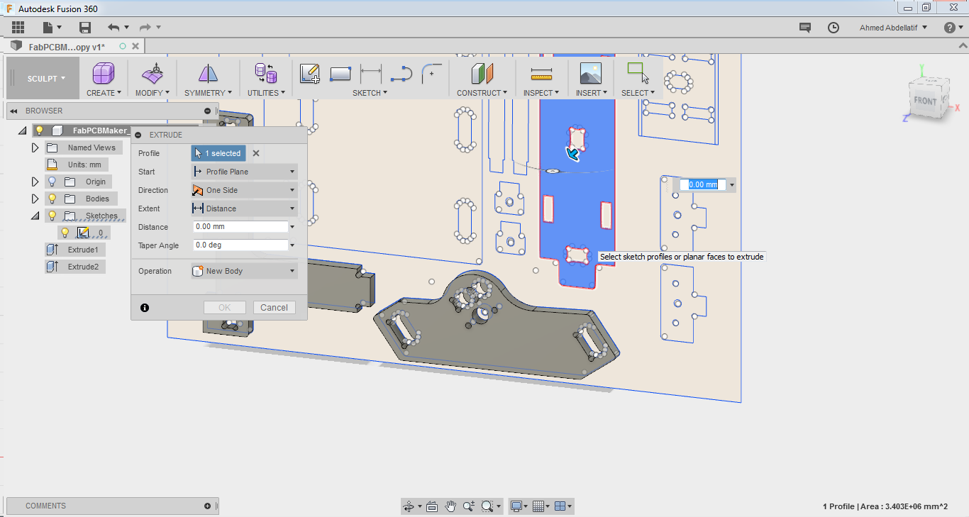
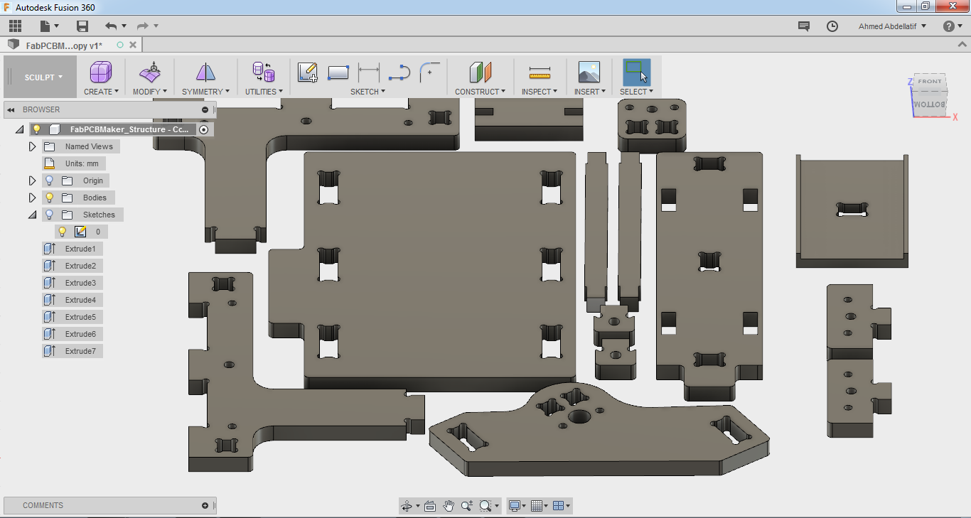
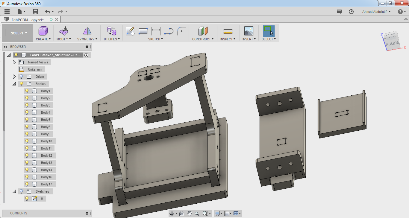
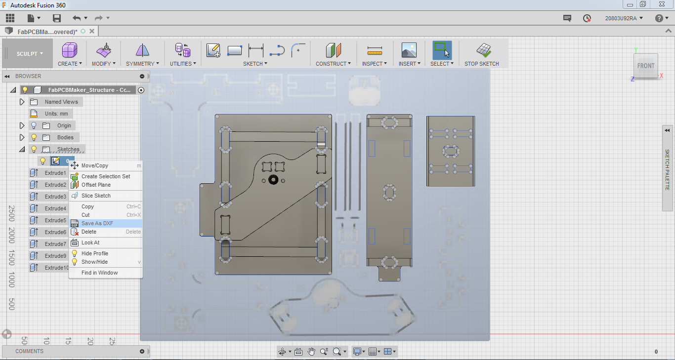
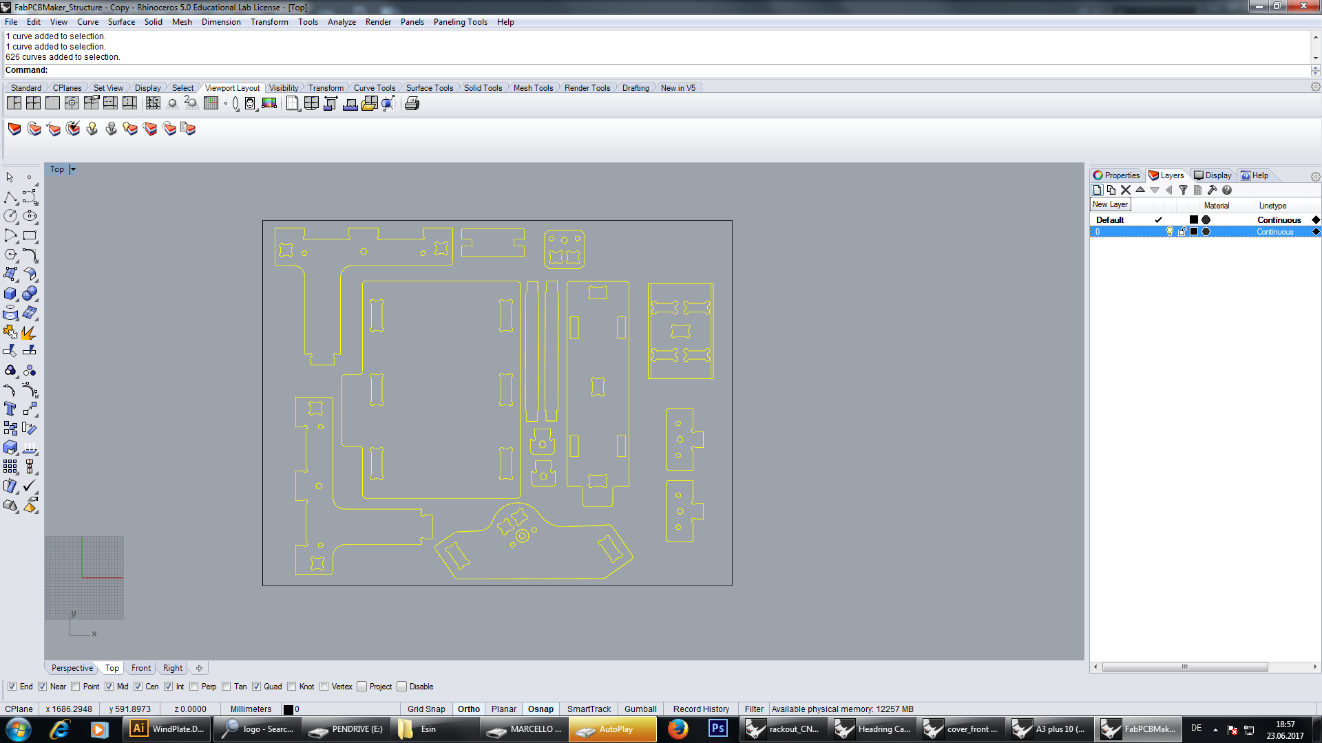

-Here are the settings I used:

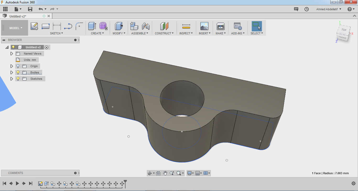
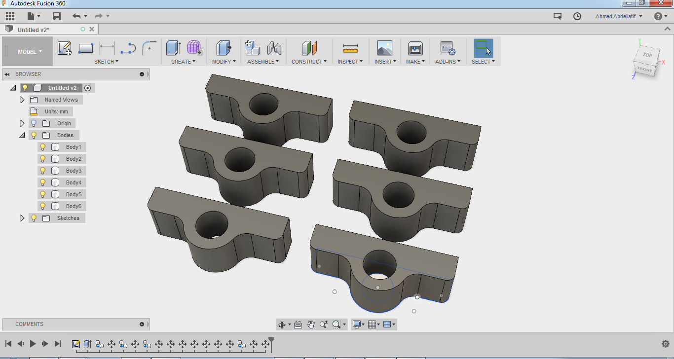
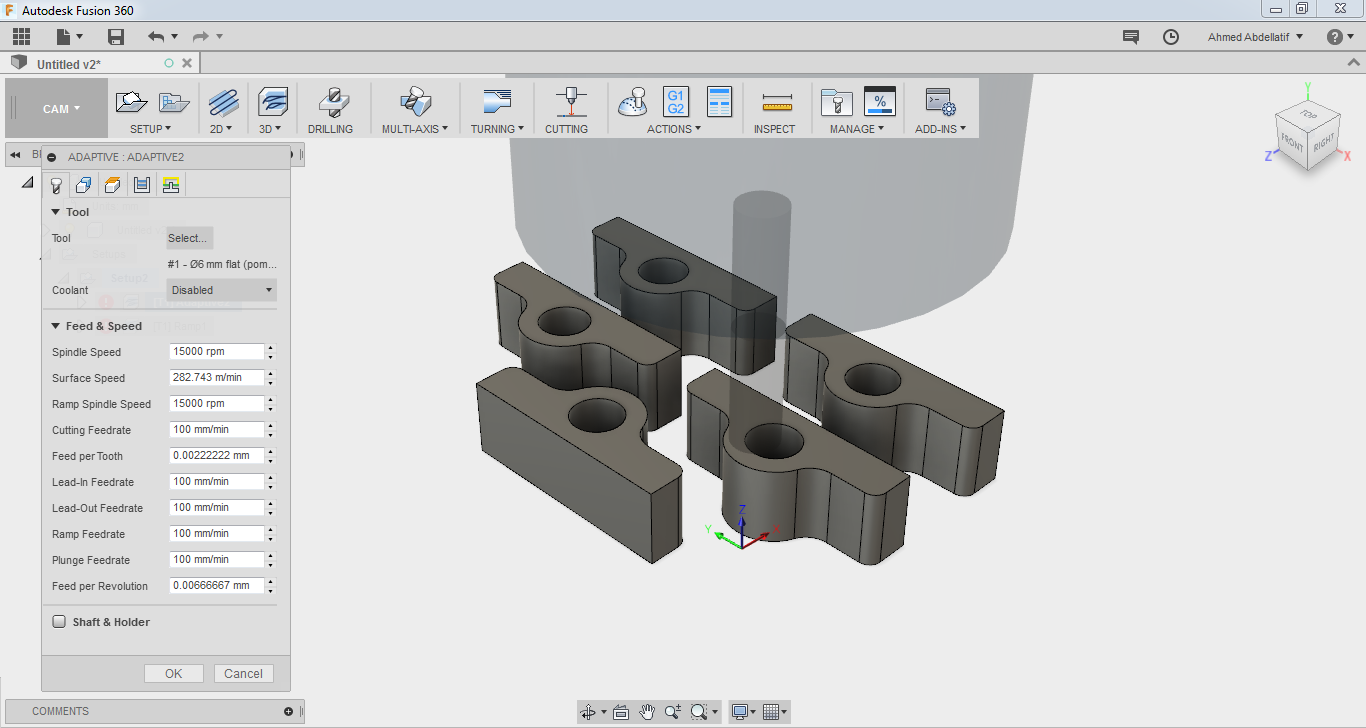
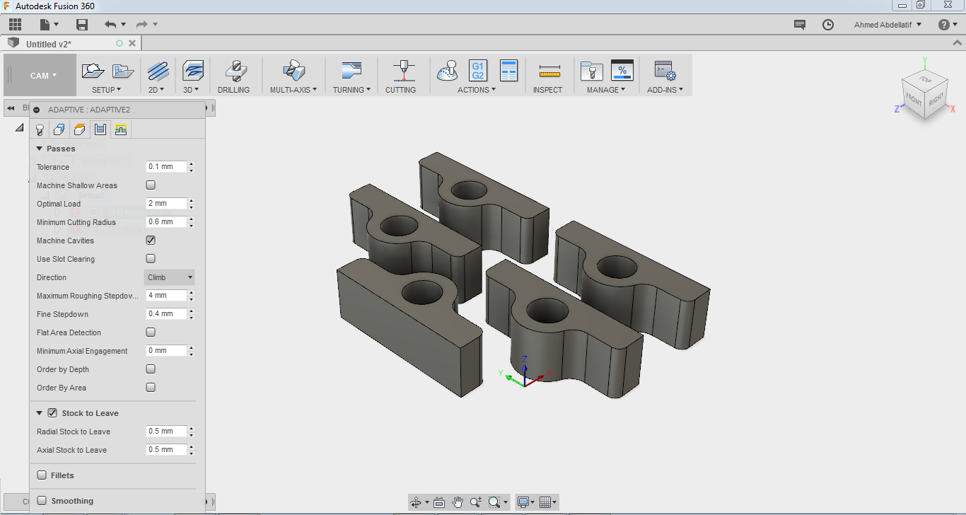
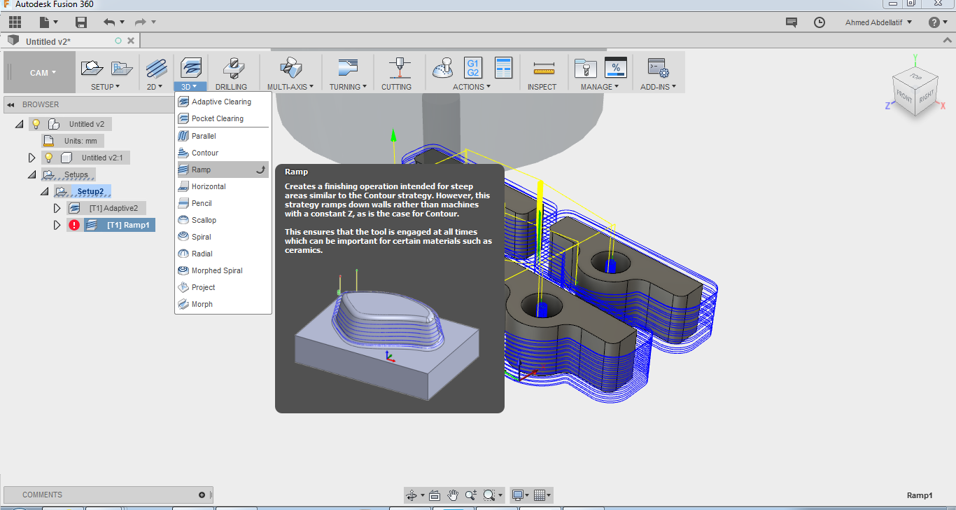
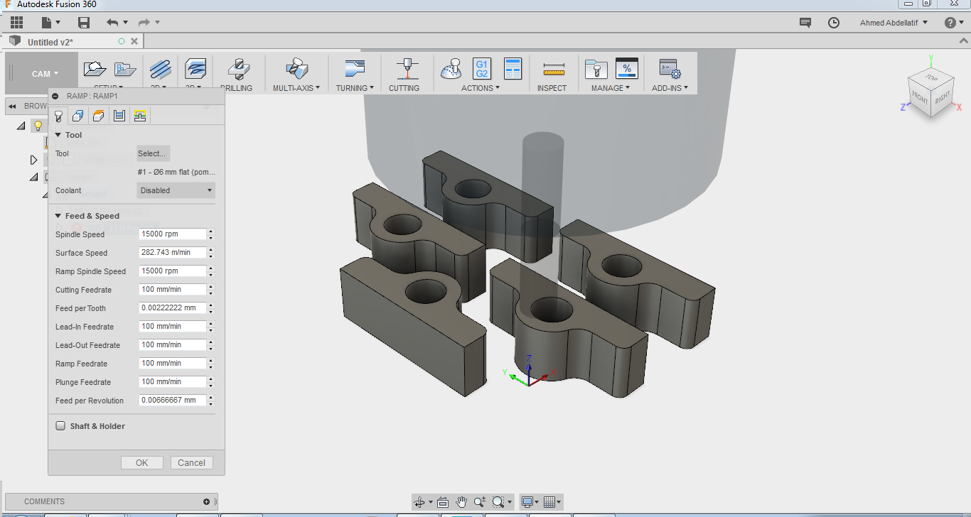
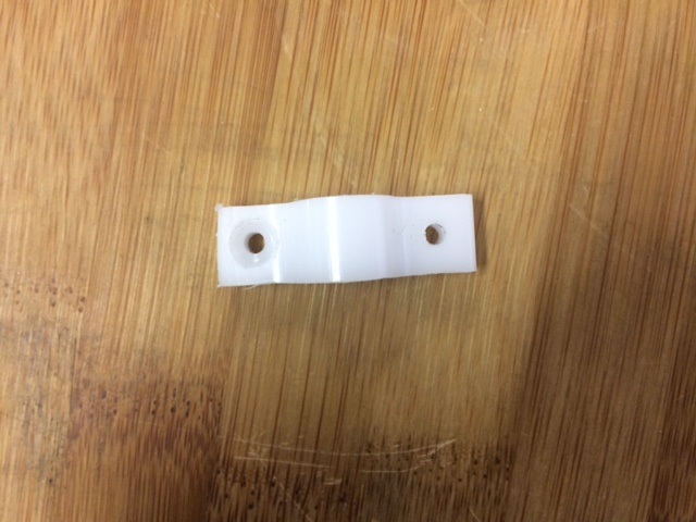
Bearings
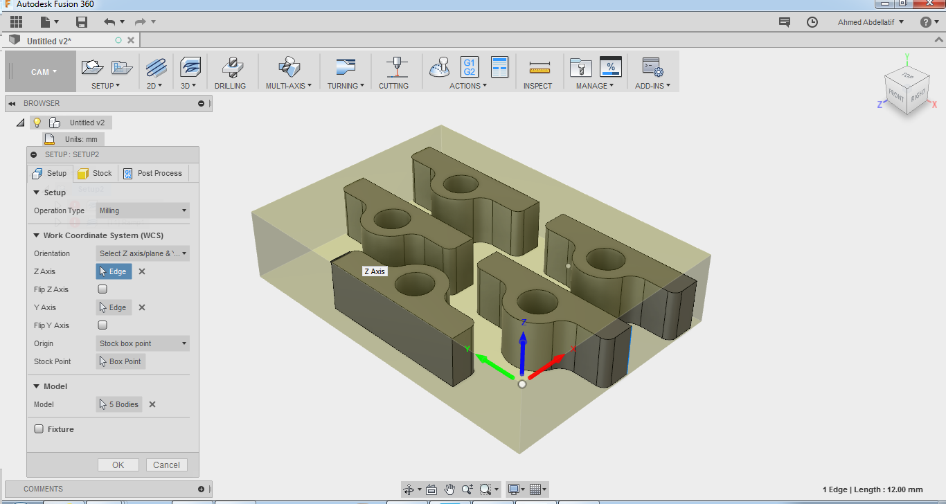
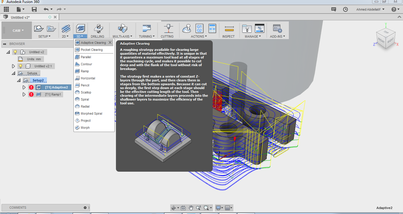
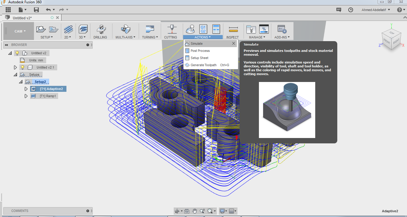
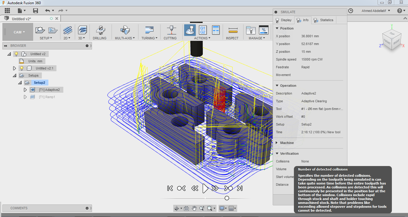
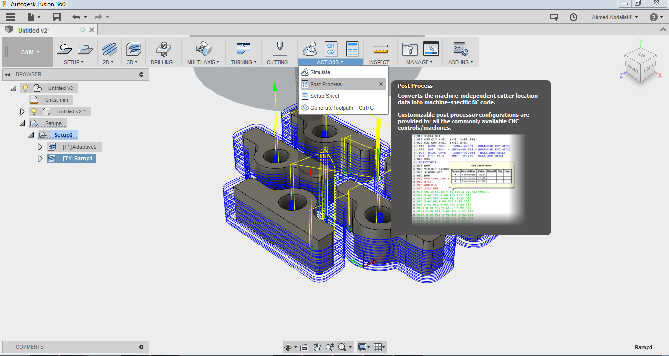
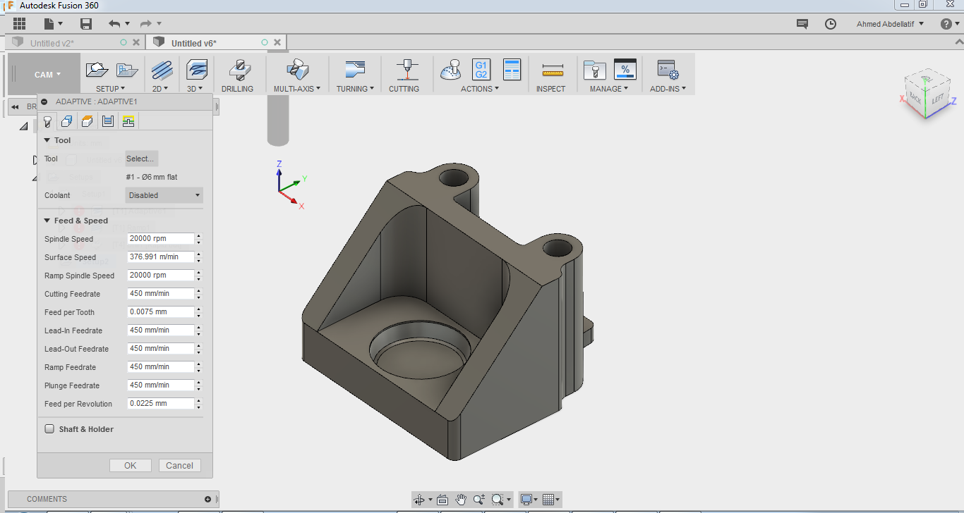
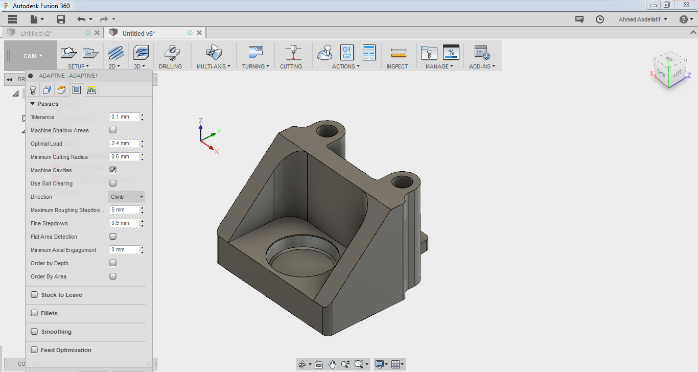
I decided to make my own bearings for the linear guides. My idea was to use POM and machine it using the CNC. Again I used Fusion360 to design the bearings and I also used the it's cam processor to generate the milling G-code.


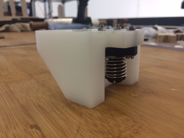
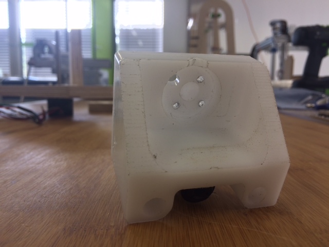
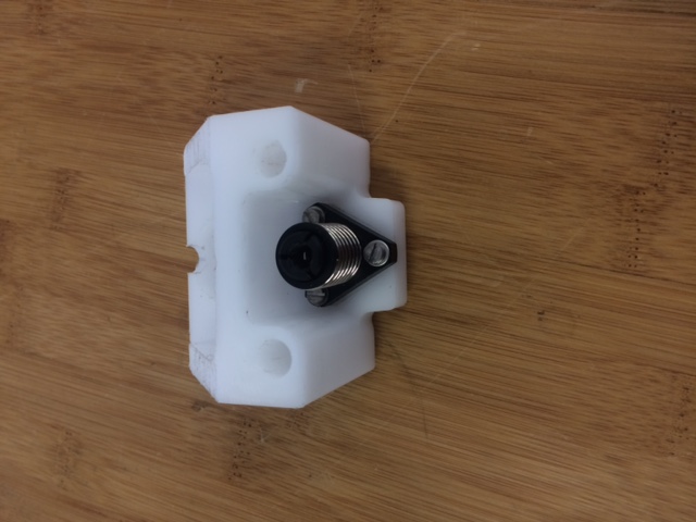
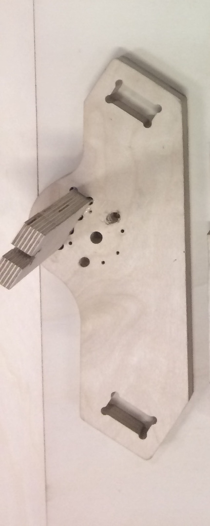
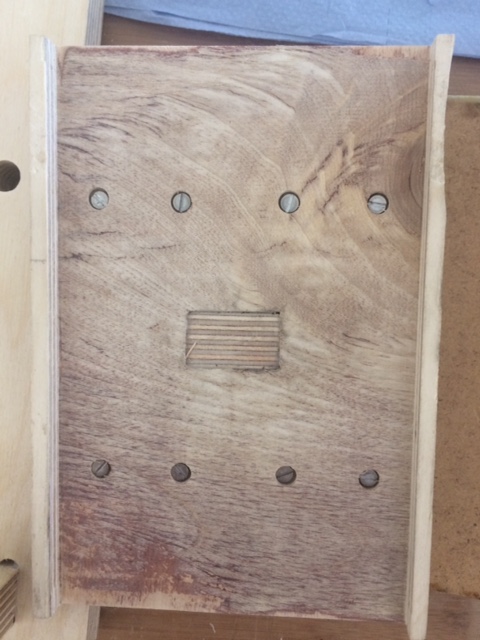
Motor holder
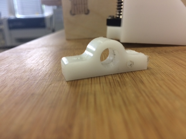
For the motor holder I decided to use the same material as the bearings, fusion360 to design it and The Easy worker CNC machine to mill it .


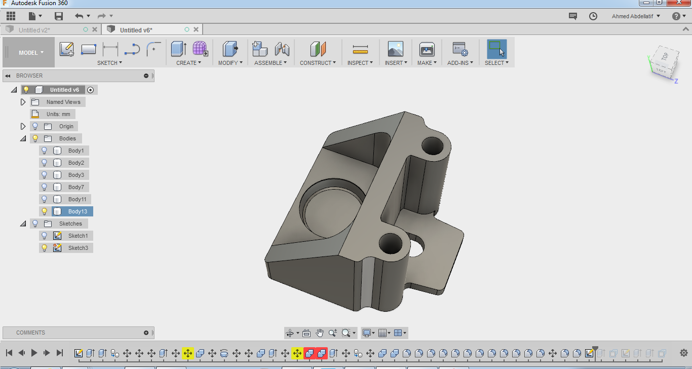


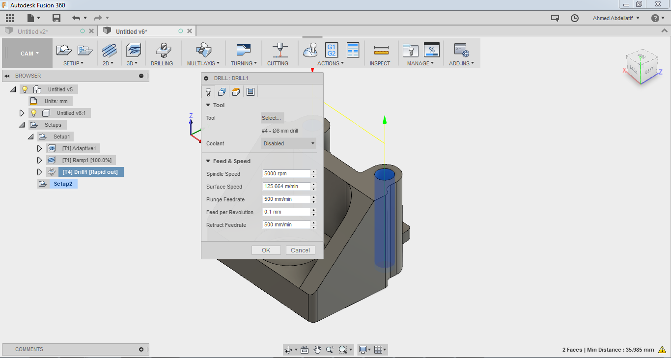
- I made some holes manually and attached the threaded collar of the stepper's screw

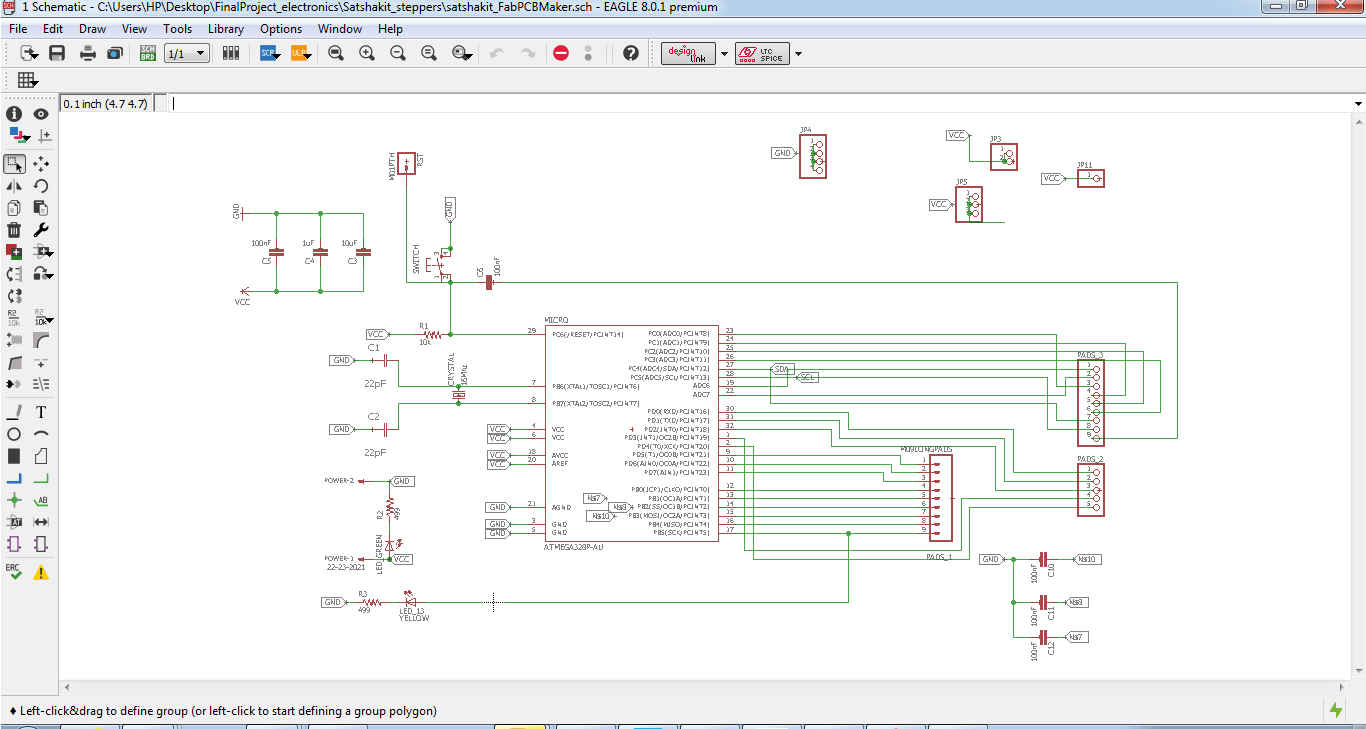
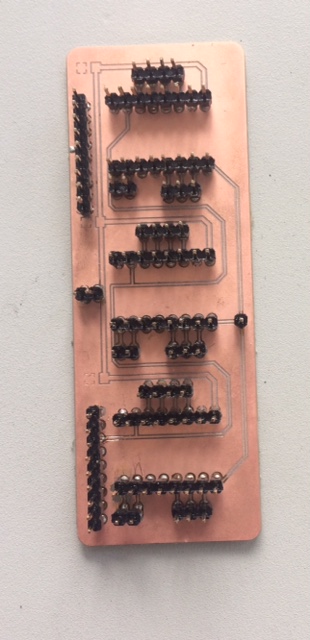
Electronics
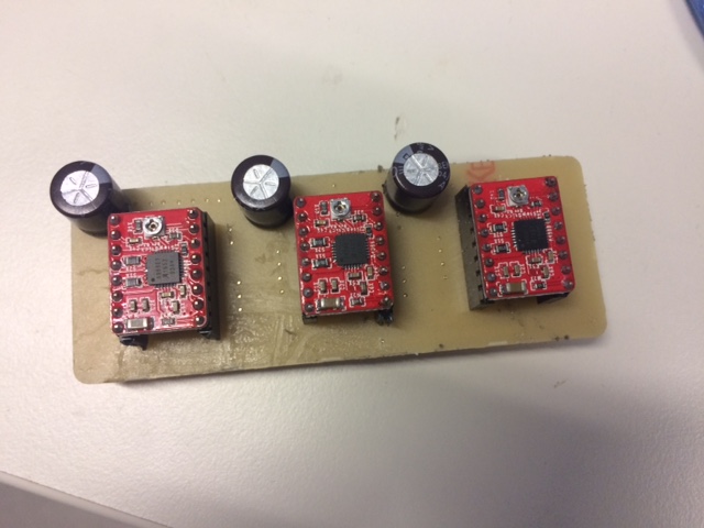
Regarding the electronics of my machine I decided to be as efficient as possible, meaning if it's cheaper to make it on my own I make it, If otherwise I buy it. Following this approach I decided to make a microcontroller board and a distribution board but buy the stepper drivers.
The microcontroller board is a slightly compact version of SatshaKit and the Stepper drivers are Pololu A4988 .
I used Eagle to design the PCBs and Roland MDX-40 machine to mill them.
Microcontroller Board
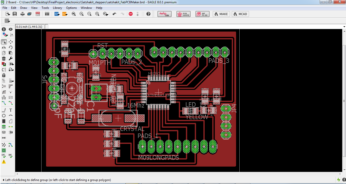
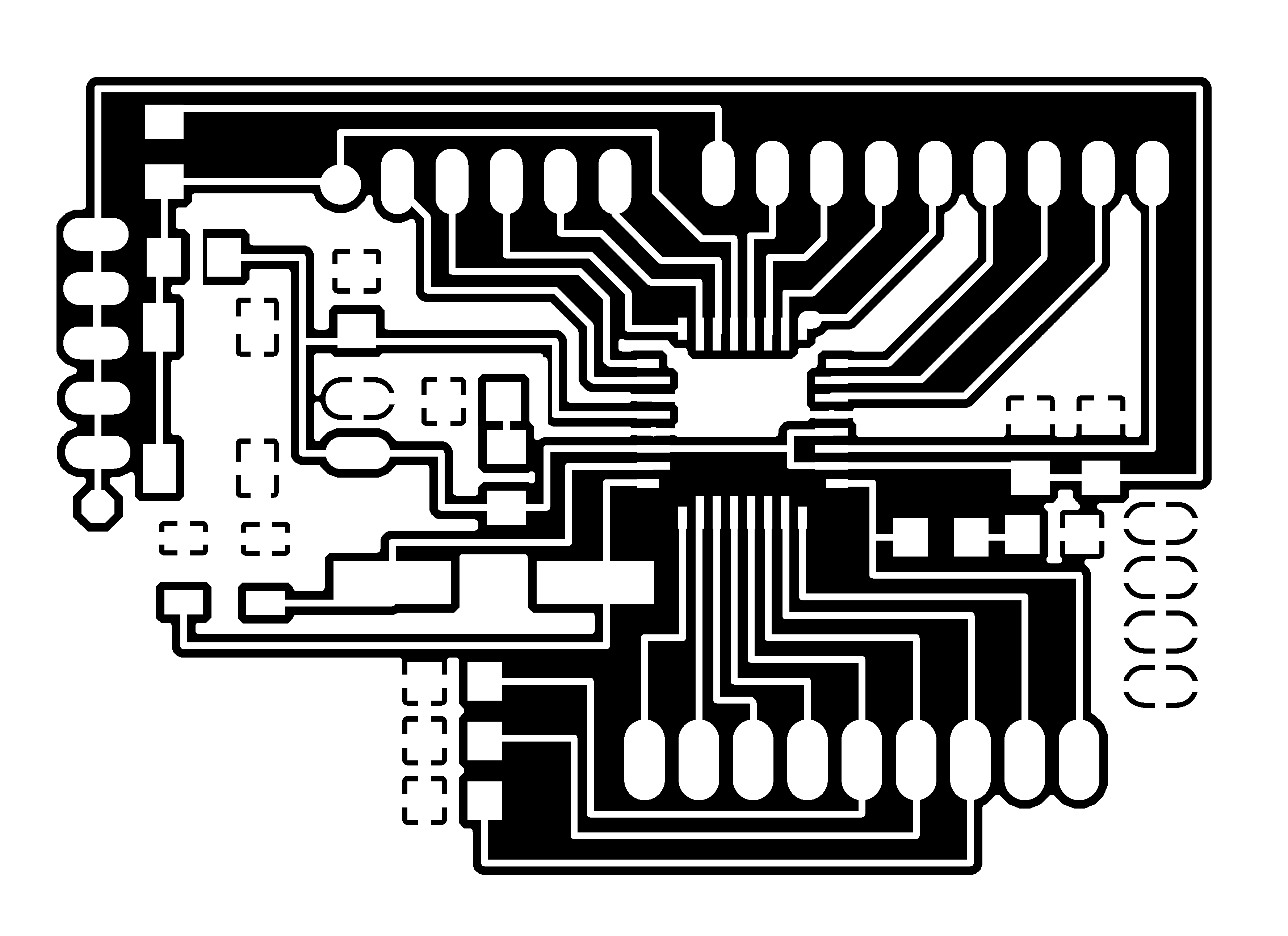

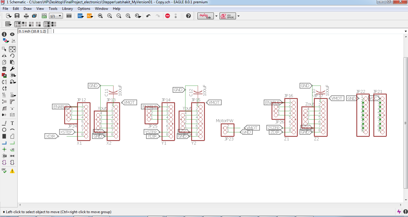
Distribution board

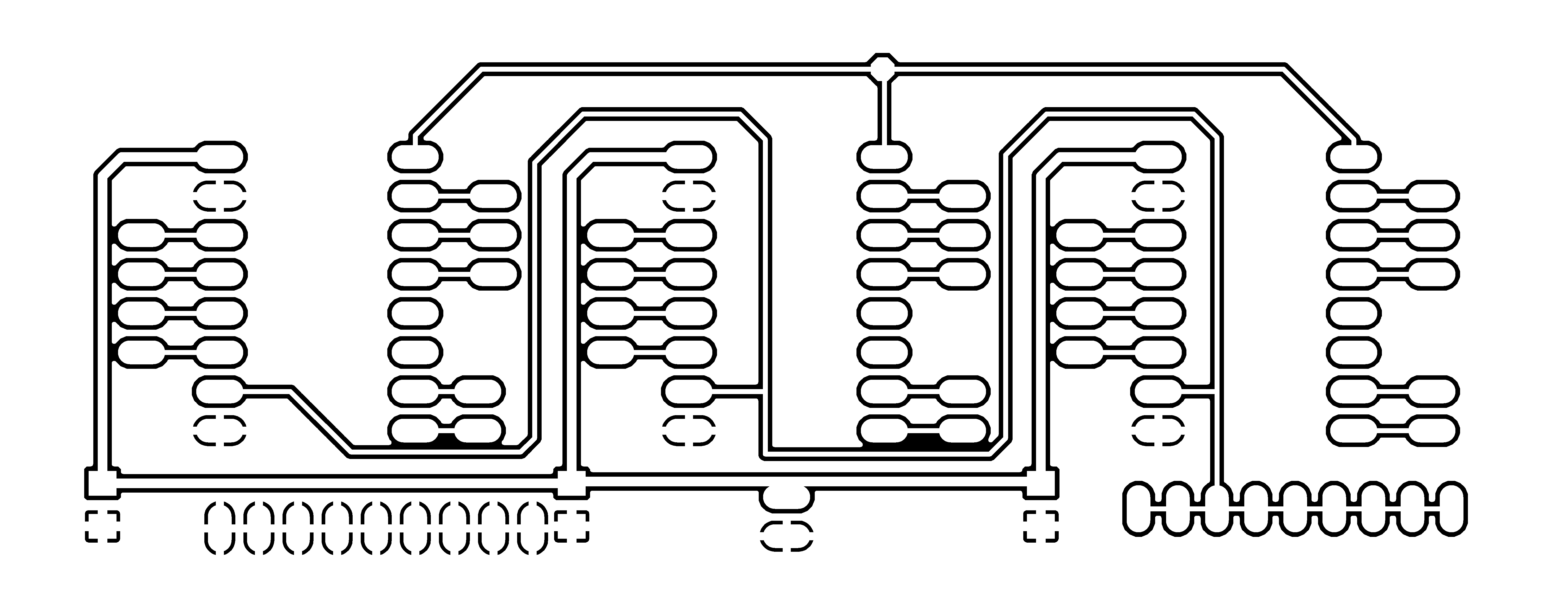

-Here are the settings I used:


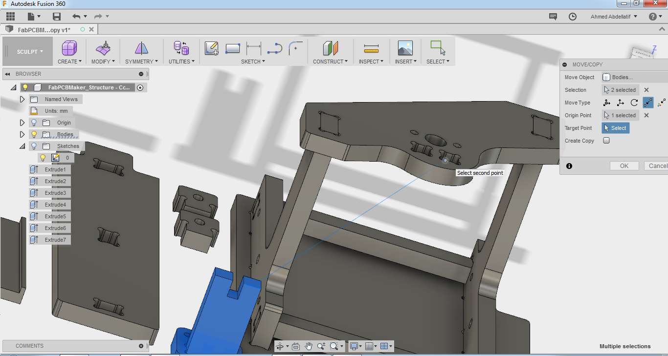
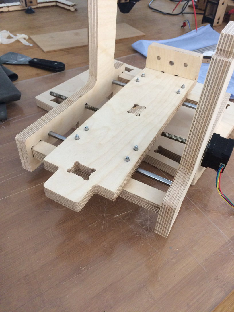
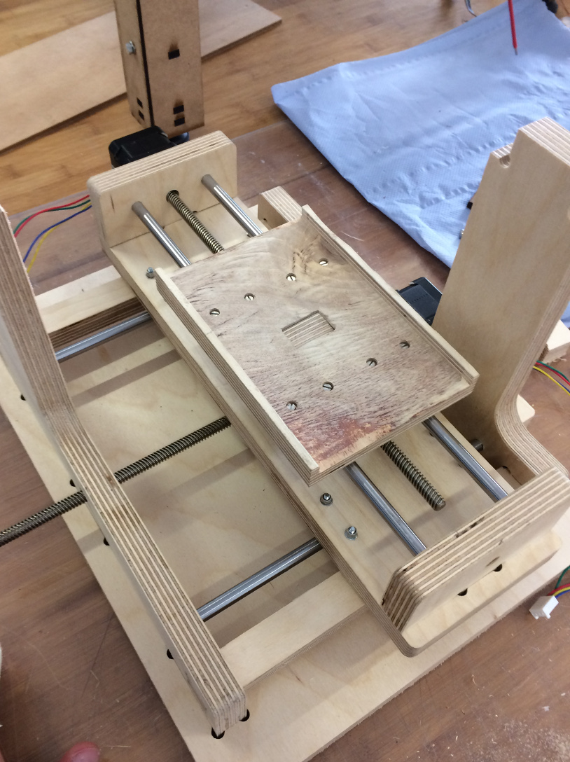
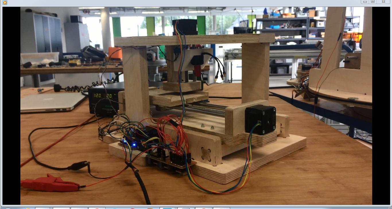
Assembling
As the structure is made of wood it was really easy to assemble, I just needed a small plastic hammer to fit the joints together. There were some other tasks related to the assembling like fixing the motors to their holders and the bearings in their right place.


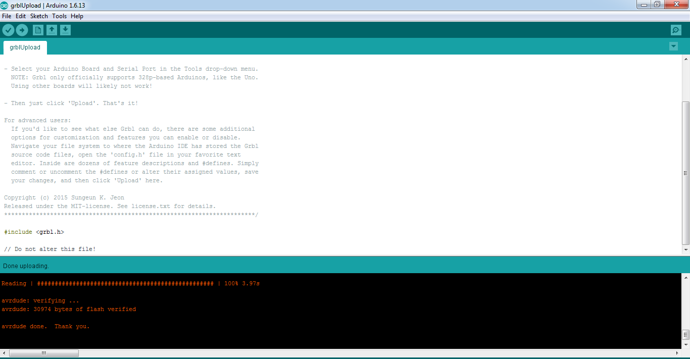
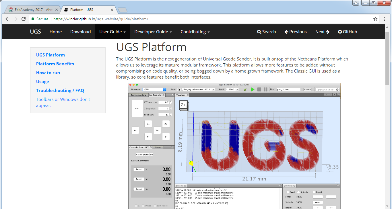
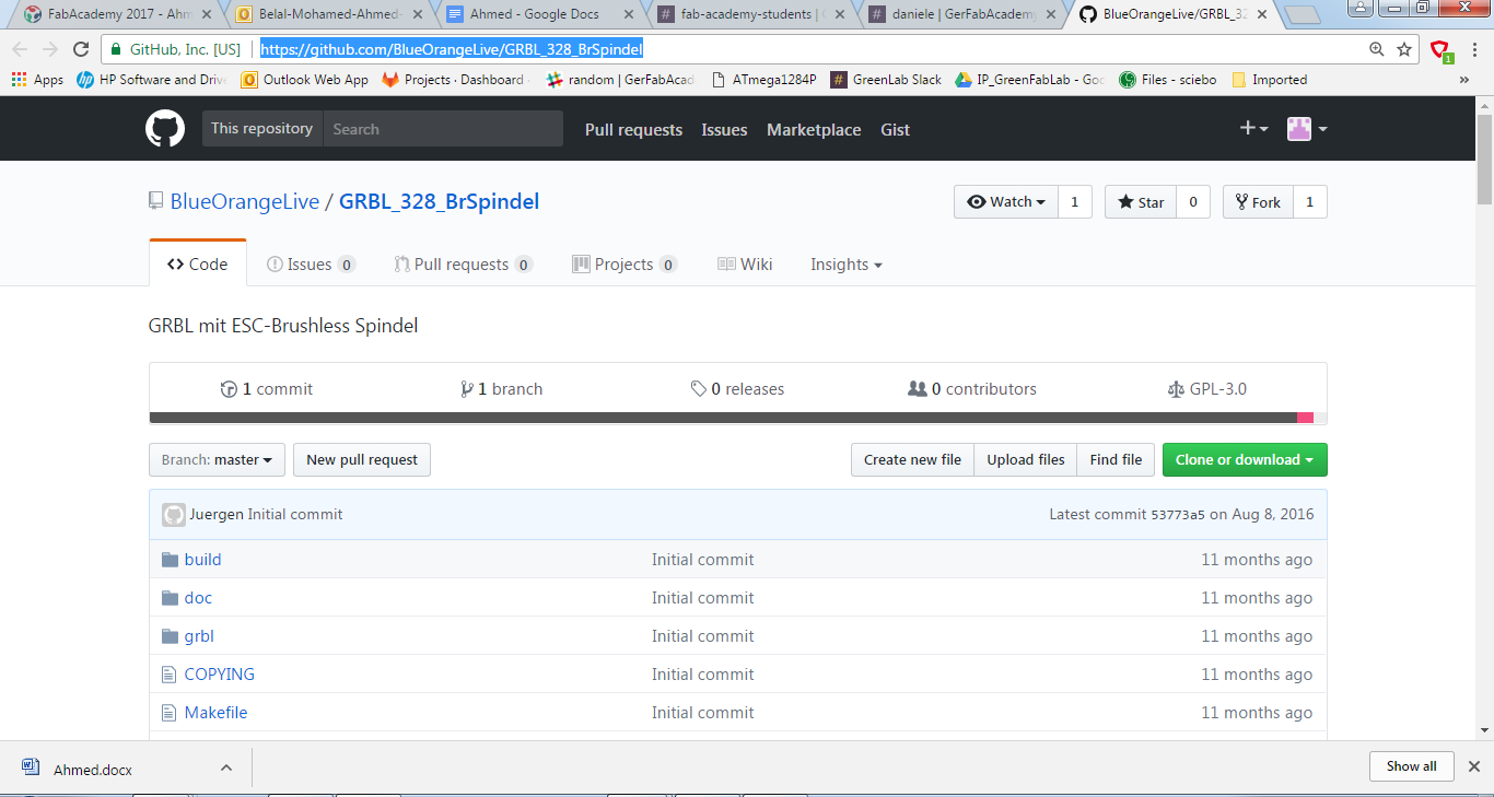
Programming
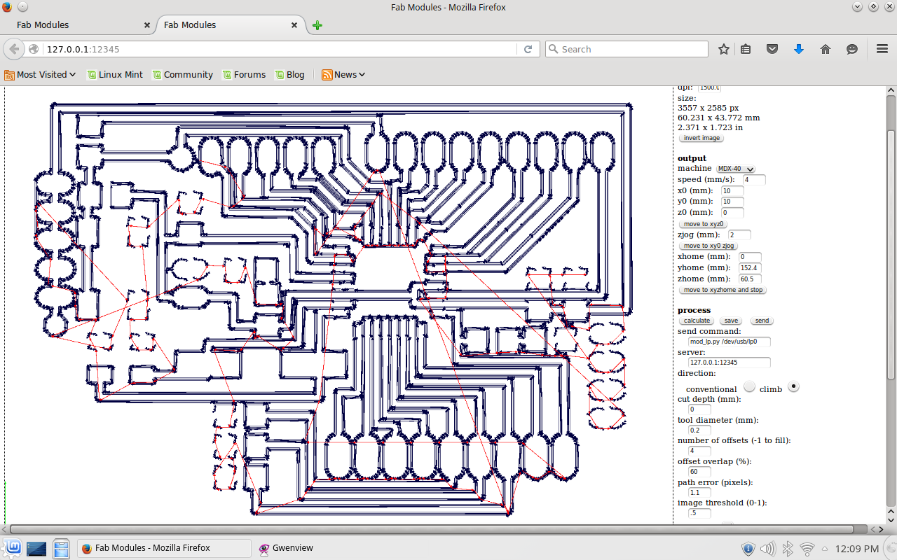
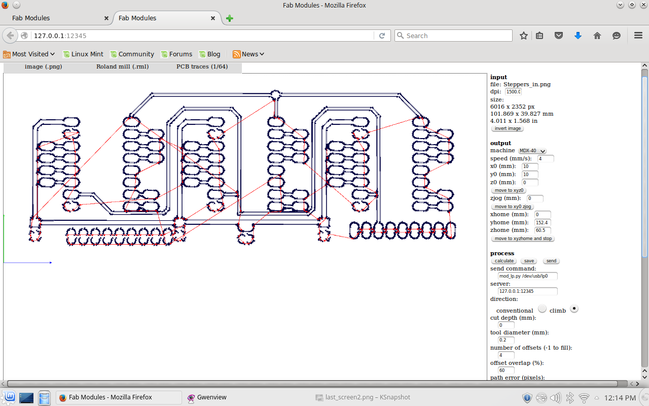
To control the machine I decided to use GRBL to send the Gcode which I generate using Fabmodules
-Here are the parameters I used:
- Input format: Image.png
- Output format: Gcodes.nc
- Process: 1/64 -->for PCB milling
- Speed: 4
- Cut depth: 0 Tool diameter: 0.1mm
- Number of offsets: 2
- Offset overlap: 60

Here are the final settings that I used
$1 = 25    (Step idle delay, milliseconds)
$2 = 0    (Step pulse invert, mask)
$3 = 0    (Step direction invert, mask)
$4 = 0    (Invert step enable pin, boolean)
$5 = 0    (Invert limit pins, boolean)
$6 = 0    (Invert probe pin, boolean)
$10 = 1    (Status report options, mask)
$11 = 0.010    (Junction deviation, millimeters)
$12 = 0.002    (Arc tolerance, millimeters)
$13 = 0    (Report in inches, boolean)
$20 = 0    (Soft limits enable, boolean)
$21 = 1    (Hard limits enable, boolean)
$22 = 1    (Homing cycle enable, boolean)
$23 = 0    (Homing direction invert, mask)
$24 = 250.000    (Homing locate feed rate, mm/min)
$25 = 500.000    (Homing search seek rate, mm/min)
$26 = 250    (Homing switch debounce delay, milliseconds)
$27 = 3.000    (Homing switch pull-off distance, millimeters)
$30 = 1000    (Maximum spindle speed, RPM)
$31 = 0    (Minimum spindle speed, RPM)
$32 = 0    (Laser-mode enable, boolean)
$100 = 400.000    (X-axis travel resolution, step/mm)
$101 = 400.000    (Y-axis travel resolution, step/mm)
$102 = 400.000    (Z-axis travel resolution, step/mm)
$110 = 500.000    (X-axis maximum rate, mm/min)
$111 = 500.000    (Y-axis maximum rate, mm/min)
$112 = 500.000    (Z-axis maximum rate, mm/min)
$120 = 10.000    (X-axis acceleration, mm/sec^2)
$121 = 10.000    (Y-axis acceleration, mm/sec^2)
$122 = 10.000    (Z-axis acceleration, mm/sec^2)
$130 = 200.000    (X-axis maximum travel, millimeters)
$131 = 200.000    (Y-axis maximum travel, millimeters)
$132 = 200.000    (Z-axis maximum travel, millimeters)
Testing
To evaluate how good is my machine I set a challenge which is milling a working FabISP. In this section I am documenting the testing process of my machine.
- Next I connected the spindle, attached 0.1mm tool to it and tried to engrave something on a piece of MDF
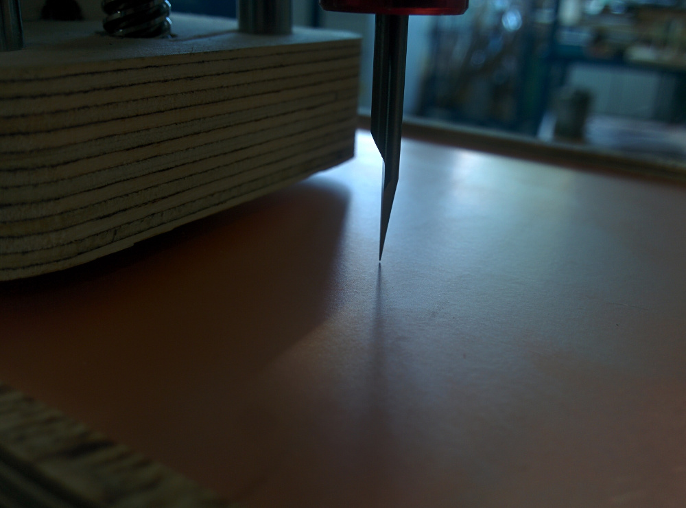
- I replaced the piece of wood with a copper plate and gave it a shot
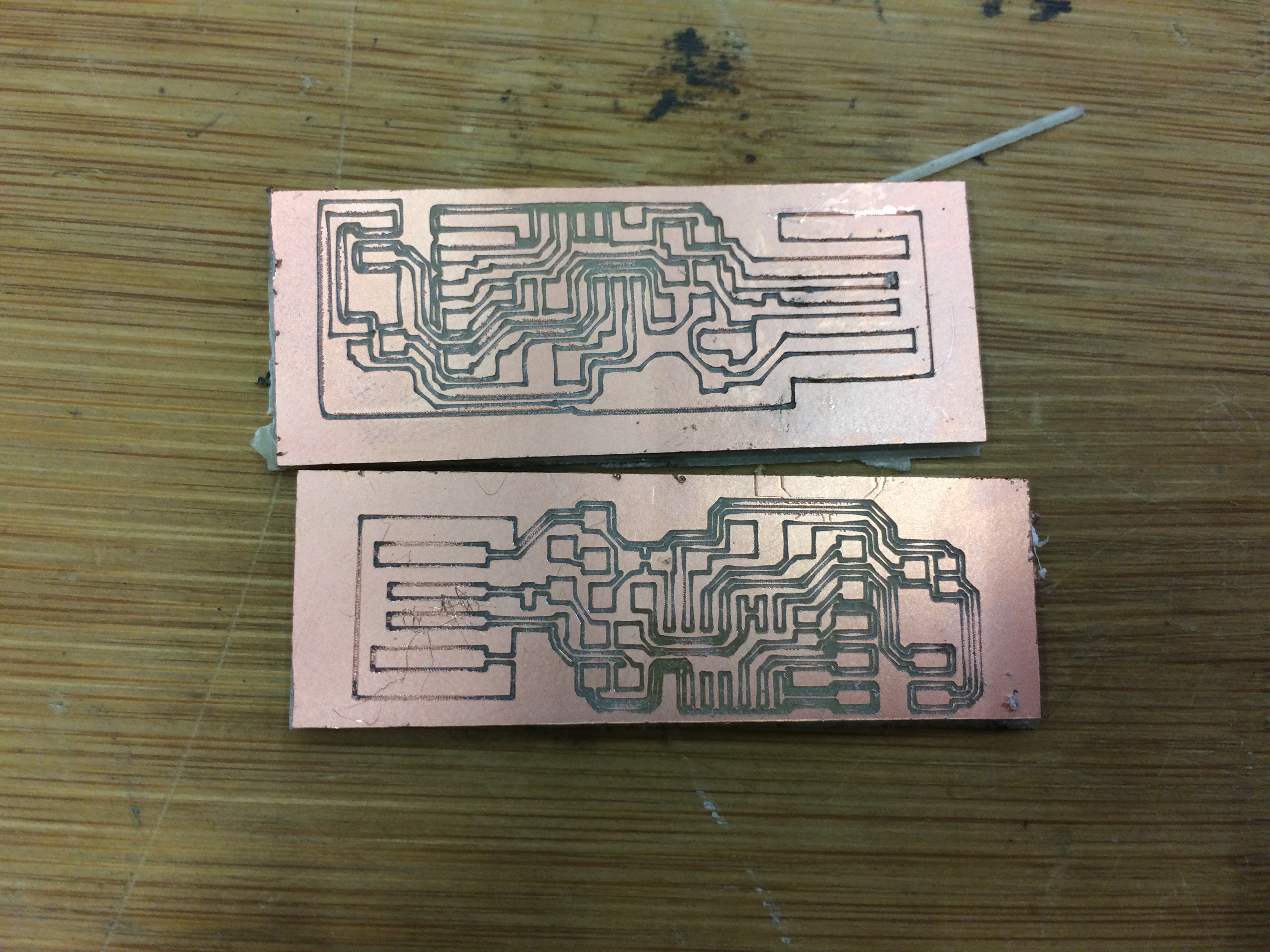
- After some trials and adjustments of the Z height I got to this result.
I found out 3 important issues
- By looking under the microscope I saw that the tool was more of scratching than engraving so I decided to change to a 0.2mm drilling one
- The second thing was that the feedrate was too high this can be seen as the straight lines were no longer straight.
- The milled boards were mirrored. This meant that one of the axes X or Y had to be flipped but I just decided to flip the image and continue testing as my focus was on the quality of milling itself

.jpg)
Final Product
After all the trials and errors I found the correct settings for the machine to work properly. Here are all the tips
- The 0.2mm tool is better than 0.1mm
- Fixing the tool properly to the motor is crucial. The screws of the collar have to be tightened gently the perfect way would be to use a tool with 0.1 Newton force.
- The cutting speed should be less than 2
- Finding the correct Z height is also crucial the quality and the thickness of the traces depend on it

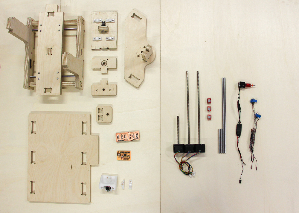
Machine specifications
- 100x160x50mm working area
- 0.0025mm theorethical resolution (0.04mm realistic)
- 18mm plywood CNC milled frame
- POM bearings and motor holder
- brushless spindle motor
- 3 x Pololu A4988
- 3 x Nema 17 threaded rod stepper motors
- 8mm linear rods
Bill of Materials
- 18mm plywood
- 3 x Nema 17 threaded rod stepper motors
- Brushless motor
- POM()
- 8mm linear rods
- 3 x Pololu A4988
- Tool collar
- M3 Bolts, Nuts and washers
- End stops