11th Assignment
Input Devices
This assignment is about Measuring something: adding a sensor to a microcontroller board that you have designed and read it.
Light Sensor
In this assignment I decided that I need a light sensor to work with my SmartCurtain to make it easy for the user to adjust the brightness in the room.
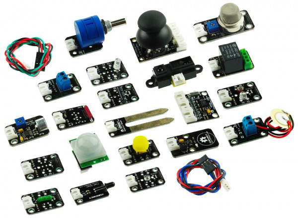
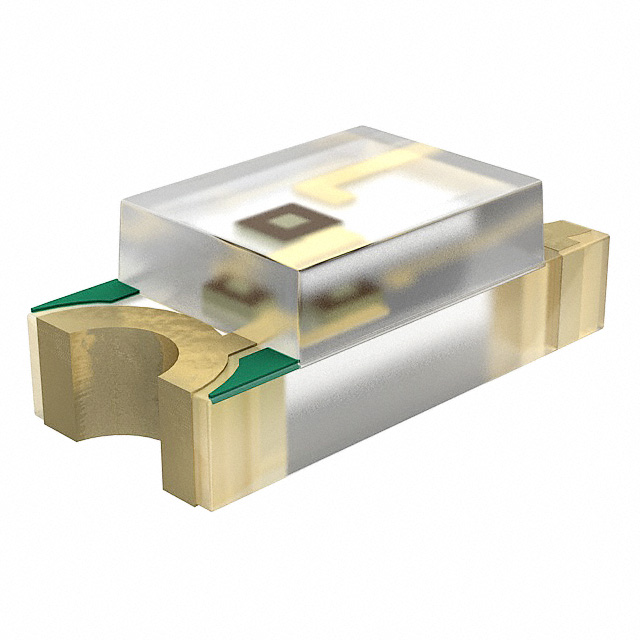
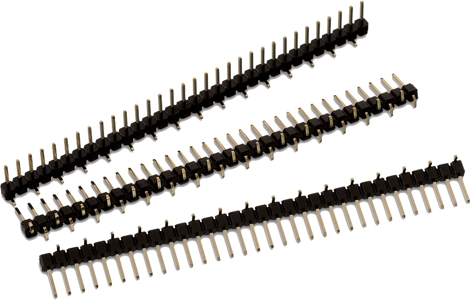
The inventory offered 3 types of phototransistors I decided on the second one (1080-1380-1-ND from DigiKey) that looked a lot like the PT15-21B / TR8 but with a transparent coating instead of black.
from the datasheet I've known that that this phottransistor acts as a variable resistor
so that you need a fixed resistance and the pin between these two resistors to collect the potential difference and thus read the sensor data.
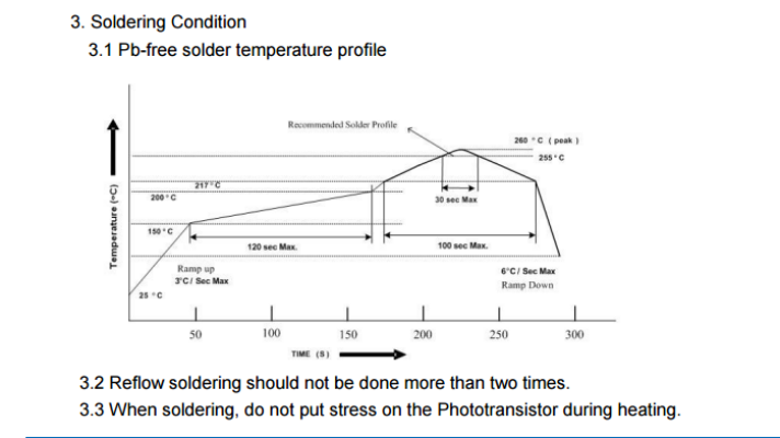
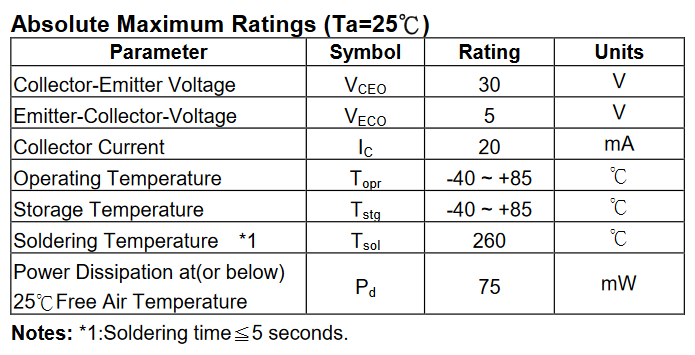
Soldering Specifications
What benefited me most about this datasheet were the soldering conditions.
I've known why my first sensor were not working proberly.
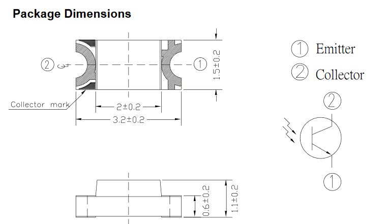
Differentiating between emitter and collector
another important thing I've found in the datasheet is how to know the emitter and collector which was confusing to me at first.
Knowing the sensor's extremes
I also made sure about its operating voltage from this table.
you can download the full datasheet from HERE.
Used Libraries
I used Eagle to design the PCB.
the used libraries in this PCB were:-
fab.lbr
ng.lbr
I also used another library for the pin headers of the FTDI because In the lab we are using
another package than the regular one used in FAB library.
EAGLE-BOARD-TO-BOARD_CONNECTORS-rev16c.lbr when adding these pins from the library search for "61000618221".
Hello.Light.45
I decided as a beggining I should work with the same PCB Niel shared with us. which is hello light 45 in this lecture
because I wanted to play it safe and it would be easier.
then I will design my own one.
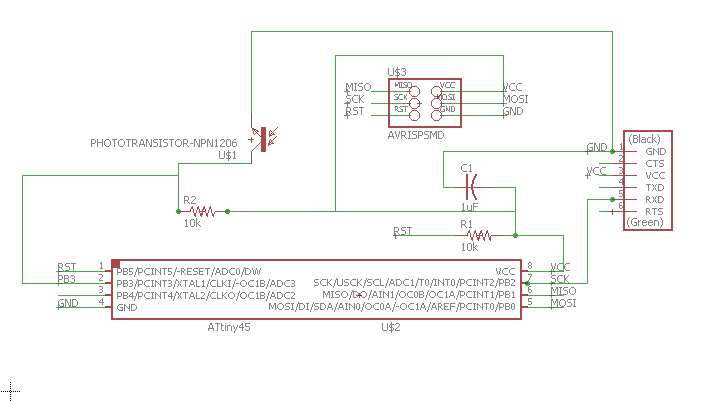
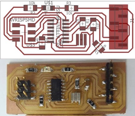
Hello.Light.45 Schematic
I worked in designing this PCB the same way I made the design in Electronics Design Assignment
At first I designed the schematic of the Hello.light.45 by adding the components in the schematic view and connecting them.
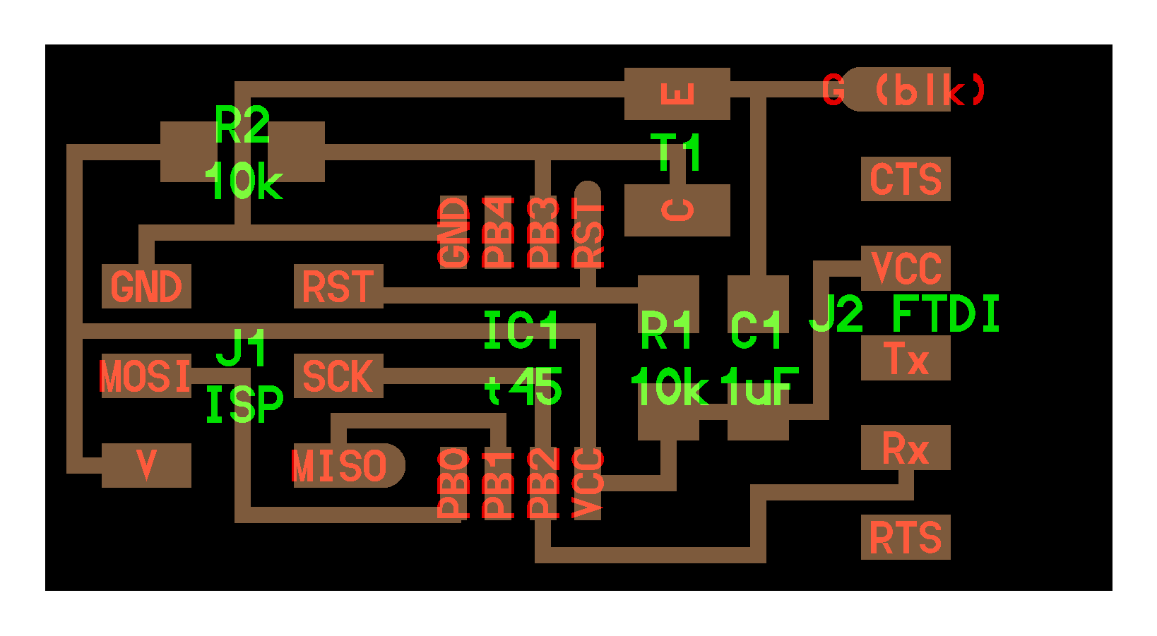
Switching to board layout
that's how it looked like after arranging the components somehow like Niel's one.
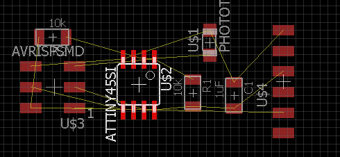
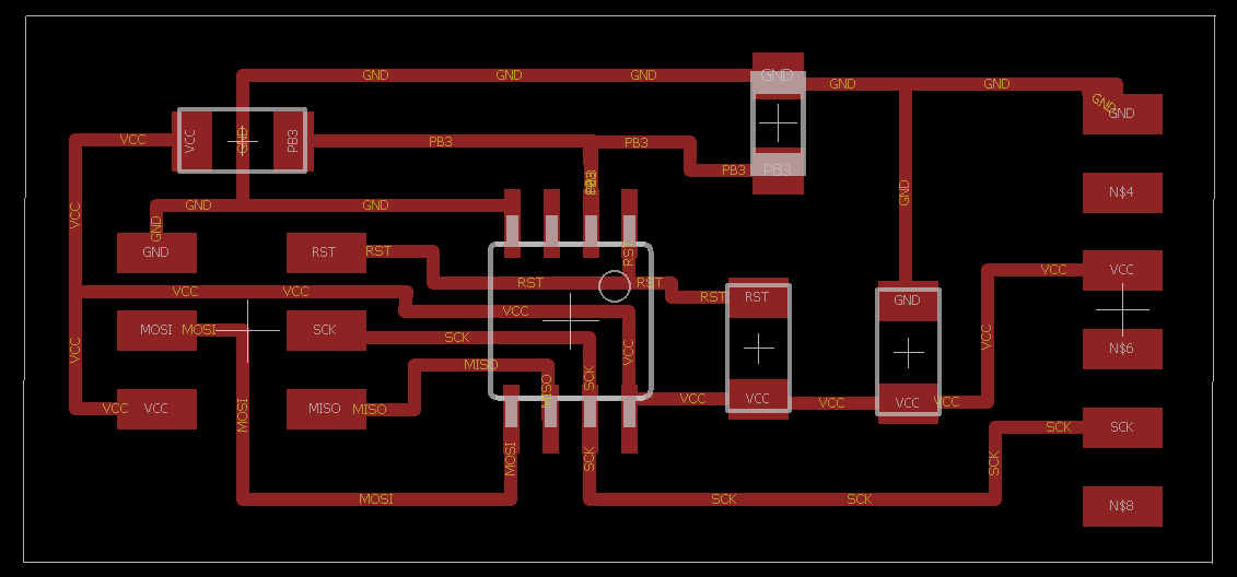
Making the connections
that's how it looked like after connecting the components somehow like Niel's one.
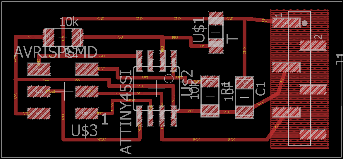
Changing the FTDI headers
then I changed the FTDI headers to the available type in the lab.
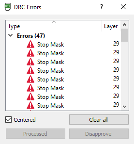
DRC (Design Rule Check)
After making DRC I found no errors, just stop masks that could be neglected.
Exporting
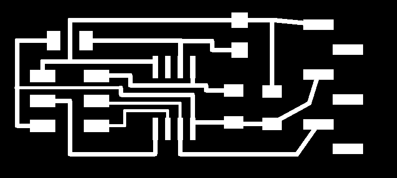
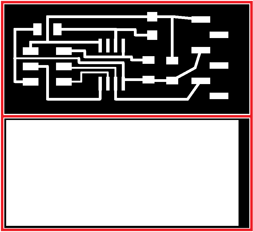
Then I needed to export both the traces and the outline, here it's how it looked after exporting as monochrome and with 500 dpi and after editing the outline
as explained in the electronics design assignment.
Downloadable links for the traces and the outline.
Traces.png
Outline.png
Downloadable Eagle Files
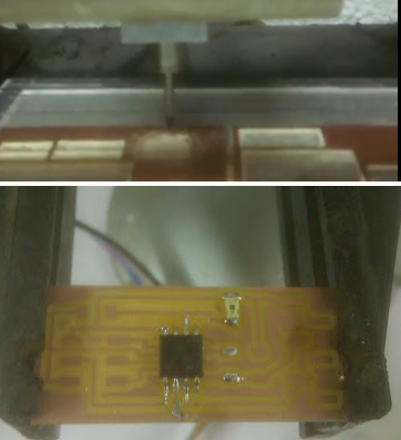
Machining and soldering
I used the same way of production used in electronics production assignment
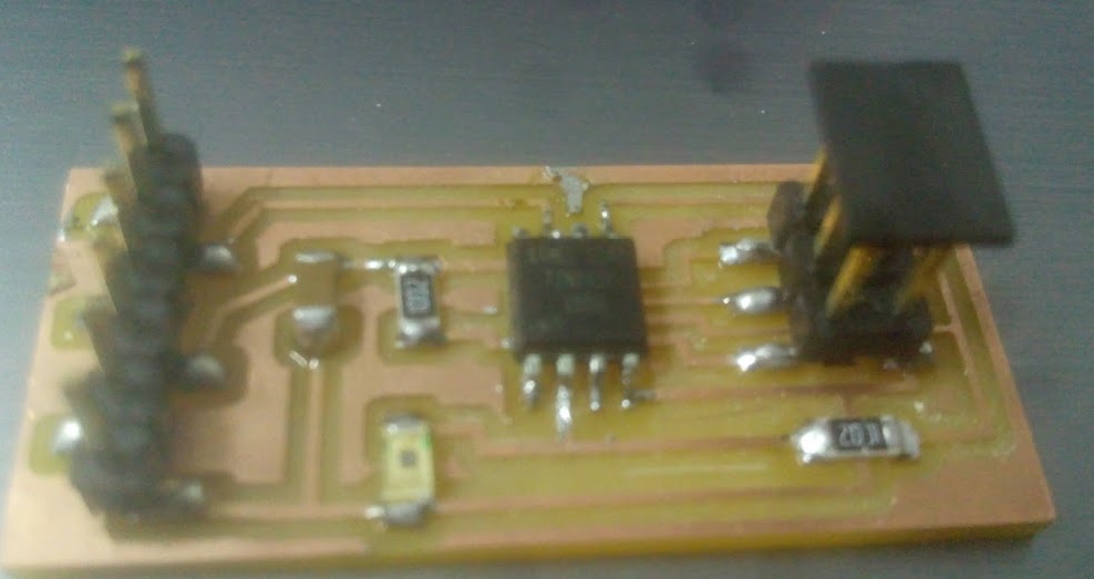
The final product
Here it how it looks after soldering
The Coding Phase
I used Niels Code and saw how it worked and uploaded it using Arduino as this tutorial explains.
It can be uploaded using FabISP like the last step in embedded programming assignment.
In the edited code I described briefly the code lines and what it did.
if you want to know more details you You can check the embedded programming assignment to see:-
how I configured the pins (Input & Output pins).
and how I set the clock divider to be /1.
and which registers are responsible of tuning the internal oscillator if you want to tune it.
In the following steps I will explain the remaining of the lines of the code which weren't explained in details in the embedded programming or the comments in the code.
Analog to Digital Converter
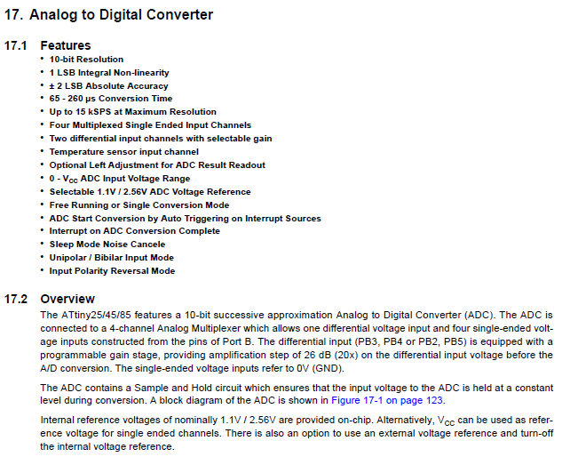
From Attiny 45 datasheet section 17 I've found the main features of the analog to digital converter.
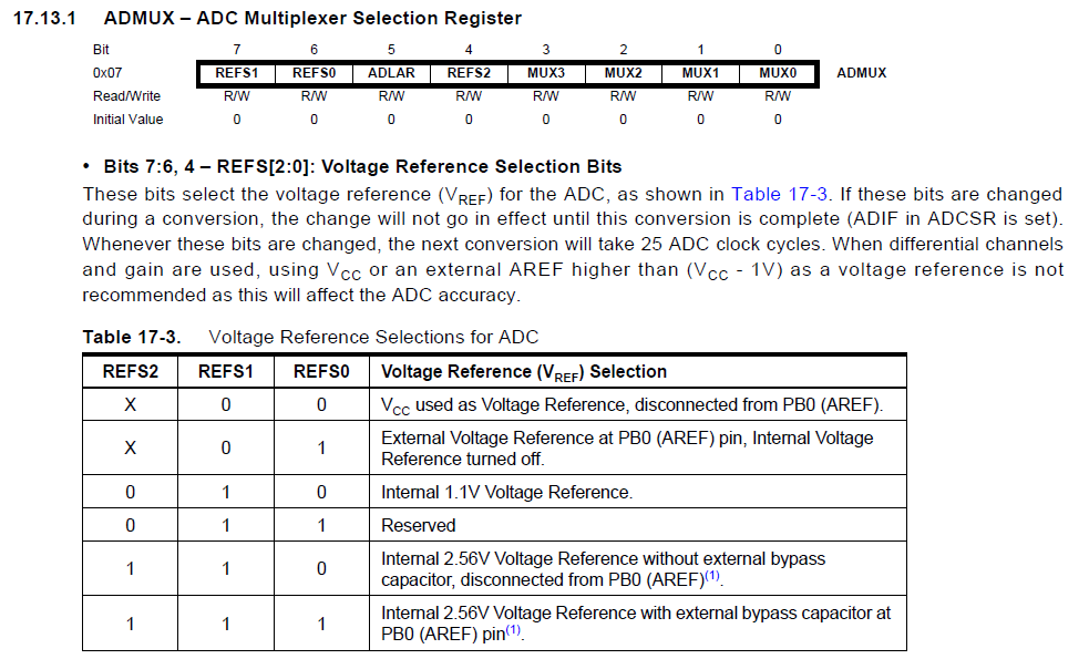
ADMUX ADC Multiplexer Selection Register
(Voltage Reference)
Bits 7, 6 and 4 REFS(0,1,2)select the voltage reference (VREF) for the ADC. to select VCC as voltage reference I selected these register to be 0
ADMUX = (0 << REFS2) | (0 << REFS1) | (0 << REFS0) // Vcc ref
ADLAR: ADC Left Adjust Result
The ADLAR bit affects the presentation of the ADC conversion result in the ADC Data Register. Write one to ADLAR to left adjust the result. Otherwise, the result is right adjusted.
| (0 << ADLAR) // right adjust
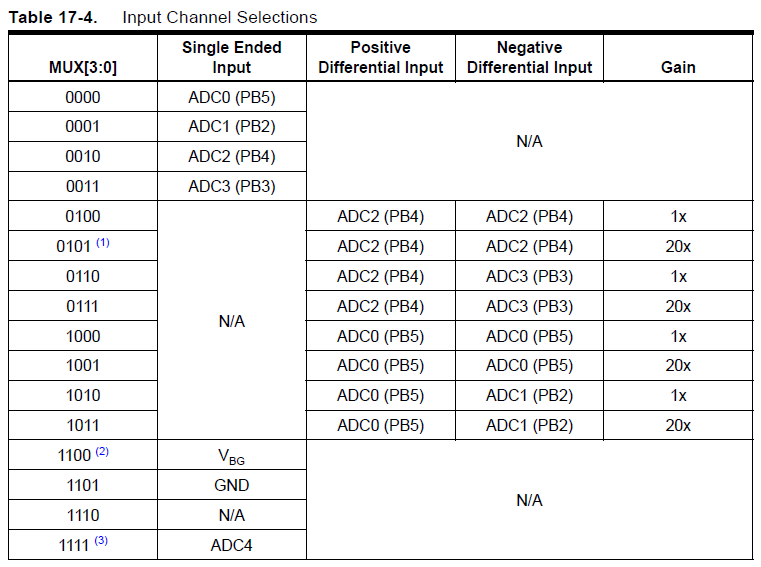
Input Channel Selection
(MUX Bits)
The value of these bits selects which combination of analog inputs are connected to the ADC.
In case of differential
input (ADC0 - ADC1 or ADC2 - ADC3), gain selection is also made with these bits.
Selecting ADC2 or ADC0 as
both inputs to the differential gain stage enables offset measurements.
to select PB3 as an input I chose these values from the table.
| (0 << MUX3) | (0 << MUX2) | (1 << MUX1) | (1 << MUX0); // ADC3
ADC Control and Status Register A
ADCSRA
ADEN
ADC Enable
From section 17.13.2 talking about ADEN bit:-
Writing this bit to one enables the ADC. By writing it to zero, the ADC is turned off.
Turning the ADC off while a conversion
is in progress, will terminate this conversion.
so it was enabled by by entering 1 value.
ADCSRA = (1 << ADEN) // enable
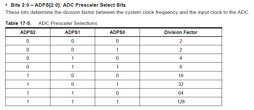
ADC Prescaler Select Bits
ADPS
These bits determine the division factor between the system clock frequency and the input clock to the ADC.
as the internal oscillator is 8MHz and I need between 50 and 200 KHz.
"By default, the successive approximation circuitry requires an input clock frequency between 50 kHz and 200 kHz
to get maximum resolution." -from the datasheet section 17.5.- so I need devision factor 128 or 64 but 128 is better.
| (1 << ADPS2) | (1 << ADPS1) | (1 << ADPS0); // prescaler /128
The total setup of ADC
These bits determine the division factor between the system clock frequency and the input clock to the ADC.
as the internal oscillator is 8MHz and I need between 50 and 200 KHz.
"By default, the successive approximation circuitry requires an input clock frequency between 50 kHz and 200 kHz
to get maximum resolution." -from the datasheet section 17.5.- so I need devision factor 128 or 64 but 128 is better.
// init A/D
   //
   ADMUX = (0 << REFS2) | (0 << REFS1) | (0 << REFS0) // Vcc ref
      | (0 << ADLAR) // right adjust
      | (0 << MUX3) | (0 << MUX2) | (1 << MUX1) | (1 << MUX0); // ADC3 PB3
   ADCSRA = (1 << ADEN) // enable
      | (1 << ADPS2) | (1 << ADPS1) | (1 << ADPS0); // prescaler /128
The Coding Phase
I also used the same Python code to make the outputs of this code readable.
I used these orders in the picture in command prompt (cmd) to get the python code working.
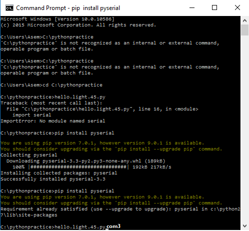
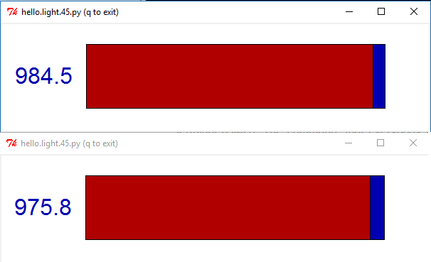
It's working!
Then I got it working with a very high sensitivity, this difference was by just changing the orientation of the sensor board a little.
A new board with attiny 44
I made another one with attiny 44 and used a 20 MHz oscillator, to be programmed by Arduino.C and added TX and RX to it, as using external oscillator is better than the internal which is +-10% inaccurate.
it will be used in networking assignment and in the final project.
I had a problem in the reading of the phototransistor so I tried to add a capacitor after the phototransistor but it didn't stabilize it ,
after some searching and looking into the datasheet
of the phototransistor I've found that the phototransistor was broken because it couldn't be soldered more than twice (I soldered it about four times because I got confused about the polarity),
so after changing the phototransistor it was working nice by adding a zero ohm resistor in capacitor's place (to make it like a bridge).
Downloadable files
in the networking assignment the used code with Attiny 44 was Arduino.C
Testing the Attiny44
This is the code used to test the serial communication with the board.