"
Fourth Assignment
Electronics Production
This assignment is about:-
Making an in-circuit programmer by milling the PCB

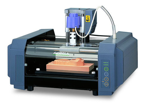
I started working with my friend Mahmoud Alaa to help each other learn how the Roland Modela MDX-20 works, we passed through many steps but we didn't reach the final results till now; as the end mill broken mid-mill and we didn't have another one.
Once we reach any further results it will be updated on this page.
The First step
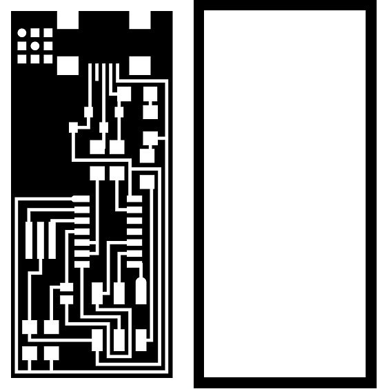
Getting the PNGs
I got the PNGs of the traces and the cutout from Here
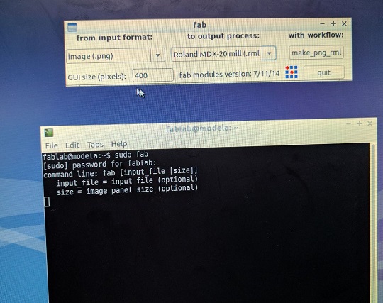
Fab modules
I opened fab modules using the terminal then typing sudo fab then typing the password of the Modela
Then I selected converting from PNG to Roland MDX-20
then I selected make_png_rml
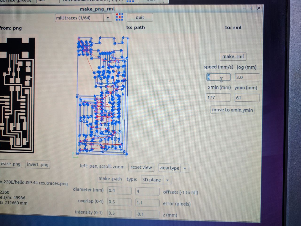
Then I loaded the PNG of the traces then selected the option of mill traces (1/64)
I left the options to be as the standards
and repositioned the end mill tip to be at the right place for milling by changing the X and Y position.
Then Pressing Make Path
Then Make rml
Then Send it!
Attaching the end mill
There are two kinds of the end mills used while making a PCB using the modela:
one of them is for milling the traces and the other one is for cutting out the board
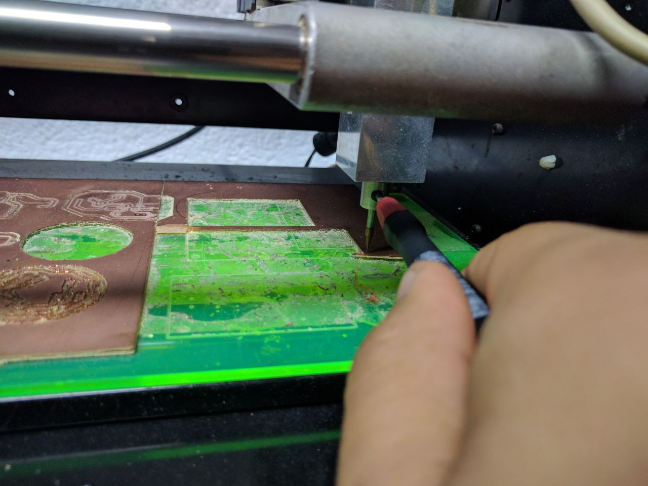
after changing the end mill you have to make the tip of the end mill touches the surface of the PCB (I used RF-1 type) by loosing the set screw after making the end mill too close to the PCB.
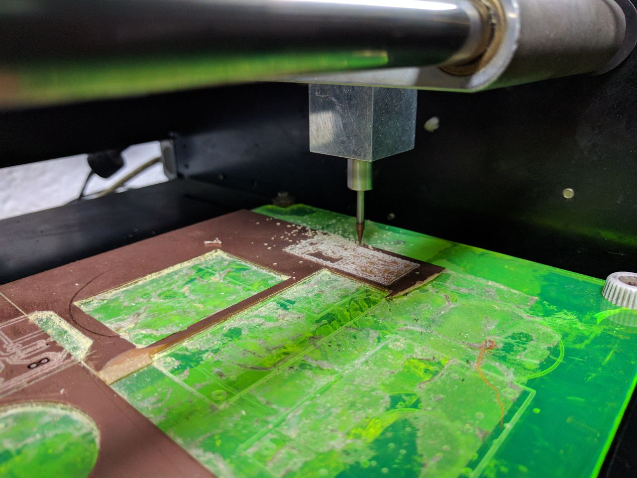
Beggining the Process
Then I pressed begin milling then waited the results.
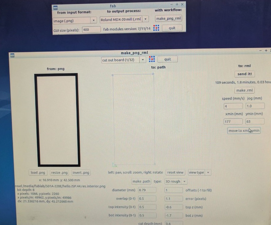
Cutting Board Out
After finishing milling traces we changed the end mill, loaded the second picture of cutting the board and selected the default options for (cut out board (1/32))
then we sent it like the previous step and the same position.
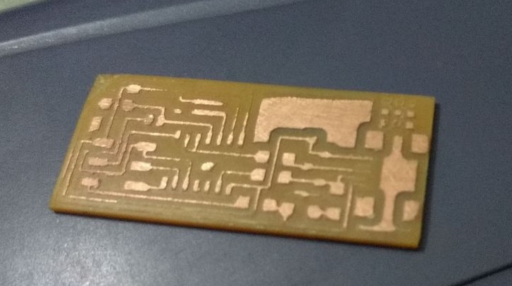
The final results of the first trial
After extracting the PCB some traces was not ok and it was not satisfying results so whe have tried other options but the end mill broke and it was the last one, we've ordered another one and we are waiting it to be shipped to our fab lab.
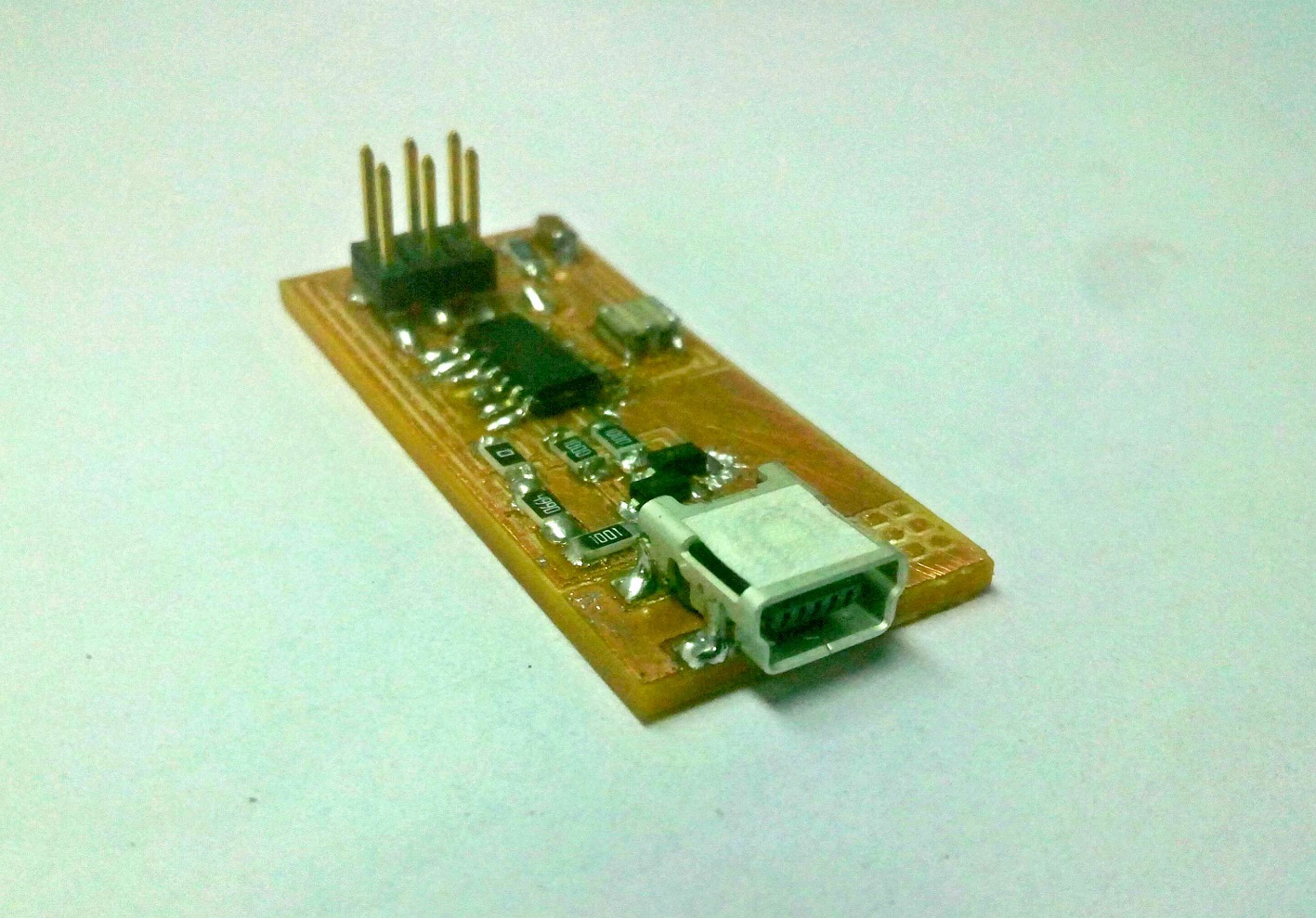
The final results of the second trial
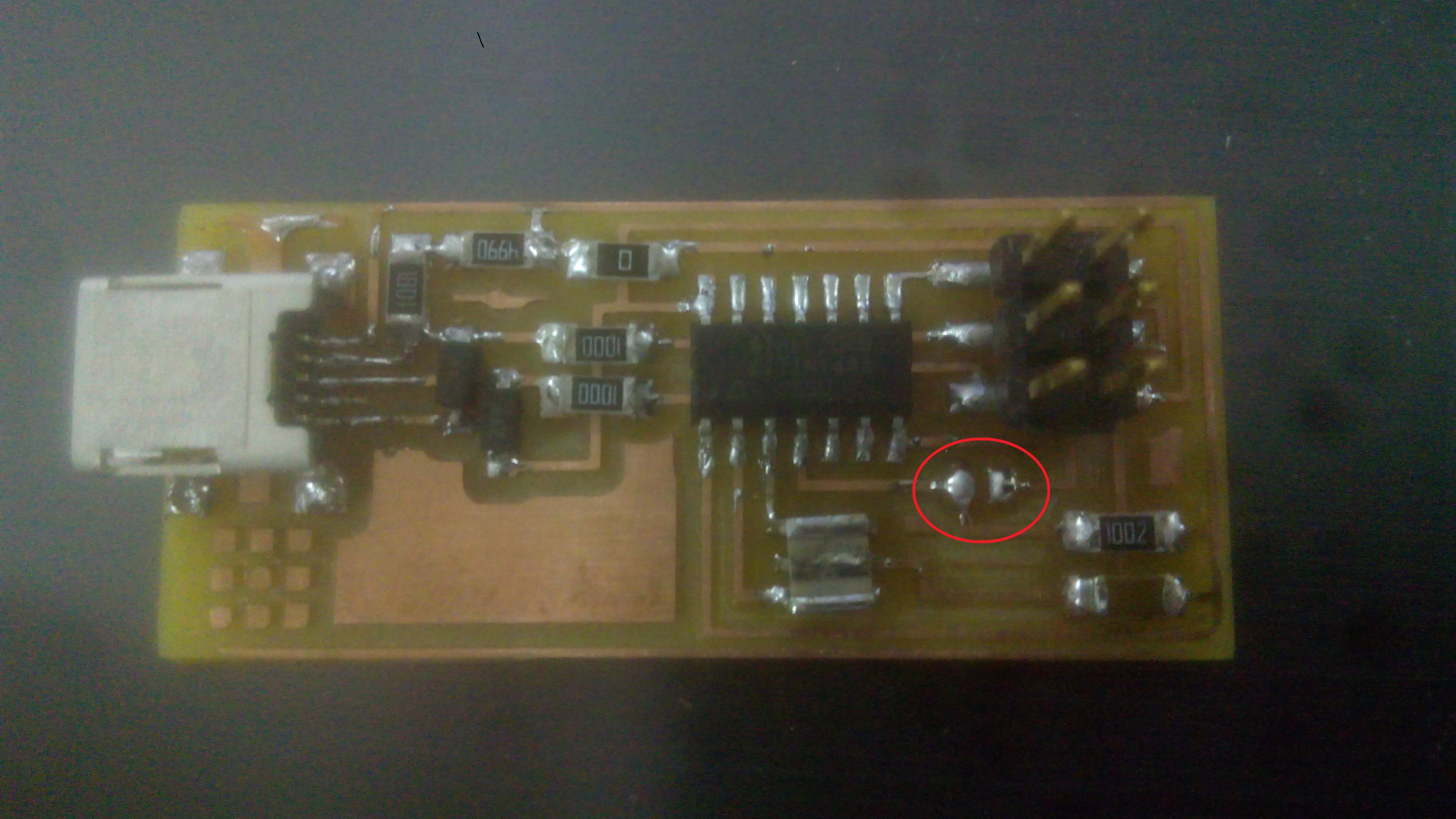
After getting the new end mills I have made another PCB and soldered the components to it and here it is how it looked after soldering.
The final results of the third trial
I got my FabISP broken, so I got to make a new one

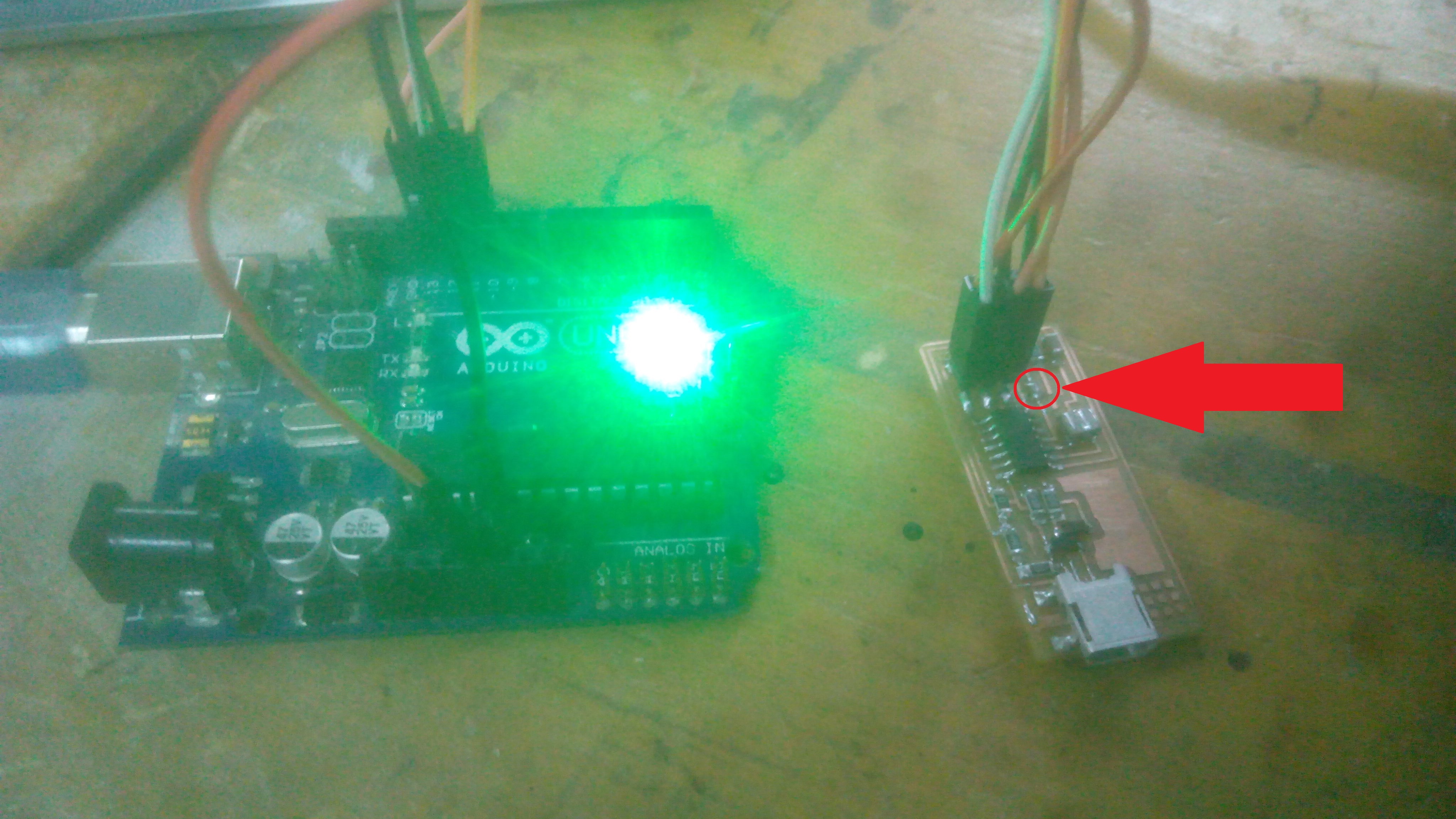
Programming The FabISP
In programming the FabISP I used an Arduino as an another ISP.
all I have to do is connecting the pins 10,11,12,13,Vcc and GND on Arduino to RST, MISO, MOSI, SCK, Vcc and GND on the fab ISP while having the jumper on the FabISP connected.
you can find all the details of using Arduino as ISP from HERE.
Download the required files
In order to program the fabISP you have to install the following:-
1-WinAVR.
2-Adafruit USBTinyISP Drivers.
3-FabISP Frimware.
Editing the make file
#AVRDUDE = avrdude -c usbtiny -p $(DEVICE) # edit this line for your programmer
AVRDUDE = avrdude -c stk500v1 -b19200 -P COM3 -p $(DEVICE) # edit this line for your programmer
Using cmd
the following steps are done in cmd.
Opening the folder path then make clean then make hex
.png)
make fuse
.png)
make program
.png)
After programming the FabISP
you have to disconnect the jumper.
enjoy programming your boards!