"
Eighth Assignment
Embedded Programming
This Excercise was about:-
1-Reading a micro-controller data sheet
2-Programming the board to do something, with as many different programming languages and programming environments as possible.
3-Extra credit: experiment with other architectures
The Used Board
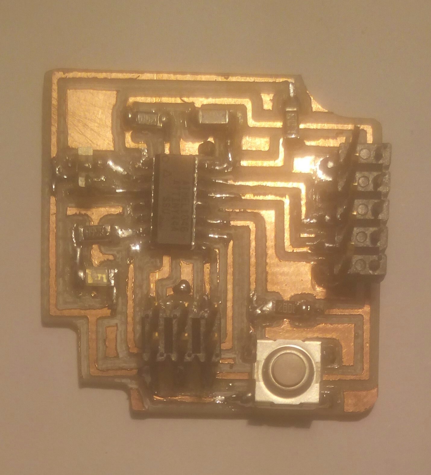
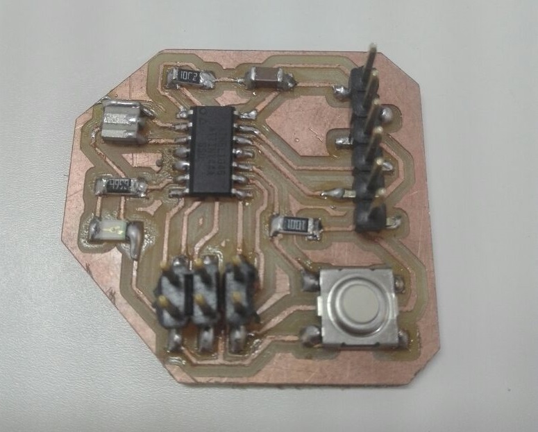
In this assignment I used the Hello-Echo board which I made in this task.
I wanted to make it blink with a delay like the most basic example in the arduino code blink.
Good Tutorials
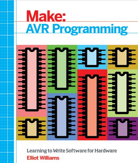
One of the best books I've found on the Internet was Elliot William's book"Make: AVR PROGRAMMING". which you can download from Here
Using Arduino As an ISP
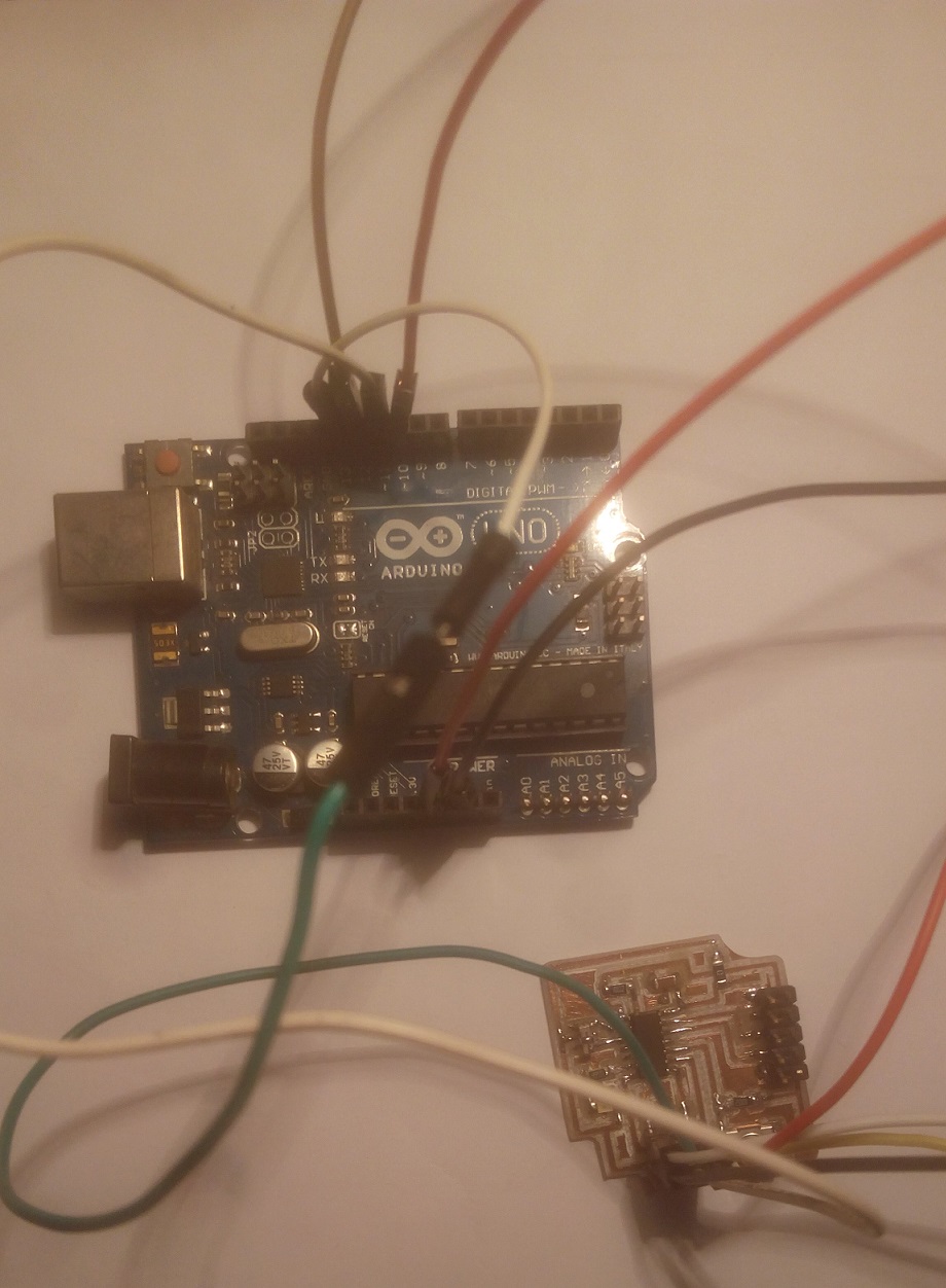
As I have some problems with my FABISP till this moment so I wanted to try to program my board another way.
one of the easiest
ways to upload the code to the AVR microcontroller was by using the Arduino which is available almost anywhere and for sure I have more than one in my collection.
It was mentioned in the book the ways to use it but then I found an easier way to Use it as a programmer which you will find in this Link.
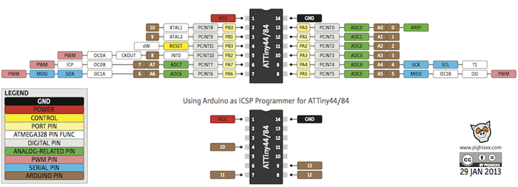
The Pins map
In this step I had to use the datasheet.
As William said in his book -Make: AVR PROGRAMMING-
The trick is to approach the datasheet like a reference
book rather than a novel. If you’re learning a new foreign
language, you don’t start by opening up a
dictionary to page one and reading onward. A
dictionary is most useful when you already have a
basic idea of how the language works, but you’ve just
forgotten how to say “lemur” in Portuguese."
so I had to got through there to know only the pins of the micro controller and which pins I had to connect to the Arduino.
then I've found this useful picture
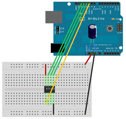
Connecting the Arduino and The Hello-echo
then I connected the Arduino and the hello echo as the tutorial suggests and as the previous picture says.
Uploading the code
to upload the code I had to select the ISP code from examples and burn it to the arduino uno.
then I had to install the package of the ATTinys where you can find in thisLink to make me able to upload to Attiny44 as a board.
.png)
The Code
the first code I uploaded to the board was the button code of the Arduino, All I had to modify is the Pin numbers to make the LED assigned to pin #7 and the Button to pin #3 as I've known from the datasheet.
and to change the button state to be LOW whin it's pushed as it's connected to the ground not the VCC.
const int buttonPin = 3; // the number of the pushbutton pin
const int ledPin = 7; // the number of the LED pin

// variables will change:
int buttonState = 0; // variable for reading the pushbutton status

void setup() {
// initialize the LED pin as an output:
pinMode(ledPin, OUTPUT);
// initialize the pushbutton pin as an input:
pinMode(buttonPin, INPUT);
}
void loop() {
// read the state of the pushbutton value:
buttonState = digitalRead(buttonPin);
// check if the pushbutton is pressed.
// if it is, the buttonState is HIGH:
if (buttonState == LOW) {
// turn LED on:
digitalWrite(ledPin, HIGH);
delay (500);
digitalWrite(ledPin, LOW);
delay (500);
}
else {
// turn LED off:
digitalWrite(ledPin, LOW);
}
}
The Second Trial
If you went to the electronics design assignment you will find that I made another PCB to correct the errors I made in the previous board.
in the next steps I will try to program the board using C and I will go deeper into the datasheet.
The Second Trial
If you went to the electronics design assignment you will find that I made another PCB to correct the errors I made in the previous board.
in the next steps I will try to program the board using C and I will go deeper into the datasheet.
I combined between two functions, turning the LED ON and OFF with fading and using the button.
these tasks will be described in the next steps.
1-Fade code
In this step I wanted the led to turn ON and OFF fading (PWM), I used Neil's Code of RGB LED and edited it.
In the next steps I will show how the datasheet helped me editing the code.
The Edited Code
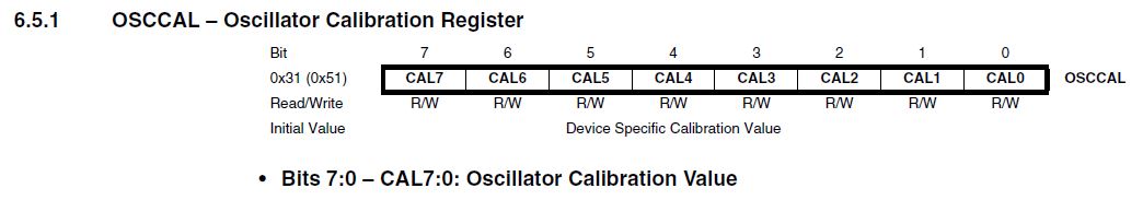
Oscillator Calibration Register
The Oscillator Calibration Register is used to trim the Calibrated Internal RC Oscillator to
remove process variations from the oscillator frequency.
Bits from 0 to 7 in the clock oscillator calibration register are used in calibration of the internal clock by editing in the EEPROM and the OSCAL which has tolerance of +-10% it can be up to 8.8 MHz or 7.2 MHz not 8 MHz accurately.
in case of using external oscillator we are not in need of calibration of the internal clock.
In This link you will find more data on how to tune the internal oscillator.
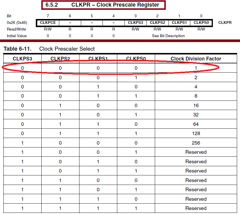
Setting the clock divider
In the datasheet from the Section 6.5.2 (clock prescale register section) I found how to set the devider to be /1
I don't need the devider to be more than that in such simple task.
The CLKPCE(Clock Prescaler Change Enable) bit (bit no.7) must be written to logic one to enable change of the CLKPS bits. The CLKPCE
bit is only updated when the other bits in CLKPR are simultaneously written to zero.
CLKPR = (1 << CLKPCE);
Bits 4,5,6 are always reserved in this register in Attiny 44 to be 0.
Bits 0,1,2,3 (Clock Prescaler Select Bits) These bits define the division factor between the selected clock source and the internal system
clock.
The division factors are given in the table.
So I had to assign value of 0 to all these bits.
CLKPR = (0 << CLKPS3) | (0 << CLKPS2) | (0 << CLKPS1) | (0 << CLKPS0);
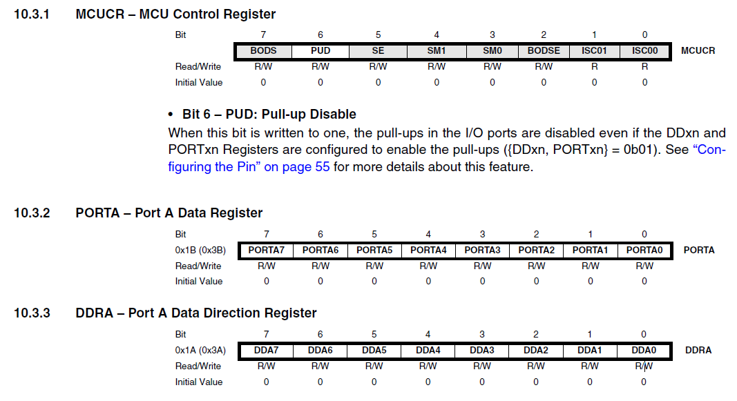
Configuring the pins
from section 10.3 in the data sheet
Each port pin consists of three register bits: DDxn, PORTxn, and PINxn. As shown in the table, the DDxn bits are accessed at the DDRx I/O address, the PORTxn bits
at the PORTx I/O address, and the PINxn bits at the PINx I/O address.
The DDxn bit in the DDRx Register selects the direction of this pin. If DDxn is written logic one,
Pxn is configured as an output pin. If DDxn is written logic zero, Pxn is configured as an input
pin.
If PORTxn is written logic one when the pin is configured as an input pin, the pull-up resistor is
activated. To switch the pull-up resistor off, PORTxn has to be written logic zero or the pin has to
be configured as an output pin. The port pins are tri-stated when reset condition becomes active,
even if no clocks are running.
If PORTxn is written logic one when the pin is configured as an output pin, the port pin is driven
high (one).
If PORTxn is written logic zero when the pin is configured as an output pin, the port
pin is driven low (zero).
these are the code line associated with making the PA7 is as output.
#define output(directions,pin) (directions |= pin)
 // set port direction for output
 #define set(port,pin) (port |= pin)
// set port pin (setting its value to 1)
 set(led_port, led);
   output(led_direction, led);
The Rest of the details are described in the code as comments.
2-Button Code
In this step I wanted to use the button to make the the PWM loop operates once when I push the button, I used Neil's Code of Switch input and edited it for my needs and added it to the previous code.
the configurations made was the same as above.
there are comments explaining the code.
here it's a video showing the final results.
The final Edited Code
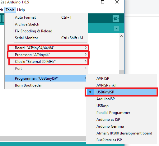
Uploading the codes
Uploading the codes was done using FabISP and Arduino IDE as the shown in the picture.
Downloadable final used Code