15th Assignment
Embedded Networking and Communications
This assignment is about Design and building a wired &/or wireless network connecting at least two processors
The used boards
In this assignment I used both the stepper driver board and the Light sensor board I've made inOutput Devices and Input Devices assignments
The idea
what I want to do in this assignment is an addition to the smart curtain which is sleep mode, as it will let the curtain open as there's low lights outside the window,
when the sunshine begins the light will increase and the curtain will close to let the fresh air into the room while sleeping until there's lights that would wake the sleepy guy up :D
The used Code on the light sensor board
I wrote a code which takes the avg of 10 readings of light and then checking if they are less than a certain amount then it means the lights are strong so it will send a number to the stepper driver board to close the curtain.
Else if that number was larger than a certain amount it means that it's dark outside, then it will send a number to the stepper driver board which will cause it to open the curtain to let the fresh air in.
View the code from HERE.
this code was made by Arduino C and uploaded by an Arduino as an ISP.
The used code on stepper driver board
the code waits a number if it's 5 it will close if it's 2 it will open.
View the code from HERE.
this code was made by embedded C and uploaded by an Arduino as an ISP.
Video for the working Codes
another update
Serial Bus
In this part of the assignment I will make a Serial Bus which will be somehow a better demonstration of what is Networking
The assignment breakdown
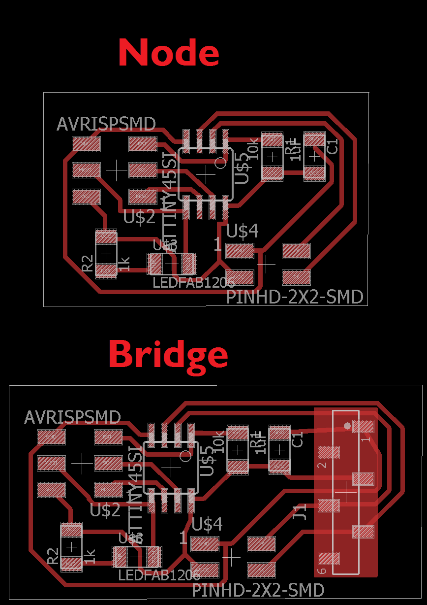
There are two boards, node (two nodes) and bridge.
The only difference is that the bridge board has FTDI pin headers connected on the bus to allow the computer to communicate with the boards.
So when the boards receive a special character that matches its identifier it toggles the led and send to the computer its name.
this can be generalized to be a talking system between the boards, which means when one board calls another board, that board only responds and the other don't which will be useful in many ways ,
that's the importance of making addressing in the code.
The Schematics
I redrawed the Serial Bus boards that are available on Networking week .
the schematics are shown here in the picture

The Boards Layout
the boards are shown here in the picture
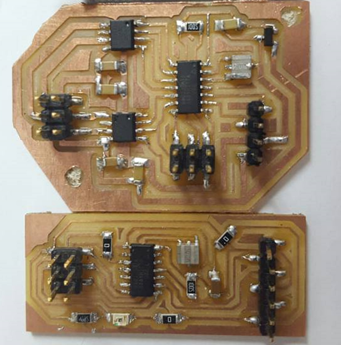
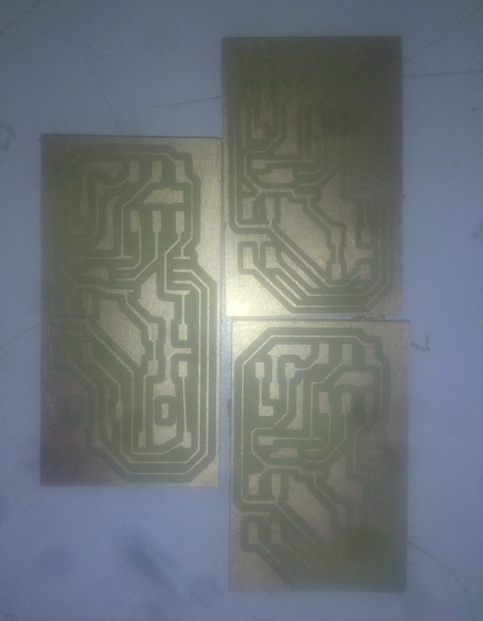
After Milling
and here it is how they looked after milling
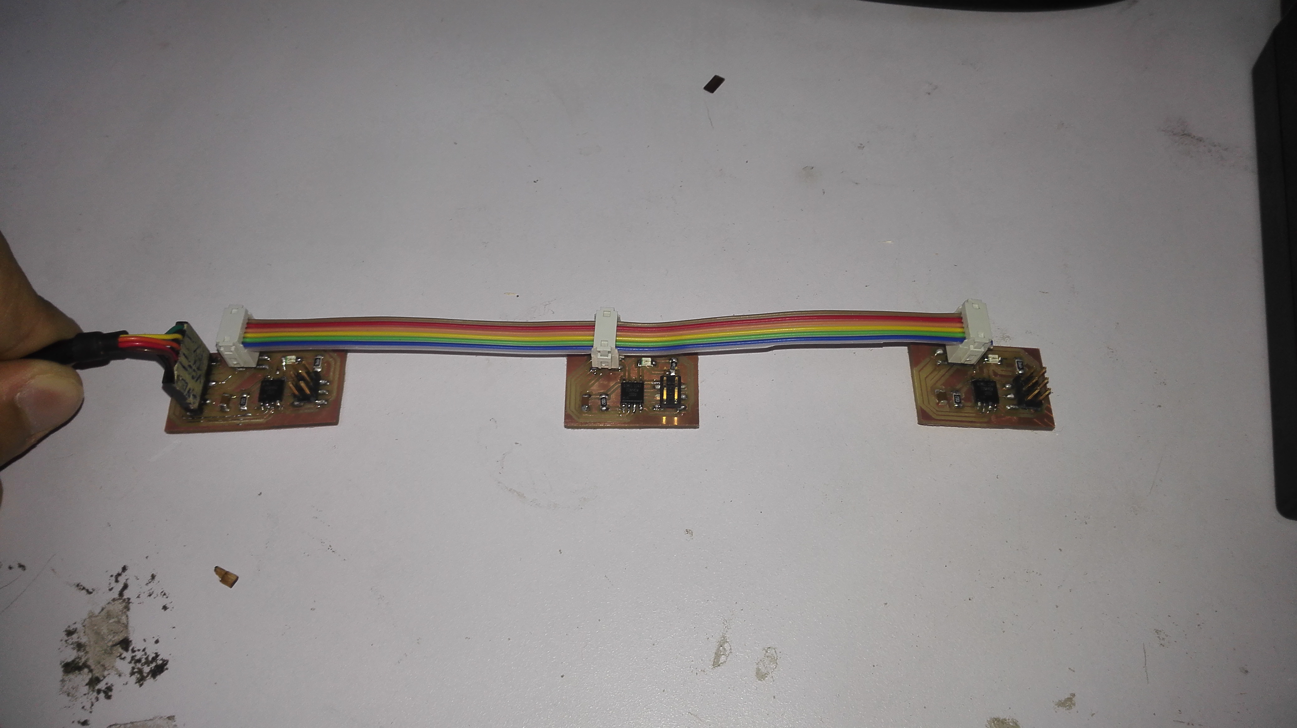
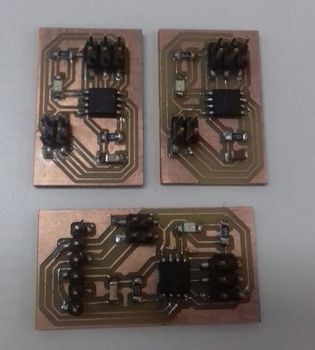
After Soldering
and here it is how they looked after soldering
The used code
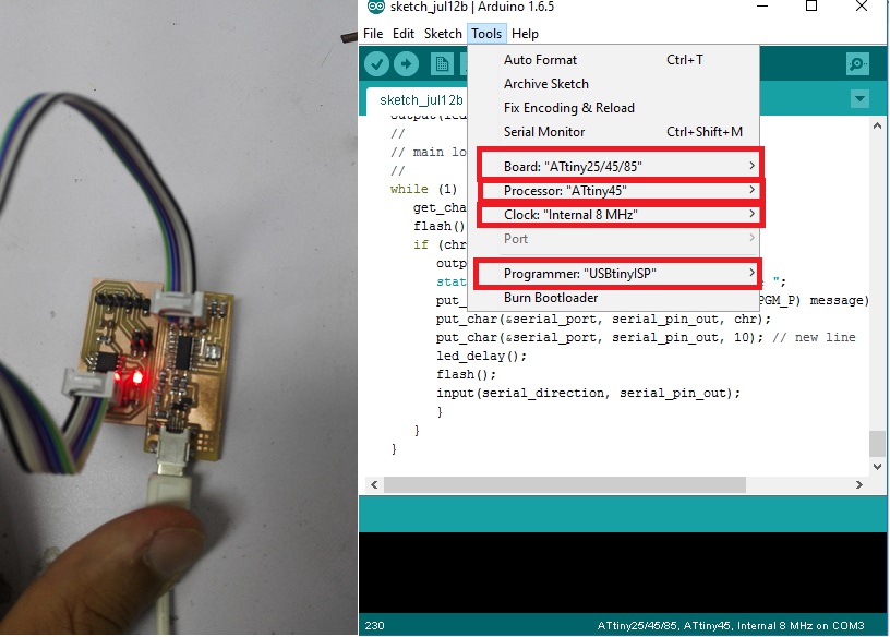
In the first trial I used Neil's Code
and I uploaded the code to the boards using the fab ISP using Arduino IDE as shown in the picture.
Video
in this video you will see the 3 boards are working that when I press '0' the first board (the bridge) flashes twice and the others flash only once
the others do the same when their id is called
The next Step (editing the code)
Neil's code was modified to make the node toggle the LED everytime you call it. So if you send to node 0, it will turn the led on then if you send to it again it will turn the LED off. the flashing part was kept to detect serial communication on the bus.
The macro toggles pin between 1 and 0 everytime it's called. So using logical XOR on the PORT pin and 1. If the PORT pin is 1, it will be 0 (1 XOR 1 = 0) and if the PORT pin is 0, it will be 1.
#define toggle() (led_port ^= led_pin)
The flash function is changed to use toggle macro instead of writing to the pin high or low.
void flash() {
   // flash the led
   toggle();
   led_delay();
   toggle();
}
and the main loop is still as previous.
but i just added toggle();
in the end of the main loop.
in the next video you will find the bus making the toggle function.
The final code
Conclusion
by the same way you can connect many microcontrollers (each one has its on address) together and make them communicate easily and they may be distant and communicate by bluetooth or wi-fi and do different functions which enables us of more great ideas.