13th Assignment
Output Devices
This assignment is about Adding an output device to a microcontroller board you've designed and program it to do something
Stepper Driver
In this assignment I've decided that I need a stepper driver to my SmartCurtain as it will be driven by a stepper motor.
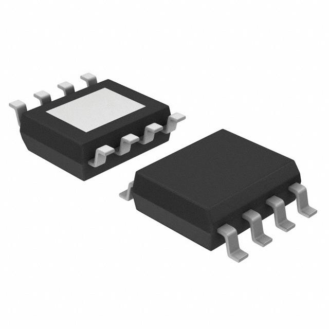
I used two a4953 stepper drivers
you can download the datasheet from HERE.
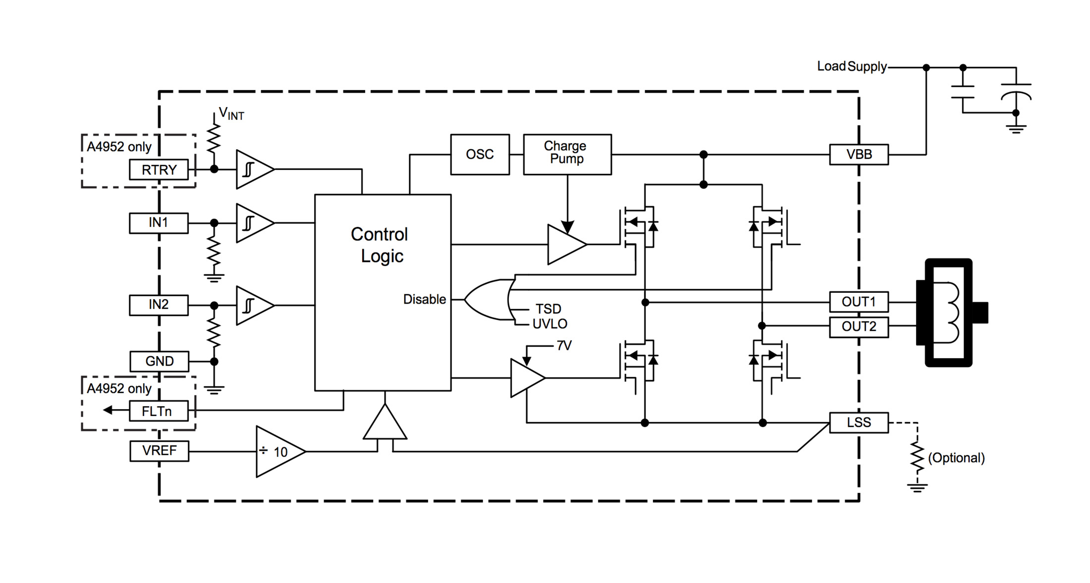
functional block diagram
Regarding the motor driver,The A4953 overcurrent protection can only be reset by putting the
device into standby mode or by cycling the power to VBB. In order to use PWM current control –page 1 of the A4953 Datasheet– a low-value resistor can be
placed between the LSS pin and ground for current sensing purposes.
but I don't think that my application in that need of this resistance as it's not heavy load or continuous work.
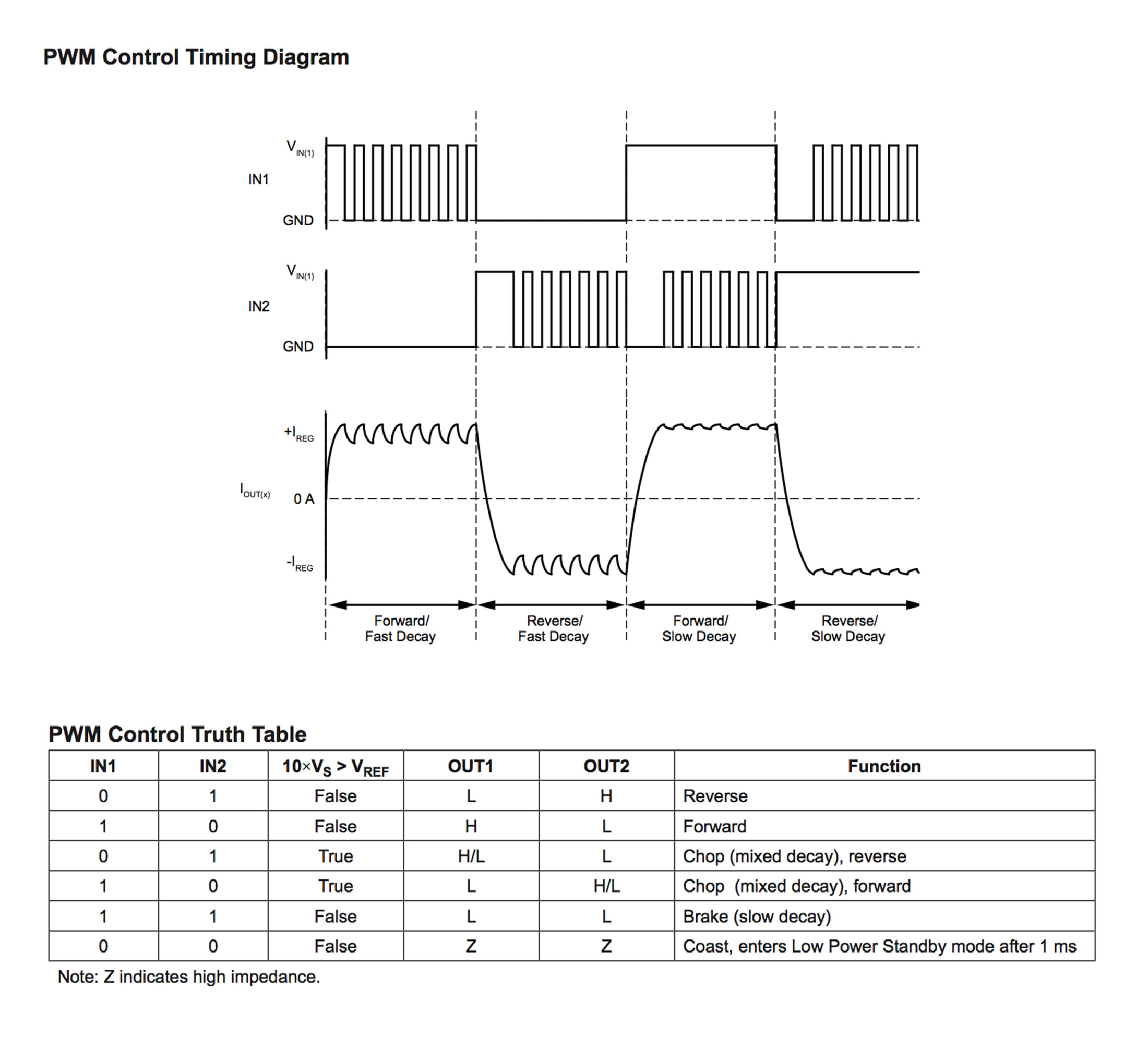
control timing table
from page 4 of the data sheet I've found the orders needed to get such movements.
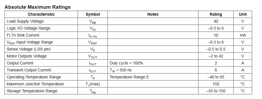
Knowing the driver's extremes
I also made sure about the maximum ratings of the driver from this table.
Used Libraries
I used Eagle to design the PCB.
the used libraries in this PCB were:-
fab.lbr
ng.lbr
I also used another library for the pin headers of the FTDI because In the lab we are using
another package than the regular one used in FAB library.
EAGLE-BOARD-TO-BOARD_CONNECTORS-rev16c.lbr when adding these pins from the library search for "61000618221".
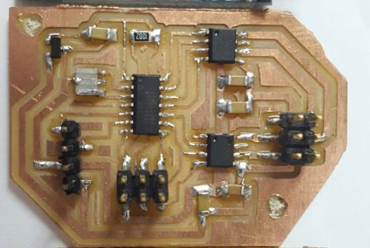
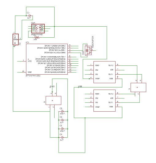
Stepper driver PCB's Schematic
I worked in designing this PCB the same way I made the design in Electronics Design Assignment
At first I designed the schematic of the hello.stepper.bipolar.44 by adding the components in the schematic view and connecting them.
I also connected a 20 MHz Resinator to make it possible to me to code it using Arduino.C and use SoftwareSerial.h.
I've Also connected two pins for TX and RX.
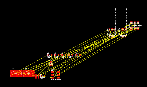
Switching to board layout
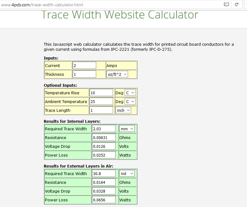
Calculating the high current traces width
I've used This website to determine trace width of the lines that takes the current of the stepper motor not to be a large resistance.
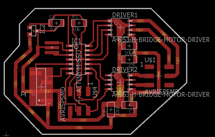
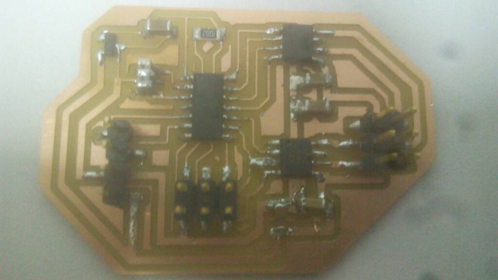
after arranging the components and make the taces
this is how it looked after making the traces.
Changing the FTDI headers
then I changed the FTDI headers to the available type in the lab.
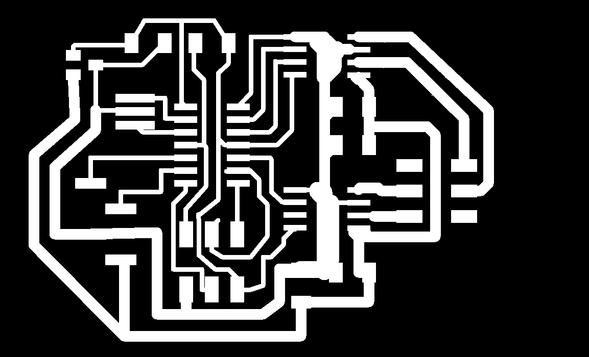
Exporting
Then I needed to export both the traces and the outline, here it's how it looked after exporting as monochrome and with 500 dpi and after editing the outline
as explained in the electronics design assignment.
Note that I've made little edit to make two holes for fixtures.
Downloadable links for the traces and the outline.
Traces.png
Outline.png
Downloadable Eagle Files
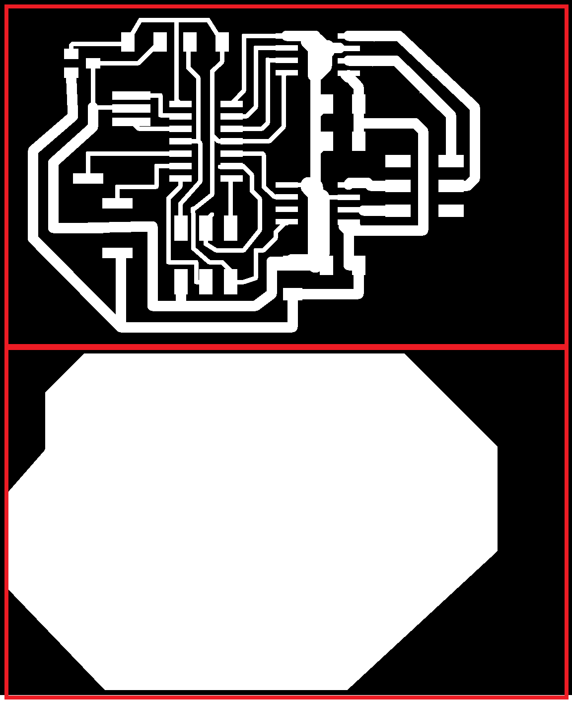
PCB before the edit
PCB after the edit
The Coding Phase
I used Niels Code with some edits in namig the ports because it was confusing to name the ports A1 and A2 as these names are the names of the pins on the ATTiny 44,
and uploaded it using Arduino as this tutorial explains.
It can be uploaded using FabISP like the last step in embedded programming assignment.
In the edited code I described briefly the code lines and what it did.
if you want to know more details you You can check the embedded programming assignment to see:-
how I configured the pins (Input & Output pins).
and how I set the clock divider to be /1.
and which registers are responsible of tuning the internal oscillator if you want to tune it,
but I am not in need of this because I am using an external oscillator.
In the following steps I will explain the remaining of the lines of the code which weren't explained in details in the embedded programming or the comments in the code.
Working principle of Stepper Motor
I've found a really useful link that helps in knowing how it works.
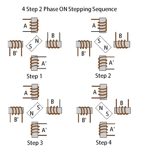
The full step sequence or the 2 phase ON sequence,
is when two adjacent phase windings are excited at a time so that the rotor is positioned at a point resultant to both the fields.
the stepping sequence diagram is shown in the picture.
Each one of the coils is connected to a driver which means that coil A is connected to PA0 and PA1, and coil B is connected to PA3 and PA4.
these code line are the responsible for making one pulse of the pulses which makes the positions explained in the picture.
          // A+ B+ PWM pulse
//
void pulse_ApBp() {
  clear(bridge_port, Ab); //disables Ab
  clear(bridge_port, Bb); //disables Bb
  set(bridge_port, Aa);   //enables Aa
  set(bridge_port, Ba);   //enables Ba
   for (count = 0; count < PWM_count; ++count) {
      set(bridge_port, Aa); //enables Aa
      set(bridge_port, Ba); //enables Ba
      on_delay(); //PWM on time (Previously defined)
      clear(bridge_port, Aa); //disables Aa in the end of the pulse
      clear(bridge_port, Ba); //disables Ba in the end of the pulse
      off_delay();//PWM off time (previously defined)
      }
   }
These lines are making cycle of positions which makes one cycle by the stepper motor in clockwise or anti-clock wise direction.
// clockwise step
// by this sequence of pulses we will get a step in clockwise direction
void step_cw() {
   pulse_ApBp();
   pulse_AmBp();
   pulse_AmBm();
   pulse_ApBm();
   }
//
// counter-clockwise step
// by this sequence of pulses we will get a step in anti clockwise direction
void step_ccw() {
   pulse_ApBm();
   pulse_AmBm();
   pulse_AmBp();
   pulse_ApBp();
   }
It's working!
Another code working with TX&RX
Download The Used Code
You can check how I connected it via bluetooth from HERE