_Week10_OUTPUT DEVICES
_Introduction
Output devices week brings us the possibility of creating our own board to be able to control our own output device being able to be controlled by us through the programming without needing to be controlled with another type of commercial board, in addition to the ability to engage more into the possibilities offered by a microcontroller for the development of a specific project with the desired output device.
_Background
An output device is any peripheral that receives data from a computer, usually for display, projection, or physical reproduction, these ones could be sound, video, movement, light for example; gathering a bunch of components to make an specific action programmed.
_Week Assignments
_Workflow /Step by Step
_Choose Output device.
For this week assignment, I wanted to work with the microservos in order to improve the performance of Mr.Rob-berto so I started to look about the datesheets of the differents types of servos and its specifications, how to control it and (why not) improve the Hello.Servo from 2 to 4 microservos (which is the number of axes of Mr.Rob-berto).
Interest links
- Datasheet from the microservos that I got.
- Servo Cookbook.
- A commercial board that drives many servos.
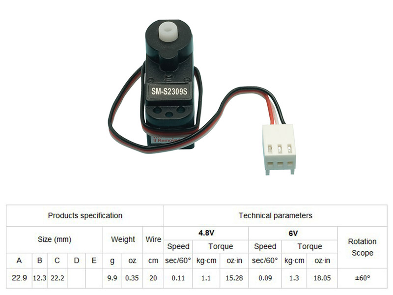
After the read, in order to improve the hello.servo.44, I got to pay attention in the Voltaje and the current which they work to keep the movement smooth and all works correctly (better performance at 6V stable); and also their communication (PWM pin) with the microcontroller that i'll choose and the pinout of this one (VCC is red, GROUND is brown and SIGNAL is white).
_Choose microcontroller.
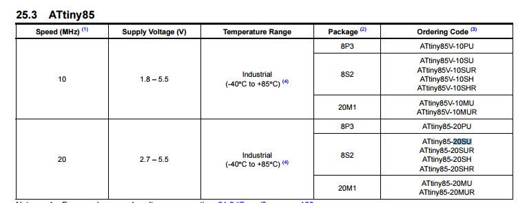
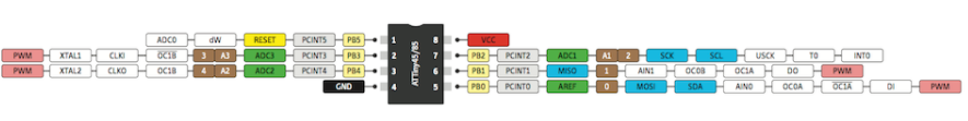
As a result, I choosed the ATtiny85 for the following reasons (that for the first time after read the datasheet I finally understand more about it):
- It's a powerful, tiny and cheap microcontroller easy to work with it and to take advantage of your specifications
- The ATtiny85 have more memory flash than the ATtiny44 , this is in order of the weight to run the code to control the 4 microservos.
- Just for changing the same microcontroller and having more fun finding how to make it work as I want it.

But during this work I will have different obstacles to solve like these:
- Change the voltaje regulator for the 1 AMP that i found in the FabInventory to have good performance of the microservos.
- Found two 8-bit counter library compatible with ATtiny85 servo8bit.h and SoftwareServo.h for control microservos since these work normally at 16-bit counter servo.h library.
- Also a past Yue Siew Chin FabAcademy student worked with the ATtiny85 for control 2 microservos but this was a very good point to start my work.
- As well, in order to having two more PINS to connect the other two microservos I skiped the external resonator and use the internal: one way is to tuning the ATtiny internal occillator and the other one is in the moment of burn bootloader attiny85 internal clock.
- Using MOSI and MISO pins for having the other two pins to connect the servo 3 and 4 because actually this pins are only need when programming the board.
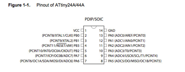
In short, using the ATtiny85 pines 2,3,5 and 6 for connecting the microcontroller to have communication with the servos.
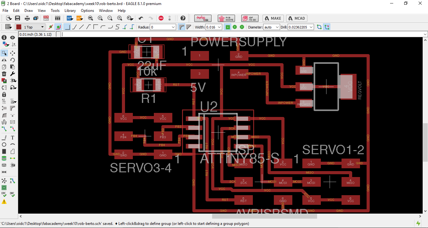
_Board design and mill.
After knowing the advantages and the limitations of the microcontroller, I started to design the board in function of having all the pins occupied:
- PIN 1 : 10K resistor
- PIN 2 : Signal servo1 (skipping the CLK1 to the external resonator).
- PIN 3 : Signal servo2 (skipping the CLK0 to the external resonator).
- PIN 4 : GND
- PIN 5 : VCC
- PIN 6 : SCK
- PIN 7 : MISO/Signal servo3
- PIN 8 : MOSI/Signal servo4
Here is the list of components that I used:
- (1) ATtiny85.
- (1) 10K resistor
- (1) 22uF Capacitor
- (1) 1 AMP Voltaje regulator
- (1) 2x2 header.
- (3) 2x3 header.
As well, I need to download all the ATtiny Eagle library for using it in the schematics for the design of the board.


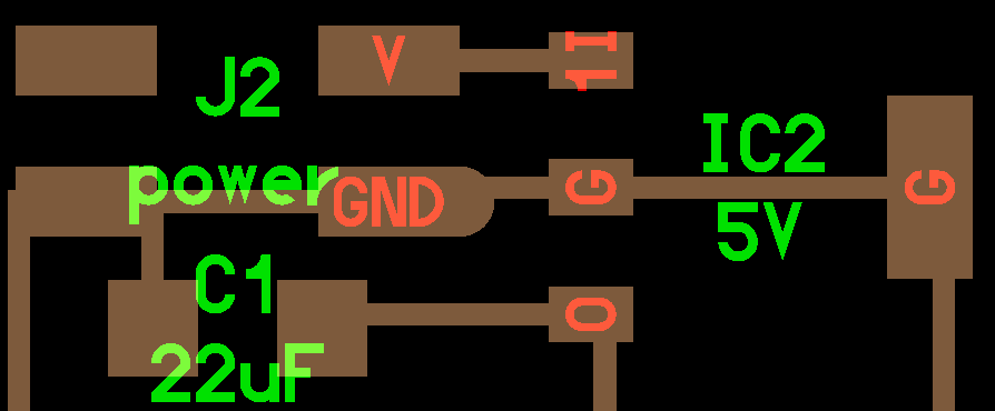
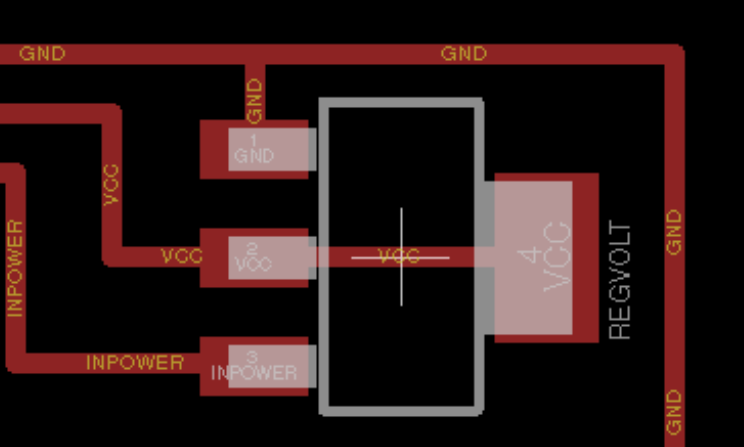
NOTE: As in the past years, the schematic from Neil have a past model of Voltaje regulator that have change the orden of the pins for being installed as the new Voltaje Regulator .The first picture show the past orden of the pins (the middle are GROUND) and the second one show the actual orden (the VCC pin in the middle).
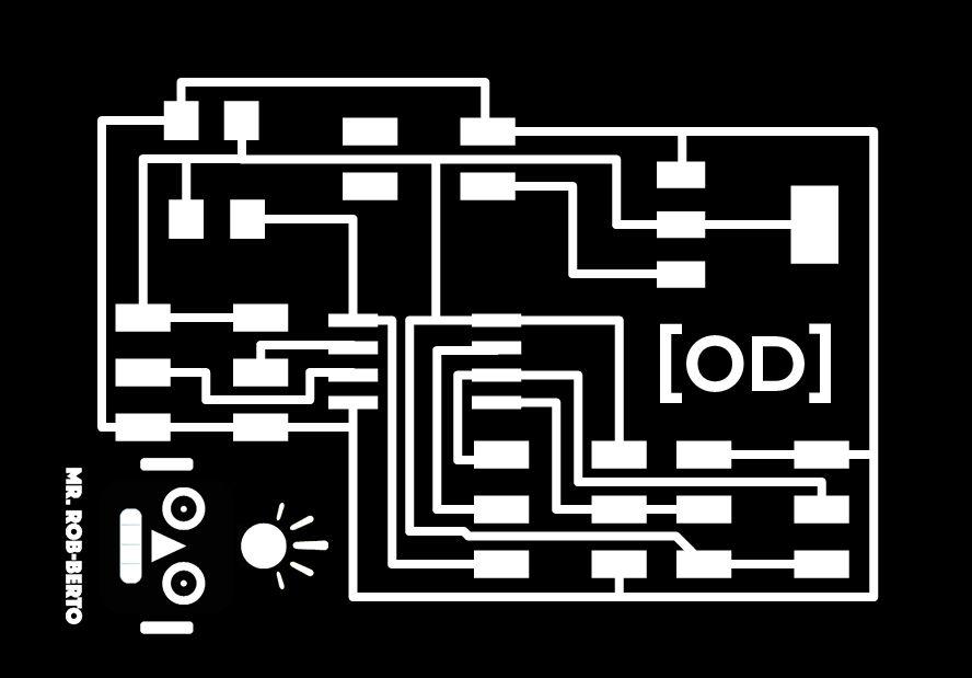
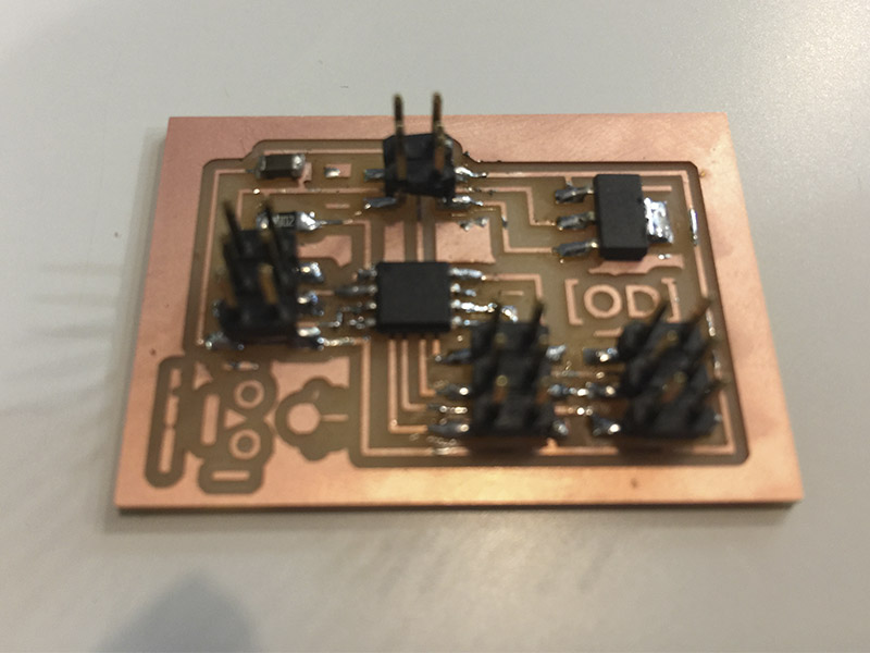
Therefore, this how the board looks like after milling and soldering(im getting better in this).

_Programming process.
So HERE COMES THE PROBLEMS... well I think so after all these days I'm getting better in some skills that I never imagine and programming is one. At first I've connected the board the AVR turn green (thanks God) and now it was ready to be programmed.

For the first time I've try to programm my board with my own computer (avoiding the warning of probably erase some paths in your system) because always appeared and error during the "Burn bootloader" and i've been doing it in other friends computers. Therefore, following the advice of my friendJulia Leirado that had the same problem with Windows, I did the next steps to finally programm my board with the FabTinyISP and make it work with the 4 microservos:
- Download and install USBtiny drivers to the computer in order to recognize the FabTinyISP.
- Open the Arduino IDE and do the same steps as the week08 for program for the first time the board. NOTE: in this step instead of program with the External Clock 20Mhz as usual I put Internal Clock 8Mhz in order of using the internal ocillator of the microcontroller.
- Download and install SoftwareServo.h that is the servo 8-bit counter library in the Arduino Files for using it for the code.
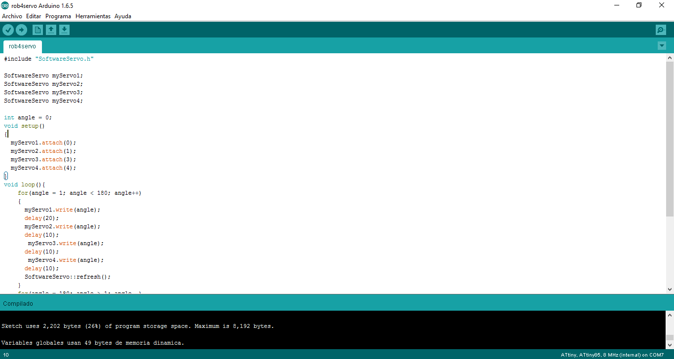
- The code is here:
#include "SoftwareServo.h" SoftwareServo myServo1; SoftwareServo myServo2; SoftwareServo myServo3; SoftwareServo myServo4; int angle = 0; void setup() { myServo1.attach(0); myServo2.attach(1); myServo3.attach(3); myServo4.attach(4); } void loop(){ for(angle = 1; angle < 180; angle++) { myServo1.write(angle); delay(20); myServo2.write(angle); delay(10); myServo3.write(angle); delay(10); myServo4.write(angle); delay(10); SoftwareServo::refresh(); } for(angle = 180; angle > 1; angle--) { myServo1.write(angle); delay(20); myServo2.write(angle); delay(10); myServo3.write(angle); delay(10); myServo4.write(angle); delay(10); SoftwareServo::refresh(); } } - By now I could not programm it on my computer because I have a problem with an update of Windows that start to fail my USB ports and doesnt recognize the FabISP. Therefore, I was able to programm it with the great help Xavi Dominguez and his computer AND FINALLY I COULD HACK THE ATTINY85 WITH 4 SERVOS!!!!
_FILES
All the files for this assignment are available to download here