Embedded Networking & communication
Task to do-
To design and build a wired &/or wireless network connecting at
To design and build a wired &/or wireless network connecting at
What I have done-
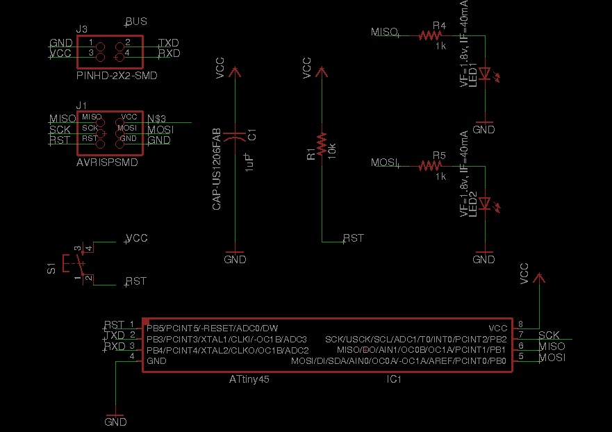
In this assignment I used 1 Bridge and 2 nodes.I have downloaded bridge from fab academy class archive and edited node by adding one led and button. used arduino IDE for downloading the program on boards Before that I understood what mean by networking If we take day to day example then Networking is simply an information exchange between you and another person. It involves establishing relationships with people. A network consists of two or more computers that are linked in order to share resources (such as printers and CDs), exchange files, or allow electronic communications. The computers on a network may be linked through cables, telephone lines, radio waves, satellites, or infrared light beams. Here in our case we are using 2 processors which are communicating each other.For understanding of how to do this I referred ready board for networking.I am using 1 bridge and 2 node boards. first I have edited node boards in eagle.For adding button on it.
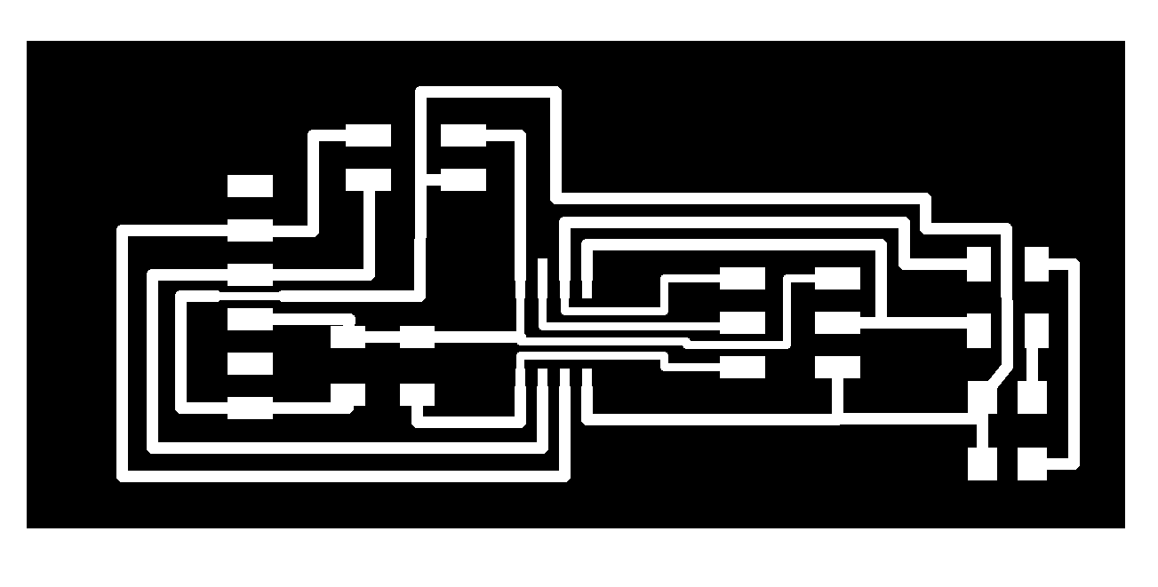
Layout of bridge
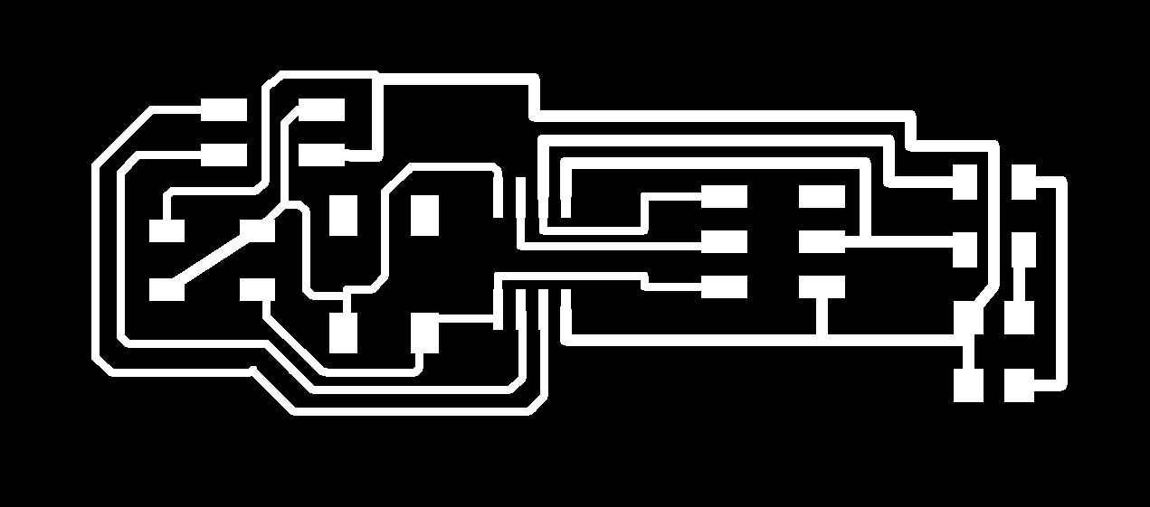
Layout of Node
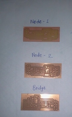
After edition I milled these on Modella machine. Soldered as per given components and circuit diagram

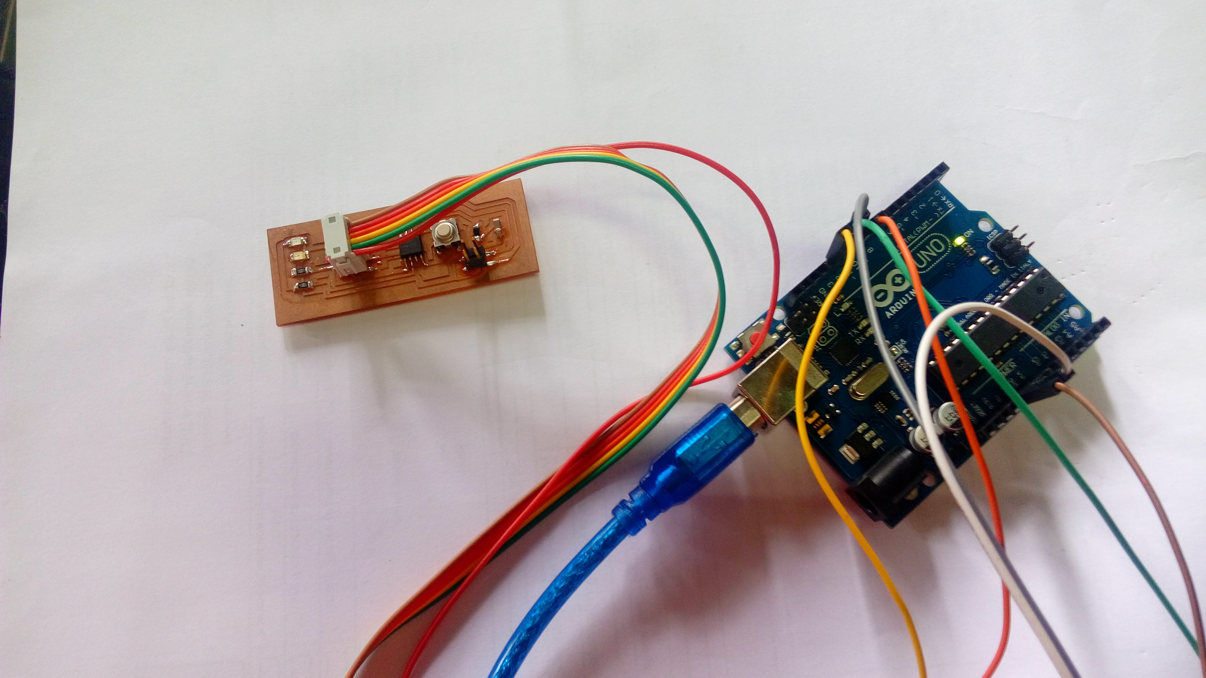
I used Arduino to program Each node and Bridge.At the time of programming I have put same code in 3 boards one by one.But you have to take care about one thing that is,when we are programming bridge we have to put '0' in node id place as shown in below image.

Simillerly for node1 put '1',For node2 put '2',But NOTE that we have to arrenge these boards in same way as Bridge at 0 position,node1 at 1st and node2 at 2nd psition.It means we are going to connect FTDI cable to coputer then bridge to FTDI, After bridge node1 and then node2.
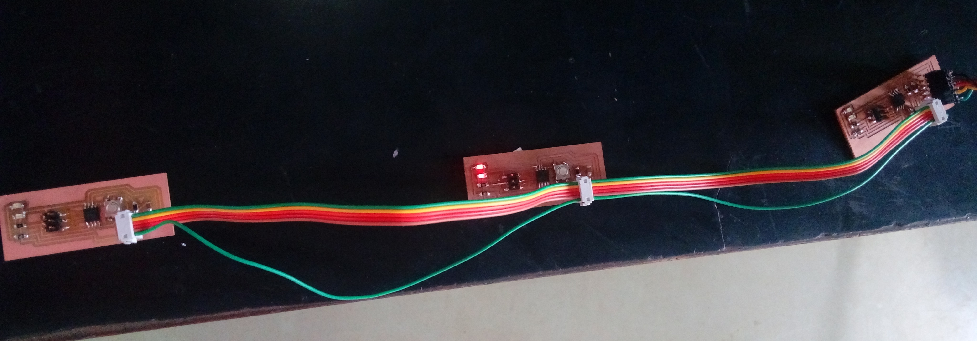
Connections and working:
Here I am doing communication through serial monitor with bridge and node boards. So
for that I connected bridge board to computer through FTDI cable. Connected between bridge and
node boards are with simple male-female connector.
for that I connected bridge board to computer through FTDI cable. Connected between bridge and
node boards are with simple male-female connector.
It works like when we write 1 in serial monitor of arduino IDE that will give signal to node one and other 2 boards ,that is Bridge and node 2 will be off
and LED of node1 will blink. Same case happens with node 2; if we write 2 in serial monitor led on node2 will blink and other 2 boards will remain off.If you write 0
in serial monitor then bridge LED blinks and LED on other 2 boards stops.
NOTE-At the time of programming we are going to connect 6 pins on bridge or node to arduino or any programmer which we are going to use.But after finishing with programming when we are going to execute this code we have to connect boards by using 4 pins (receiver,transmitter,vcc,gnd).I had made this mistake at the time of exicution of programme.
I have linked edited boards and programme below.Actually in this assignment I learned to make network between self made board.It was very new experience for me.I learnt to make communication between micro controllers and importance of receiver and transmitter of microcontroller.