WEEK 11 - input devices
TASK:
Objectives:
- Decide on which sensor to work on.
- Design board using Eagle.
- Milling & stuffing board.
- Programme board using arduino as ISP
- Test board
Decide on which sensor to work on
1) Phototransistor
To follow on with the persual of the final project, phototransistor sensor was selected as sensing device.
Phototransistors are essentially light-sensitive transistors that convert light energy into electric energy.
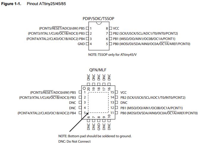
2) This week, the sensor board was designed using a ATtiny 45 chip.
As compared to ATtiny 44/44a, 45 has:
- lesser pins (6 instead of 12)
- SPI (1 instead of none)
- 8-bit counters (2 instead of 1)
- 16-bit counters (none instead of 1)
- ADC (4 Ch instead of 8)
Following are the pin configurations of an ATtiny45:
Design board using Eagle
Software Downloads: Eagle
Reference: Sally Williams (class of 2015)
Download Eagle files: Schematics file Board file
Before heading straight to designing the phototransistor board, the following were considered:
- Add an LED to allow visual reponse when phototransistor receives signal (see above reference).
- FabISP done in week 4 was not working due to cold joints, arduino will be deployed instead.
Here are some of the critical steps:
a) To begin with, here are the list of components prepared:
- ATtiny 45
- Resistor 10K
- Resistor 1K
- Resistor 499
- Capacitor 1 uF
- HDR 2x3
- FDTI HDR
- LED Red
- SM/Phototransistor: NPN 1206
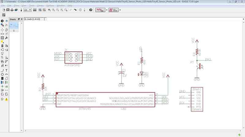
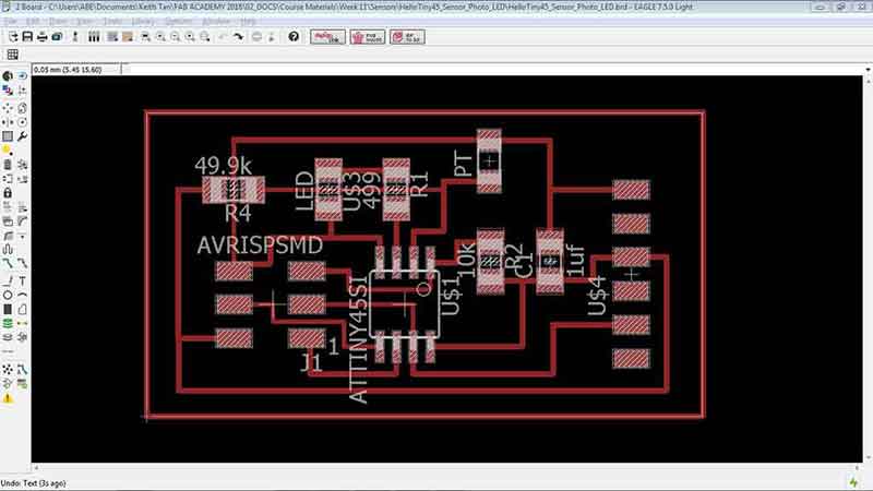
b) Next, a schematics design of the board was set up in Ealges. Since an LED was added to the design, an extra resistor was inserted to the board as compared to the Fabacademy phototransistor design example.
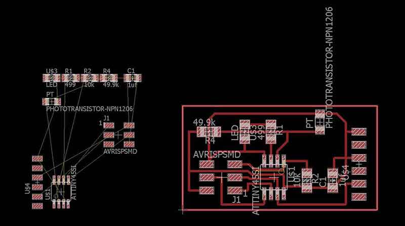
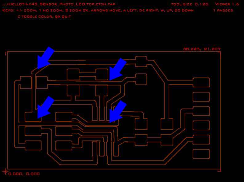
c) Following that, the board design was generated and arranged. Part of the struggle while arranging the board design was the limited routing space in-between the ATtiny 45. The initial design (as shown below) was very cluttered and according to our instructor, the chamfered route corners are prone to milling errors. Sure enough, once the design was exported to the CNC miller software, the routing widths were too large and some encroached into other routes.
Interestingly, due to the (very very long) naming of the Phototransistor component (as seen below), the CNC milling software dectected it as an extention to the board and replicated a second empty board. This was later resolved by simply removing or renaming the title by clicking onto the component and check the box that says "overwrites device name".
d) The routes for the board design was re-adjusted and send for milling.
Milling & Stuffing board
1) Milling
Refer to milling process here: week 6
Gcode for ATtiny 45 Sensor and LED board: Download
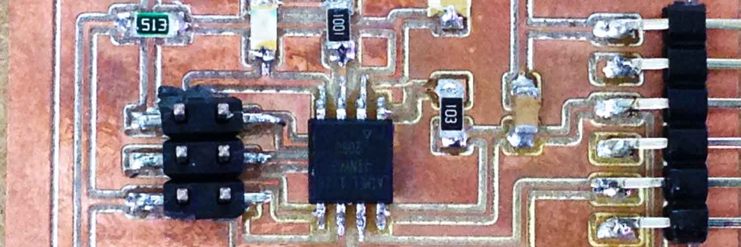
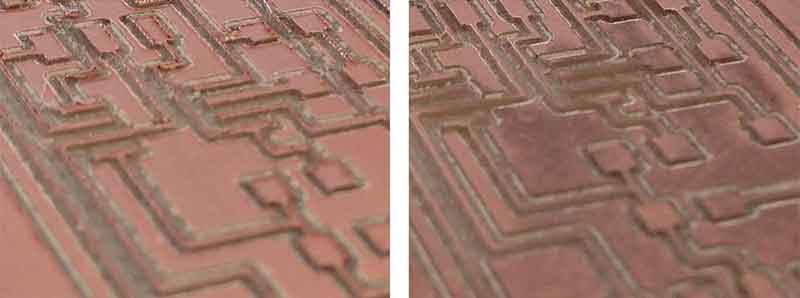
The milling process went smoothly except for the first attempt. The board was milled a little too deep and some of the copper were chipped off and removed.
This was also partly due routing the traces too near to each other. As shown below, the left image of the first milling attempt had copper parts removed whereas
the board on the right had all copper intact. Although the second attempt had all the copper intact, the milled depth was still rather deep. This might cause weaker
connectivity due to insufficient copper along the traces. Due to time contraint, stuffing was proceeded using the second board. The board was sanded with sand paper
(range 200) and washed with soap.
Programme board using arduino as ISP
To program the ATtiny 45 Phototransistor and LED board, do the following:
- Make sure arduino has been uploaded with Arduino ISP
- Connect arduino with ATtiny 45 sensor board
- upload the "switch" example from arduino IDE to the ATtiny 45 sensor board
1) Make sure arduino has been uploaded with Arduino ISP
Refer to week 8 on example of how to setup arduino and uploading Arduino ISP.
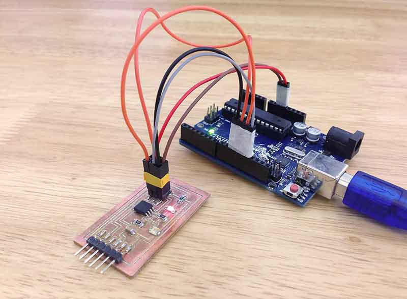
2) Connect arduino with ATtiny 45 sensor board
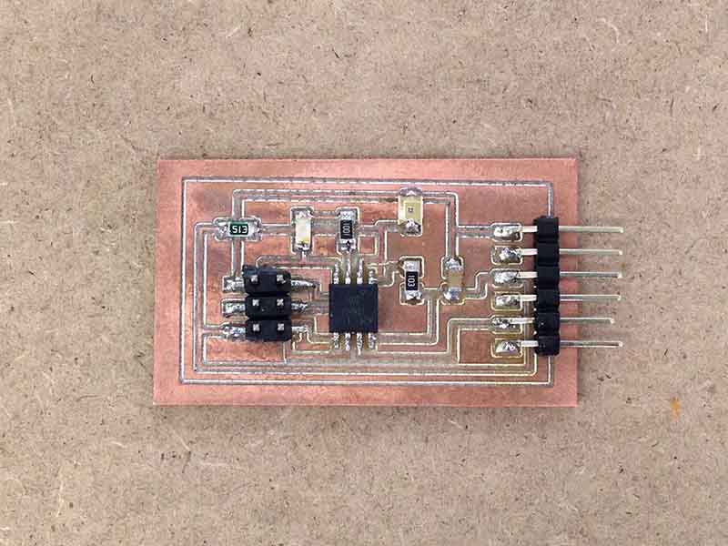
This happened to be one of the more crucial learning for this week. The boards were accidentally mis-wired and also a couple of cold joints on the board, it took about a day to figure out the cause and to move on with testing the program. Nevertheless, below are some notes to take care of the confusion:
- Ensure that all components are named in the board interface (Eagle)
- Alternatively, click on each connections to find out the signal name such as GND, VCC etc.
- ATtiny 45, Phototransistor and LED are polarity sensitive. Positive signal is denoted by the green ink on the components. Ensure that the positive end faces the resistors instead of the ground signal (GND). For ATtiny 45, ensure that the "dot" (loacted on the chip itself) faces and connects to the 10K resistor.
Using the "Button" example, change the LED pin numbers as required. This creates an LED on/off effect when phototransistor is either covered or uncovered, simulating lights on and off. To reverse the LED reaction, simply change the LED state from High to Low or vise versa.
  // set pin numbers:
const int buttonPin = 3;     // the number of the pushbutton pin
const int ledPin =  4;      // the number of the LED pin

// variables will change:
int buttonState = 0;         // variable for reading the pushbutton status

void setup() {
  // initialize the LED pin as an output:
  pinMode(ledPin, OUTPUT);
  // initialize the pushbutton pin as an input:
  pinMode(buttonPin, INPUT);
}

void loop() {
  // read the state of the pushbutton value:
  buttonState = digitalRead(buttonPin);

  // check if the pushbutton is pressed.
  // if it is, the buttonState is HIGH:
  if (buttonState == HIGH) {
    // turn LED on:
    digitalWrite(ledPin, HIGH);
  } else {
    // turn LED off:
    digitalWrite(ledPin, LOW);
  }
}
Reflections
The assignment for this week has been something that most of us have been anticipating for and mostly for 2 reasons. Firstly, by mastering (or perhaps more like tinkering) the sensors and knowing how they work, the realization of the final project would be drawing closer. Secondly, this also meant that the Fab Academy course has crossed it's halfway mark. Kudos to the team members that have been working very hard on their projects. This definitely kept our hopes and spirit high!
To further develop the phototransistor exercise, the codes can be altered to allow LED to fade in and out depending on intensity of the light source. Also, as an add-on to the final project, a moisture sensor can be added to detect rain. This way, the final project can be geared towards sensors moving louvres or parts of a building. This will be further developed in weeks to come.
All-in-all, this week has been a fantastic week and we are looking forward to expanding ideas!
Download Eagle files: Schematics file Board file
Gcode for ATtiny 45 Sensor and LED board: Download

Related Projects