WEEK 8 - Embedded Programming

TASK:
* read a microcontroller data sheet.
* program your board to do something, with as many different programming languages and programming environments as possible.
* Read data sheet to discover interesting facts.
* Use Arduino as AVR ISP to install Bootloader onto Echo Hello ATtiny 44 board.
* Program Echo Hello ATtiny 44 board with different scenarios.
* Connect Echo Hello ATtiny 44 board to communicate with FTDI USB to TTL Serial Converter.
* Install and use AVRdude to send MakeFile to Hello ATtiny 44 through FAB ISP board to communicate.
Read data sheet to discover interesting facts
1) What is the difference between ATtiny 44 and ATtiny 44A?
ATtiny 44 was introduced in Dec 2005 to optimize manufacturing process and reduce current consumption. ATtiny 44A was introduced in Dec 2008 and is identical in functionality but differ in electrical characteristics. They were produced with seperate datasheets. Details can be found here: http://www.atmel.com/Images/doc8187.pdf.
2) What are the characteristics of an ATtiny44A?
a) There are 14 pins on this chip
b) VCC supplies voltage
c) GND is ground
c) Port B (PB3:PB0) is a 4-bit bi-directional I/O port with internal pull-up resistors
d) RESET (PB3) A low level on this pin for longer than the minimum pulse length will generate a reset
e) Port A (PA7:PA0) is a 8-bit bi-directional I/O port with internal pull-up resistors
f) Port A has alternate functions as analog inputs for the ADC, analog comparator, timer/counter, SPI and pin change interrupt
g) CPU(central processing unit) ensures correct program execution by accessing memories, performing calculations, controlling peripherals, and handling interrupts
h) There are three types of memory
Flash stores the compiled program even when the power is off
i) SRAM saves temporarily variables while calculating
j) EEPROM is for data storage
k) ATtiny44A features successive approximation Analog-to-Digital Converter (ADC). It generates a 10-bit result which is presented in the ADC Data Registers, ADCH and ADCL. ADCL presents only the low byte of the ADC conversion result and ADCH presents only the high byte. ADCL is read first, then ADCH. When ADCH is read, ADC access to the ADCH and ADCL Registers is re-enabled and a new result is provided.
3) What is a Watchdog Oscillator (found under item 6: Clock System in data sheet)?
It is a safety feature and an electronic timer designed to detect and recover malfunctions. Check out this blog for more details.
4) How do we specify Clock Sources?
Under 6.2 (Clock Sources) of the datasheet, Flash Fuse bits are selectable according to clock source represented in the table (table 6-1) shown. These clocking sources determine the stability of oscillation operations (timing or delays) before instruction execution begins, be it when the CPU wakes up or when starting from a reset.
Use Arduino as AVR ISP to install Bootloader onto Echo Hello ATtiny 44 board
Software Downloads: Arduino IDE Arduino ISP Older Arduino ISP Releases
Reference: http://highlowtech.org
Download ArduinoISP file: ArduinoISP.ino
Map of working process:
Install Arduino IDE> Install Arduino ISP> Connect Computer to Arduino> Upload Arduino ISP Sketch onto Arduino> Connect Arduino to Hello Board> Burn Bootloader onto Hello Board.
Here are some of the critical steps:
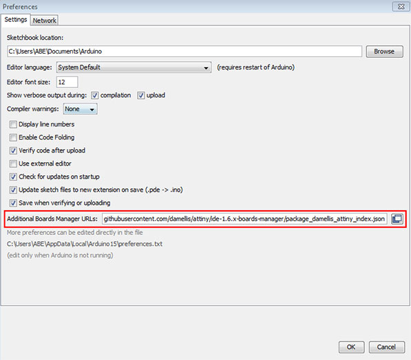
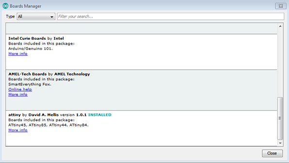
a) Installation of IDE and Arduino ISP can be found at http://highlowtech.org. The key is to download the driver through the "Additional Boards Manager URLs" field under File> Preferences. Then, install Arduino ISP via the in-built boards manager. Go to menu> tools> Board> Boards Manager. Ensure that the "Compilation" and "upload" checkboxes are selected.
b) Connect Computer to Arduino via a USB cable.
c) Upload Arduino ISP Sketch onto Arduino. Observe the following steps:
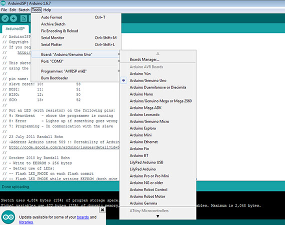
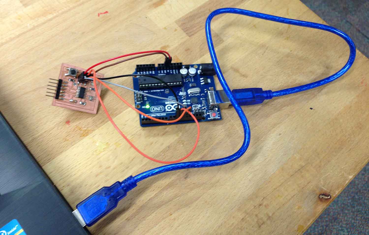
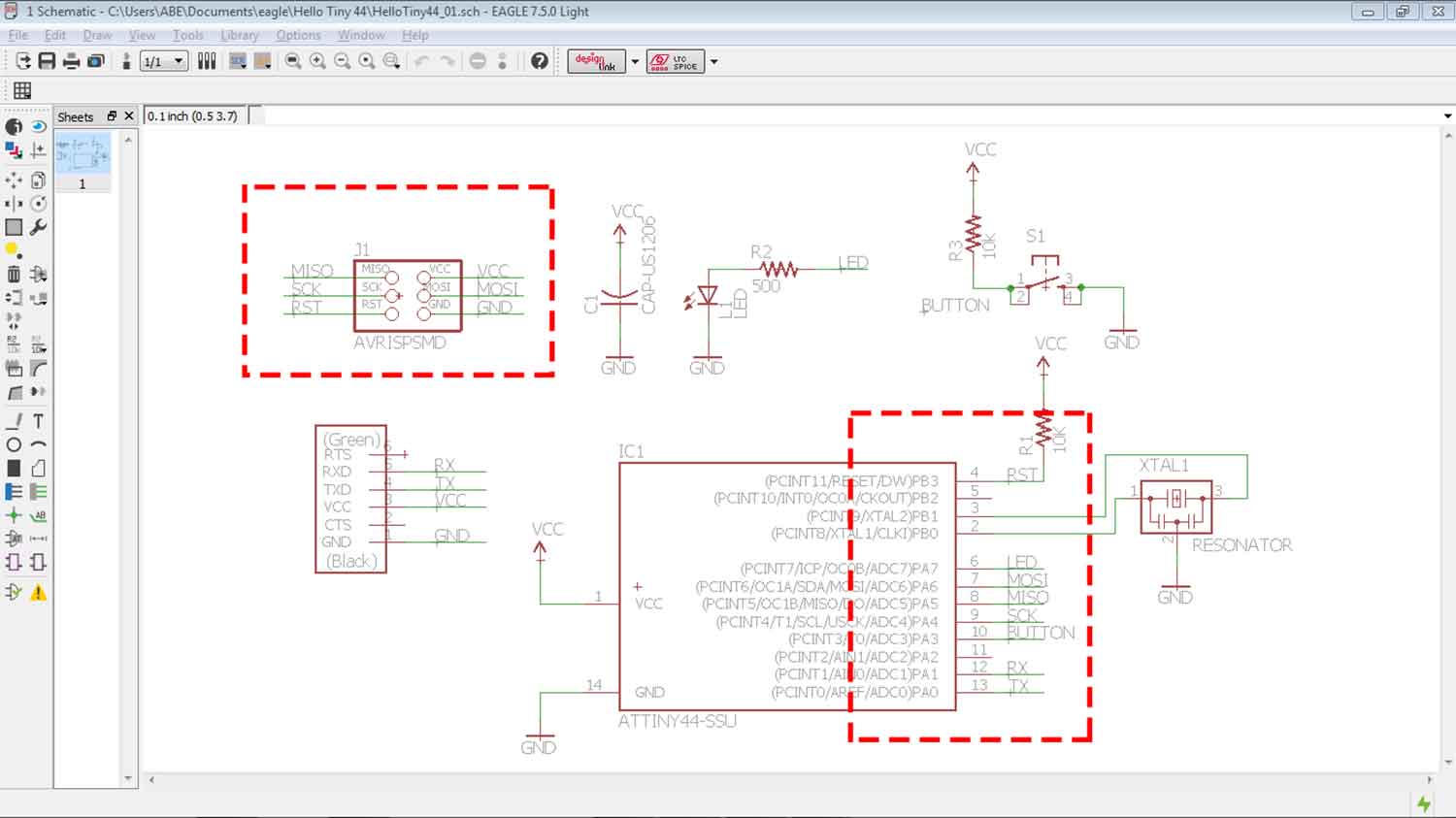
d) Connect Arduino to Hello Board. This was done with reference to the schemetics done in Eagles and the ArduinoISP Pin locations.

f) Burn Bootloader onto Hello Board. Go to Tools> Burn Bootloader. Upon successful uploading, data in Arduino IDE should end with something similar to the following:
avrdude: Device signature = 0x1e9207
avrdude: Send: Q [51]   [20]
avrdude: Recv: . [14]
avrdude: Recv: . [10]

avrdude done.  Thank you.
Download generated C Program codes: 03_Bootloader data for Attiny 44
Program Echo Hello ATtiny 44 board with different scenarios
To program the Echo Hello ATtiny 44 board, open up the "Blink" sketch example in Arduino IDE and upload it. Once uploaded, the Hello should work according to the sketch. Here are some that has been tested.
Using the "Blink" example, change the LED pin numbers as required. This creates a slow blinking LED.
  digitalWrite(7, HIGH);   // turn the LED on (HIGH is the voltage level)
  delay(1000);              // wait for a second
  digitalWrite(7, LOW);    // turn the LED off by making the voltage LOW
  delay(1000);              // wait for a second
Amend the sketch again to create a fast blinking LED.
  digitalWrite(7, HIGH);   // turn the LED on (HIGH is the voltage level)
  delay(100);              // wait for a second
  digitalWrite(7, LOW);    // turn the LED off by making the voltage LOW
  delay(100);              // wait for a second
Amend the "Button" sketch to light up LED when button is pressed.
Amend pin positons:
// set pin numbers:
const int buttonPin = 3;     // the number of the pushbutton pin
const int ledPin =  7;      // the number of the LED pin
Amend button states (swop the LOW and HIGH to change button state):
  // check if the pushbutton is pressed.
  // if it is, the buttonState is HIGH:
  if (buttonState == HIGH) {
    // turn LED on:
    digitalWrite(ledPin, LOW);
  } else {
    // turn LED off:
    digitalWrite(ledPin, HIGH);
  }
}
Connect Echo Hello ATtiny 44 board to communicate with FTDI USB to TTL Serial Converter
To allow the computer to communicate with the ATtiny 44 board, here's what needs to be done:
This sketch, adapted from the "Blink" example can send a message to PuTTy serial monitor when button is pressed and light up LED on the Hello ATtiny 44 board. It can also send a message to serial monitor and light up LED by pessing any key on the computer keyboard.
#include// constants won't change. They're used here to // set pin numbers: const int rx=1; const int tx=0; const int buttonPin = 3; // the number of the pushbutton pin const int ledPin = 7; // the number of the LED pin SoftwareSerial mySerial(rx,tx); // variables will change: int buttonState = 0; // variable for reading the pushbutton status int state; void setup() { mySerial.begin(9600); mySerial.flush(); // initialize the LED pin as an output: pinMode(ledPin, OUTPUT); // initialize the pushbutton pin as an input: pinMode(buttonPin, INPUT); } void loop() { while (mySerial.available() > 0){ state = mySerial.read(); } if (state == 'p') { digitalWrite(ledPin, HIGH); mySerial.print("Hello board says HELLO!!!"); delay(1000);} else { digitalWrite(ledPin, LOW); // read the state of the pushbutton value: buttonState = digitalRead(buttonPin); // check if the pushbutton is pressed. // if it is, the buttonState is HIGH: if (buttonState == HIGH) { // turn LED on: digitalWrite(ledPin, LOW); } if (buttonState == LOW) { // turn LED off: digitalWrite(ledPin, HIGH); mySerial.print("LED says YOU LIGHT UP MY WORLD!!!"); } } }
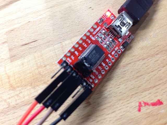
To Connect Hello Board to the FTDI USB to TTL Serial Converter, ensure that the pin connections are according to the Schemetics Design (Diagram shown below). Note: When connecting RXD (Returns) and TXD (Transmit), remember to flip the connections. RXD should connect to TXD and TXD connects to RXD.

Finally, open up PuTTY program, ensure that you select "Serial" under the Connection type menu and specify the Serial Line (USB Port) and Speed. Once done, click "Open" to test the communication simulation. Check out video below for documented process!

Install and use AVRdude to send MakeFile to Hello ATtiny 44 through FAB ISP board to communicate.
AVRdude Installer for Windows: Download
Makefile for ATtiny 44: Download
Tutorial: Click here
Map of working process:
Install WinAVR, follow Tutorial Here> Calculate and optain fuse configurations using Fuse Calculator> Connect computer to Hello ATtiny 44 board through FabISP board> Open up WinAVR using command prompt> Send!!
This part happens to be the most tedious portion of the entire exercise because it involves getting the boards ready, wiring them up, program and if things doesn't work out, it involves going back again to troubleshoot and to re-solder components if neccessary. The Hello ATtiny 44 board produced a few weeks ago worked out fine during the initial exercises but was completely unfunctional during last week. A second board was reproduced within a day this week and was able to carry out the first portion (as illustrated above) of the exercise exceptionally well. As soon as the connections were unplugged and re-connected for the AVRdude experimentation, errors were detected and troubleshooting did not revive the connections. The FabISP was able to be programmed again successfully but was unable to be detected in Macbook pro and HP laptop asked for drivers to be installed.

Although the attempts were without much fruit, here are some of the critical steps that were planned to be executed:
a) Install WinAVR. Once the program is installed, execution of commands will be via the command prompt. In windows click start and at the bottom click "cmd" to call up the command prompt. Type in "avrdude" to view the functionalities of the program.

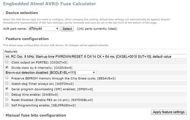
b) Next, go to Fuse Calculator to obtain fuse configuration for the hello board. Simply select ATtiny44 under the "AVR part name" section and click on the specifications under "Features" and make your selection.
c) Next, copy down the fuse configurations (arguments) for the next process.
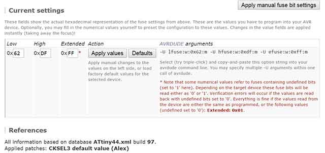
d) This would be where you need to specify configuration for fuse bits. You can either specify or set as default.

e) Finally, open up the command prompt and execute the command as follows.
>avrdude -c usbasp -p t44 -U lfuse:w:0x62:m0xff:m -U hfuse:w:0xdf:m0xff:m [PRESS ENTER TO EXECUTE COMMANAD]
Reflections
This week seemed to be the longest, though we had an Easter break last week, all tired out and weary especially when the boards failed to work. Having said that, the experimentations have been thorough and a few environments and boards tested. Below are some of the items for reflection and possibly re-visits:
All-in-all, this week has been an eye-opener!


Related Projects