This assignment I decide to experiment with the strong material , and the work with the composites, Due the flexibility of the materials.
Milling Challenge
We have at fab lab two machines to milling, in the last assignment we have the first contact using 360 fusion and designing a splint for molding and casting I this occasion we used the Cam Processor of fusion, in this case we had to experiment with the software Condacam, for milling our models.
.
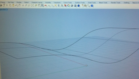
Testing Model in Rhino
We did a Simple model in rhino transforming the surfaces in a mesh > Export > STL data > Binary System
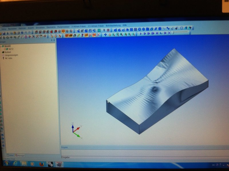
Conda Cam
Open the model pressing the option (model Laden)

Make model visible
Sometimes when you open the model you see only the lines going to Ansicht > Ausblenden > Model you can activate the view of your model.
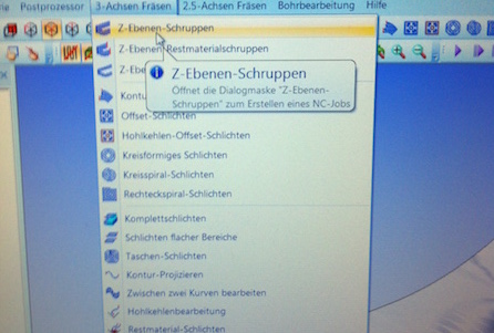
Rough Milling
Z ebenen Schuppen, you can give the settings for the first can begin from the black point that you localize in the top part of the model, you can see that the model is contain in a block in the block, which is your material. You have to place your model in the machine. If you set the 0 point in the top of part of the model you have to set the Z 0 of your machine in the top part of your material !! don't forget it!
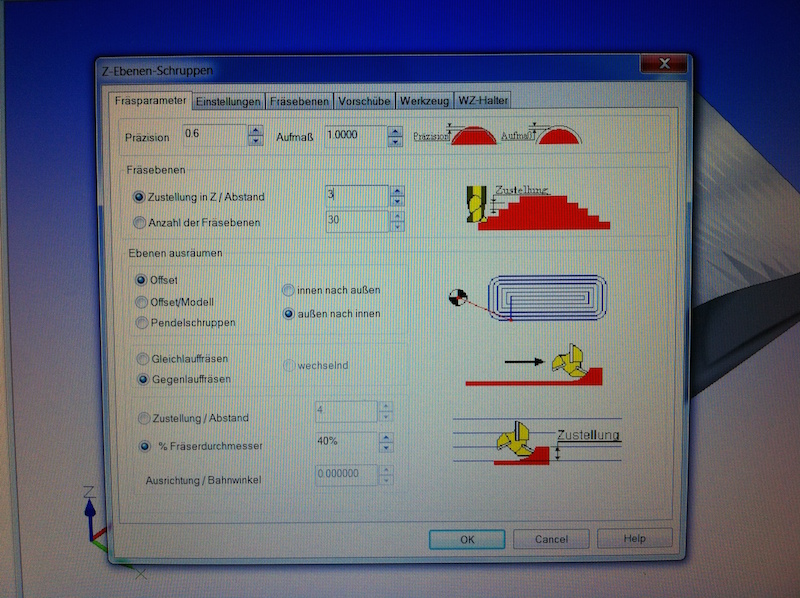
Milling Parameters
Fräsparameter in this panel you can play with the precision of the rough cut, extracting your material quickier, (if dependes with which material are you using for milling.)
Abstand: is the meassure between the each pass, that means that each pass is around5 mm, if this is wood or metal you can consider a less distance, in order to avoid damages in the bit (middle of the bit diameter.)

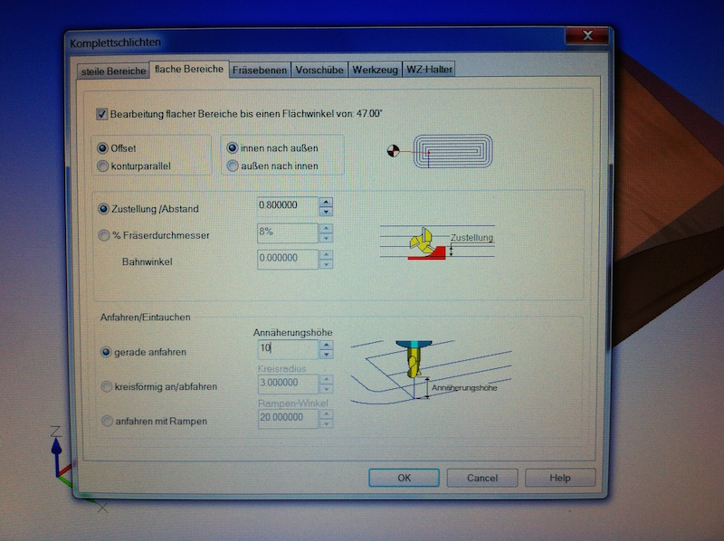
Offset
Annährungshöhe ist the distance between the material, that the bit taketo go to the other pass, in this occasion we use a small distance in between of 5 mm, in case of milling and other material to avoid some damages please increase this distance.
(for this traces the machine moves 1000 rpm, it is slow, it means if you have a big distance it will takes more time to mill the hold piece )
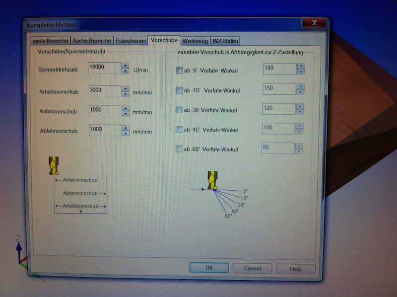
Vorschub / Speed and Feed rate
You can change the settings for both jobs to have better results (faster , finer,) but you can work with the same settings
Spindeldralzahl: spindle speed
Arbeitsvorschaub: the speed when the tool is doing the passes in the material
Anfahrvorschaub: speed, when the tool going inside in the material

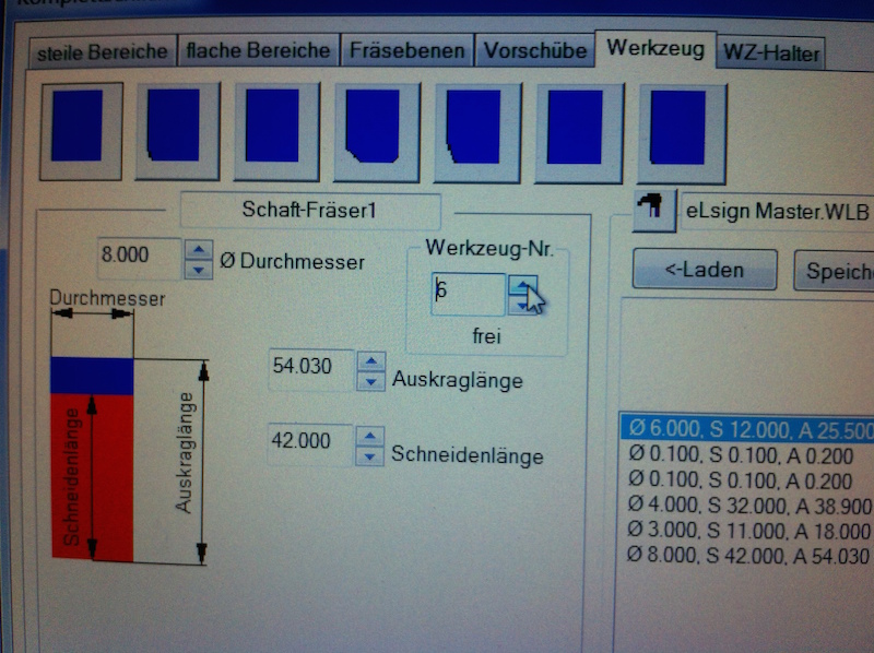
Tool panel
in this panel you can select one of the bit that we have in our Fab Lab. In case that you change your bit You have to set the new parameters.
You can select which kind of bit you are using that depend which job are you doing, (cutting, engraving, pocket, finishing, etc).
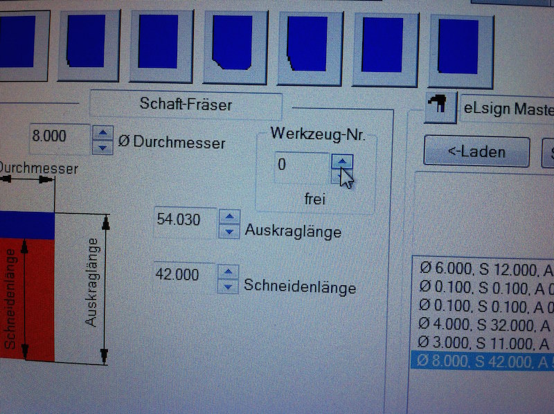
Durchmesser: diameter
Auskraglänge: projection length. the length between the coil and the end of the tool.
Scheidenlänge: sheath length. Is the length of the spiral of your tool
Werkzeug Nr: If your machine can not change the tools automatically and has only one tool please select the tool "0".
if your machine can change the tool automatically , please verify it in your machine- which number is the tool that you want to use.
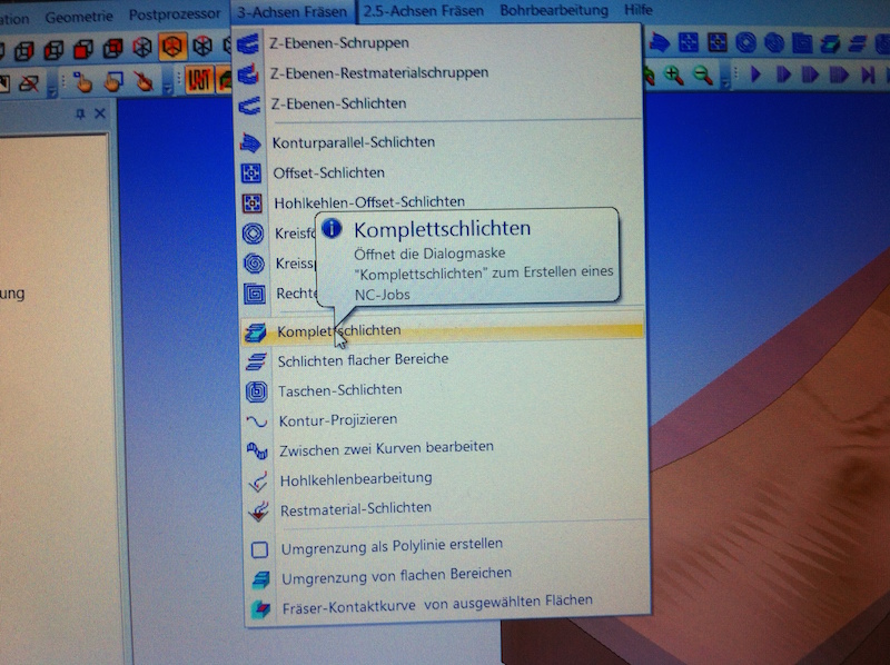
Fine Cut
Komplettschichten: milling the rest of material
number of the number of the bit

Milling parameters
For a smooth surface you can select around 0.02 mm to have an extremely soft surface
Offset 2
In this window you have a second offset that work for right lines
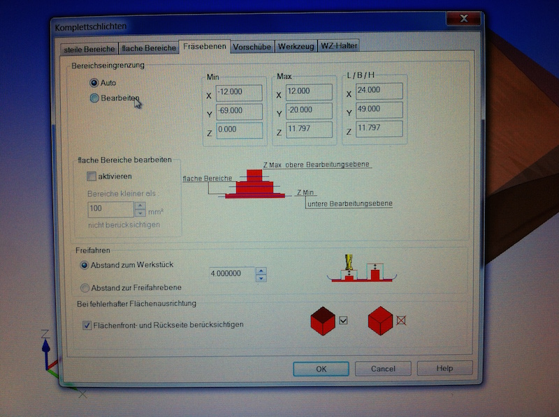
Milling Layers
Bereicheingrenzung: reduce the area of milling, to decrease the time of the job , and to work with short tools, you can use this option.
Tool
Verify and select the right tool number if your machine has multiple tools.
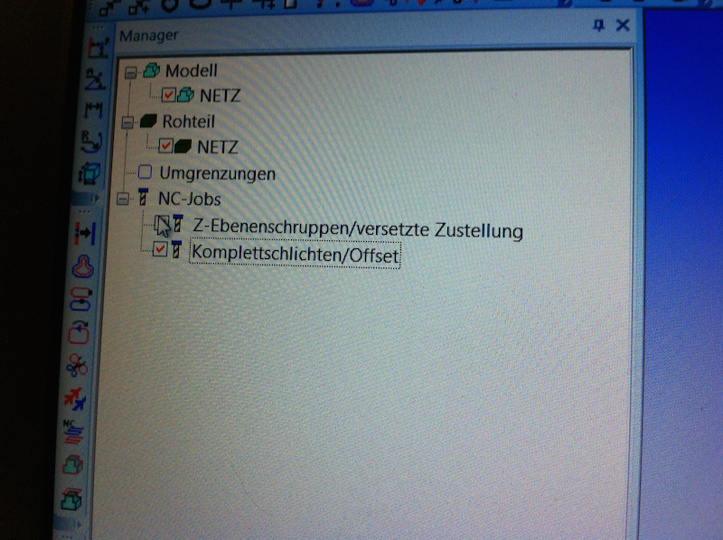
Almost ready to mill.
At this moment we have 2 jobs the rough and the fine milling jobs. please check both jobs. in order to generate the G code in the postprocessor.
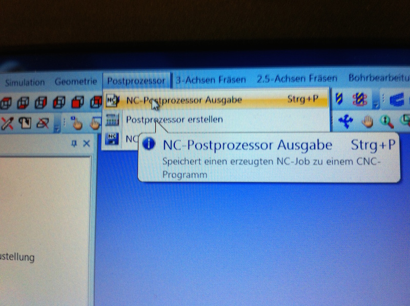
Post Processor
Select the Postprocessor ausgabe, afterward you will see window with to option
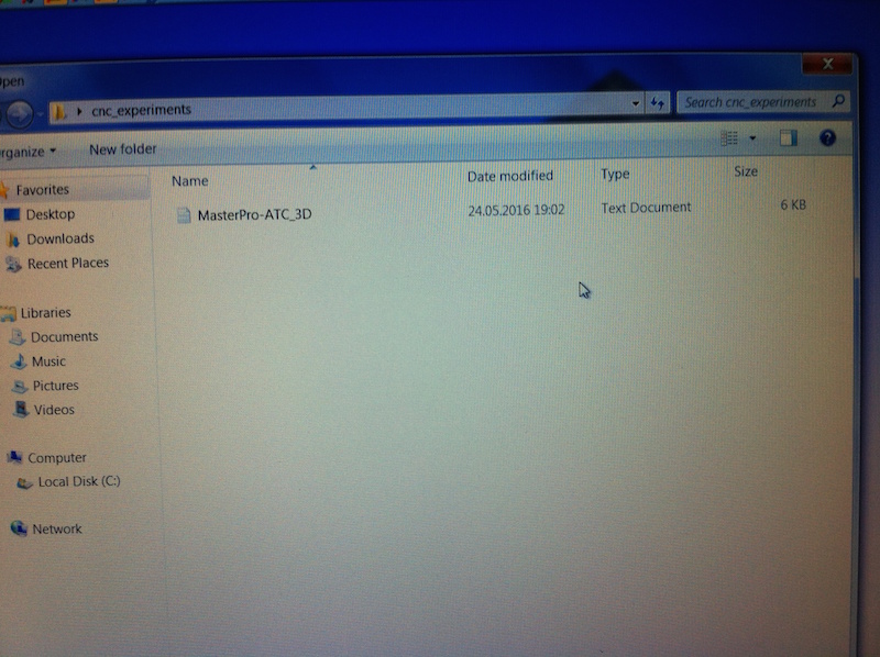
Driver: 1. select the driver for the postprocessor for our machine e(sign easy master pro, which is MasterPro ATC_3D. 2
Select the partition that you can save your data and the name it
G-code ready
After the Postprocessor generates the G-code, you can proceed to simulate the milling process with the play function in the top of the window right.
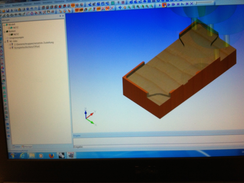
Simulating the process
Diameter
Editting 3D Scanning
as model I select my arm which is the first model that I i scanned , I wanted to test the acurancy of the scannern an also experiment with the material, for this assigment i get insight of the 3D Scanning editing

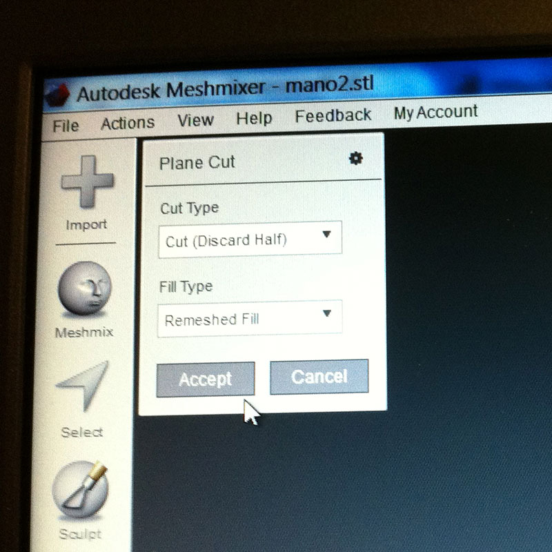
Meshmixer
For smooth your model you can press the option Select and transform your model a little bit.the idea is not damage the anatomy of the hand , only to smooth the edges.
To cut the hand in a right edge you can use the “Plane Cut”.
Symulating the process
for cutting the hand in a right edge you can use the > Plane Cut

Offset
In case of doing a negative form you can generate an offset expanding the dole homogeneously.
you can see that there is overlapping of forms. that will be difficult to reparet.
You can open your model in the Computer of the machine E(sign Easy Master Pro go to Auto > Load, select your model. Machine Referenzieren > home X and Y depending where is the beginning of the material and the model. set the Z Home, with the Sensor in the top part of the machine
First trial / Adriana's arm - Hand
As model, I select my arm which is the first model that I scanned , I wanted to test the accuracy of the scanner can also experiment with the material, for this assignment i get insight of the 3D Scanning editing
I decided to do the negative form of my hand , which was not really successful, the idea was to create the positive , and compress both in between, in the following pictures you can see the results.
I used Styrene for milling the model, Because is cheaper in comparison to the urethane and enough soft to mill in the CNC machine

Rough Cut
1,5 mm between the pases.

Protecting the hand with "holzheim"
Holzheim: product for paste wood !, it was not enough you have to be careful that the product is homogeneously spread in the model, otherwise will take years to be dry.
Protecting it wih
Because the Resins that we use could react in contact of the water. also you can apply a little bit vaseline or oil for separating the resin with the alufolie

Components for casting
Both components are Polyurethane - casting resins flexible, it take like a 30 min to solidify the material
For Component A and B you can use 50% to 50%. for more information you can see the Datasheet

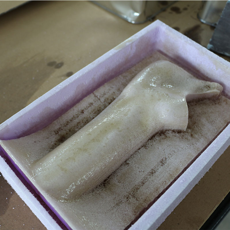
Making the positive
As we see the model have some problems due to the position and anglen of cutting, it makes ta that the am is deep but in the fingers there are less material.
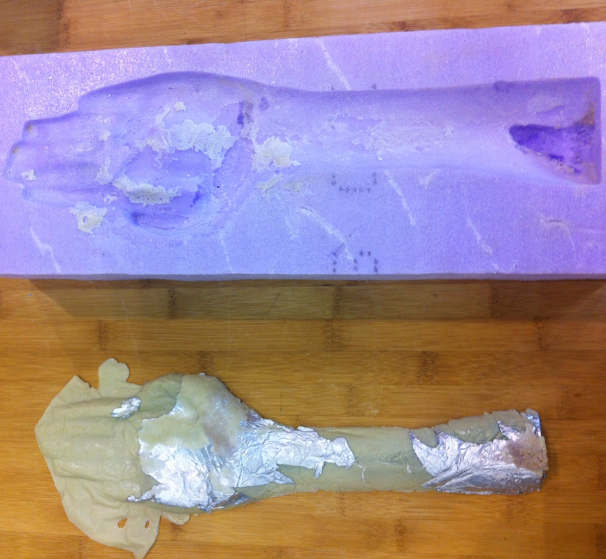
Positive and negative
The Polyurethane made a wire surface, destroying the cnc Model. :( , some reflection I have a "killing insects Tool!"
I decided to do a new model that illustrate more the form of a orthotics.
Orthotics with natural fibres
Considering that the other model was the replication one of the part of my hand , I decide to modify it, doing some split boolean functions in the program Rhinoceros, I look som basis of the Designing of orthotics, (in this scenario the application for the immobilization of the palm and inferior arm)
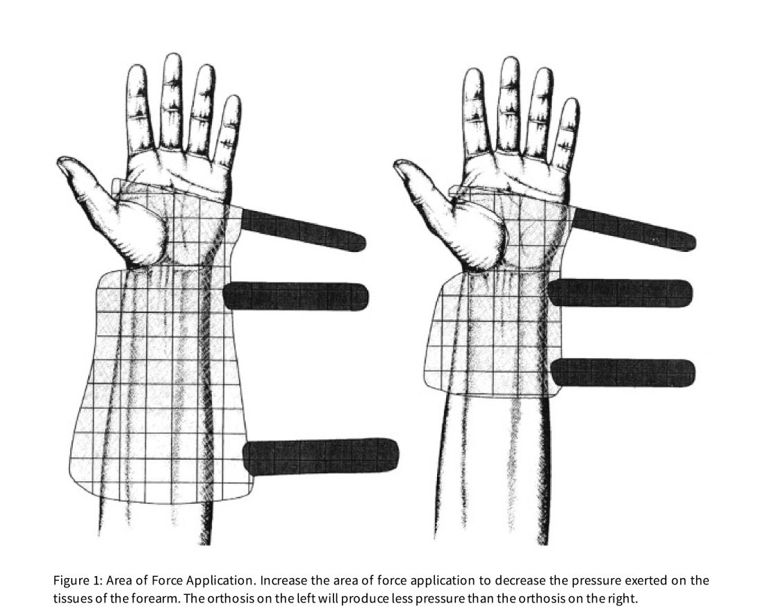
Designing a splint Orthotics
Reference of the book: Hand Splinting / Orthotic Intervention: Principles of design and fabrication. You can find more Information in the following Link.

Rhino model
After the cutting

E(sign Master ProSoftware
During milling.

Glad surface
with epoxy, givin a finishing to the model
the material is a little bit damage only in the edges , is this is not a problem. because afterwards I cut it for doing applying the composites
Proccess working with the milling machine.
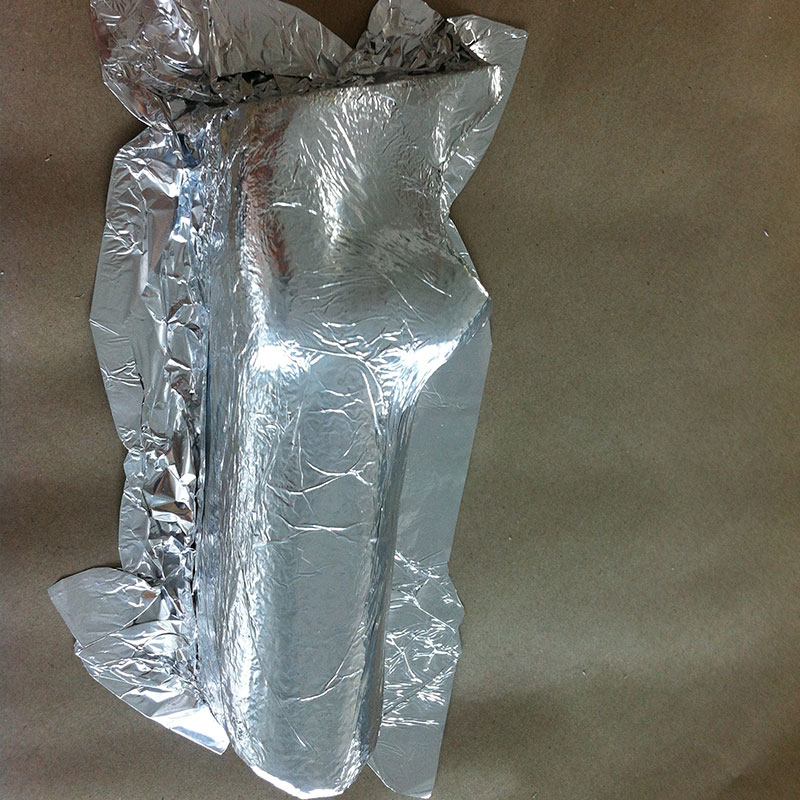
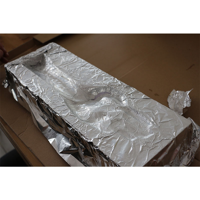
Covering with alufolie
In case if you will use again and separating the materials.
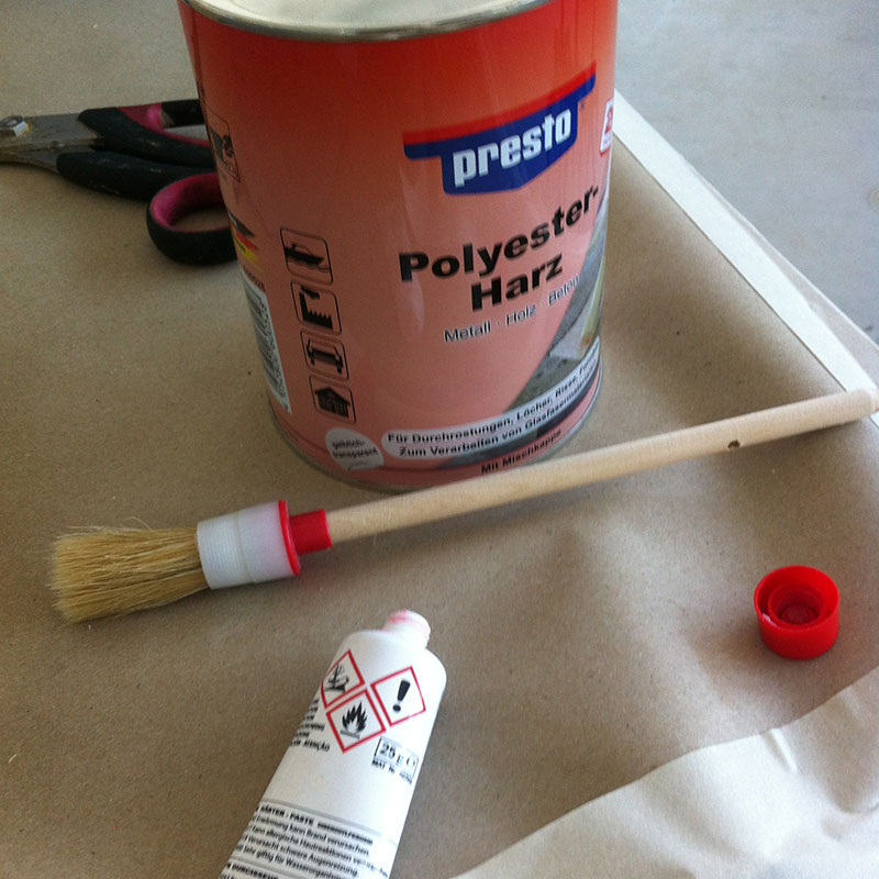
Components
Poliester Harz 10: 1(a little bit)
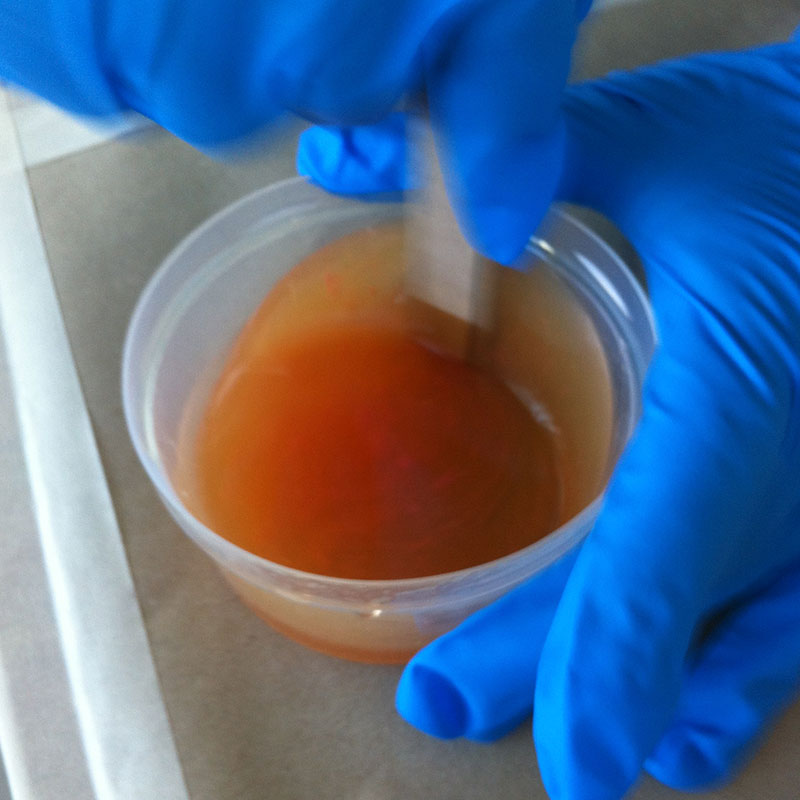
combining the components.
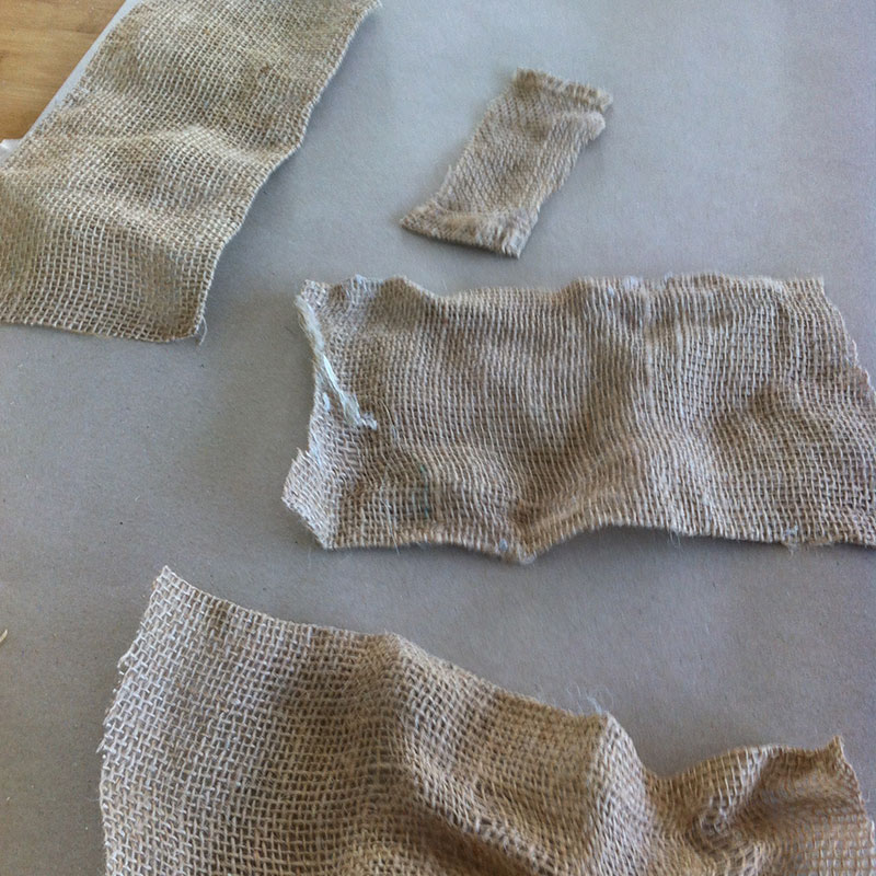
I use around 3 pieces for doing the model
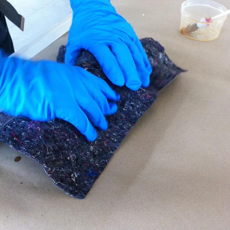
Preparing for the vacuum machine
Always cover the model to avoid some damages to the membrane of the machine

before cutting
I thought tha I could cut the for ofthe fique , but i need this space and givng the hole form
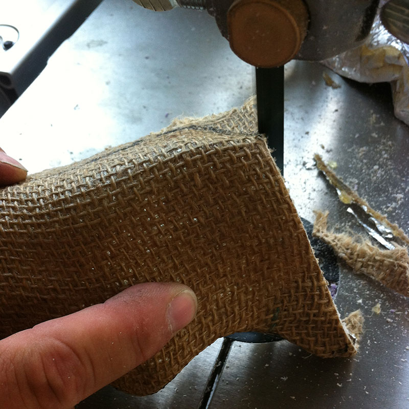
cutting
you can cut the the composite with the band cutting machine.
Some Videos
Process Vacuunn
Only with a couple minutes, I left the model 20 minutes in the vacuum and it was ready
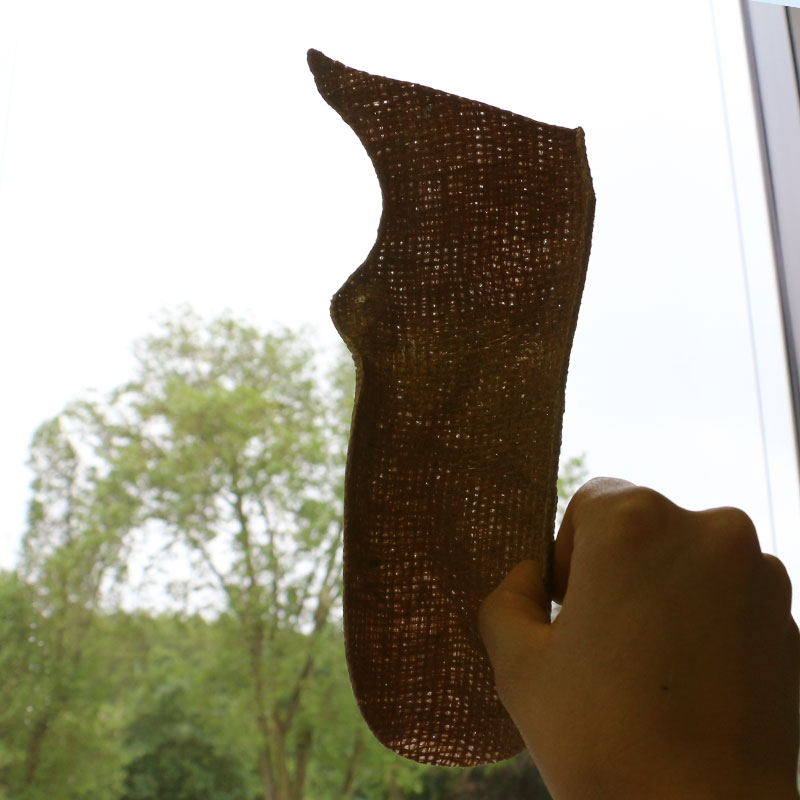
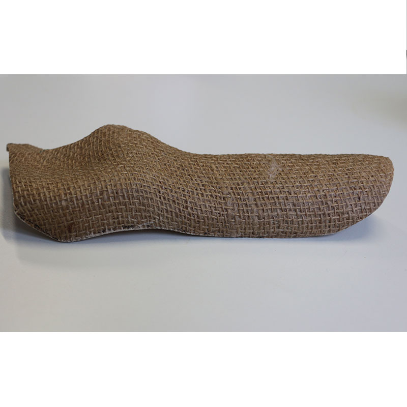
texture lightness and frendly
implementing this material, gib this a totally different appearance in comparison of the prosthetics and orthotics, it has still holes, which is able the transpiration and friendly texture
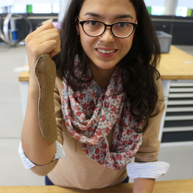
fiting
It tis as an accessory but not more a extra element from my Hand

Conlusions
I am so happy that the the functionality of the composites , it is still flexible , but in the same time strong,it is a visual element for showing as it is , with a really low cost:
Foam: 2 euros
Sack: 1 euro
Polyester: around 5 euros more or less !!!
Nice exercise also repetition a lot of work but give me a great gratification !