Using as input the Gyro GY-521 board
Where you can find this component: http://www.banggood.com/de/
Datasheet
Testing the gyroscope with an arduino IDE:
I checked some websites on the internet to test the gyroscope with the Arduino. You can find some references on the following websites: http://playground.arduino.cc/Main/MPU-6050 http://playground.arduino.cc/Main/MPU-6050 http://playground.arduino.cc/Main/MPU-6050#short http://archive.fabacademy.org/archives/2016/fablabyachay/students/321/weekmain.html http://diyhacking.com/arduino-mpu-6050-imu-sensor-tutorial/ http://www.geekmomprojects.com http://fritzing.org/projects/mpu-6050-board-gy-521-acelerometro-y-giroscopio
Following this tutorial I could read and understand a little bit of the funtion of the Gyro, you can watch it here: (http://www.instructables.com/id/MPU6050-Arduino-6-Axis-Accelerometer-Gyro-GY-521-B/) Photo reference: http://www.instructables.com/id/MPU6050-Arduino-6-Axis-Accelerometer-Gyro-GY-521-B/) In the following picture you can see how you have to wire both boards. I the first plan you have to connect the Arduino with the Gyro. In this case, the pins that I used for the Arduino can be connected in the same for with microcontroller ATMEGA 328, that is used in the Satsha kit.
Noticed: all the red cables are VCC (+5V) and the black cables are GND, check this carefully when wiring up your circuit. The breakout board comes with pins but requires soldering.
*** For your own learning: the gyro module communicates with the Arduino through I2C serial communication via the serial clock (SCL) and data (SDA) the MPU6050 chip needs 3.3V but a voltage regulator on the GY-521 board allows you to give it up to 5V For more information on the module there is a great resource on this page in the Arduino Playground (future I have to implement a voltage regulator)
Code The accelerometer and gyro values are called the "raw" values. This is just as with the other accelerometers and gyro sensors. A more sophisticated application is using the DMP to retrieve specific computed values from the sensor. The Short example sketch on this page is a very short sketch that shows all the raw values. Click "Get code" at right, below the sketch, and copy it into a sketch. The Example sketch (base code) on this page is also just showing the raw values, but it is an attempt to be a complete base for more functions. For serious use of the MPU-6050, Jeff Rowberg has done an excellent job. See his I2C lib: http://www.i2cdevlib.com/devices/mpu6050 Or the latest code on Github: https://github.com/jrowberg/i2cdevlib/tree/master/Arduino/MPU6050 The FreeIMU library includes the MPU-6050 code from Jeff Rowberg. The FreeIMU library: http://www.varesano.net/projects/hardware/FreeIMU To start with the MPU-6050, see the page of InvenSense: https://www.invensense.com/mems/gyro/mpu6050.html For better understanding, I looked on the internet for some references for changing the code and mapping the RAW: http://www.i2cdevlib.com/forums/topic/4-understanding-raw-values-of-accelerometer-and-gyrometer/
After the connection of the board of the gyro1 x GY-521 and the Arduino you can proceed to load the program into your Arduino IDE and test this function. I used the library i2cdevlib from Jeff Rowberg for having access to the Digital Motion Processing (DMP). Once unzipped, find the Arduino folder within it and copy the two folders "I2Cdev" and "MPU6050" over to your Arduino "libraries" folder in the following (for mac) Documents\Arduino\libraries (for Windows Programs Files x 86).
Then open the Arduino IDE and in the examples section, you should find MPU6050_DMP6 within MPU6050. Open it, plug your arduino in, select the appropriate COM Port and upload the sketch. In the Serial Window, select a baud rate of 115200. You should be prompted that the MPU6050 connection was successful. You can test the data collection by typing anything in the text bar and pressing enter, the data should start showing up. In the following video you can see how that works.
Developing a Gyro SK (Satsha Kit)
In the first step I look the github of the sashakit, you can find it in the following Link: https://github.com/satshas/satshakit
Using the Satsha kit I could modify to the satsha using the original layout and connecting directly the Gyro board to the satshakit in this case I modified the satsha doing a soket for the Gyroscop GY-521 and I leave the some extra pins , in order to use in the future board connecting some output devices.
Components.
Microprocessor: ATMEga 328P
Capacitors: 2x 100 nF 2x 22pF 1x ´0uF 1uF
Resistors: 10 K Ohm 2 x 499 Ohm
Switch: 1 Button
Crystal: 16 MHz
LED: Green Yellow
Editing the board in the Eagle: For editing the board I have to do some modification in the schematic in order to separate the pins for the Gyro, giving after that enough space in the job data , also because the traces are extremely thin in me, this is the first time that we solder such as thin legs of the microcontroller ATMEGA Working with Fab Modules with the Roland MDX40a This is the first time that I work with the fab modules and the Roland Milling Machine to do Circuit boards
.
Using the Fab Modules for the our Roland MDX40a
Some of the difficulties of using this machine was To have the right adapter and bits to use the machine, to level the platform 1 using thick double side scotch tape stead using screws and nuts, adequating a special platform for the doing more that one boards.
In this case I did a special data cutting a bed from MDF 6mm, The data as attachment. For this case We discovered that the milling board are bended in this case we could avoid this problem with the screw, but nevertheless the result was a bit better. I test the deepness of the bit in the area of the bit when I discovered the right deep in the 4 corners of the board testing in rectangle if the cooper was out , as you can see in the following picture.
For using this system your computer should will connected to the network "FabLab2" wifi connection Due to our machine is connecting in a parallel port and doesn’t accept the serial port to the computer, we use only one computer to establish the communication with the roland and the fab modules, In case if the communication doesn't work, please go to the computer near to the Roland and enter the password that is a pasted on the computer.
Enter ! In your computer you have to select the the wifi network for stablish the local connection server in this case FabLab2, after is open the Fab Modules with the following Address: ‘... After that you can open in the fab modules website the input in this case PNG, Process: milngthe machine> Roland Milling> method > traces > Then you have you image open in fab modules
Fail trials:
It the deepness s not enough you can edit your file in Photoshop or gimp deleting the traces that are well done and keeping the traces that you have to do deeper. My first Problem: the tool 1mm diameter, has an egle of 45 degrees, in the following phases the most of 1 traces has out leaving a extremely thin espace and damaging the circuits ,in this case I have to do a new one. My second problem: don't cut directly the data in Photoshop because the fab modules will do a cut line in te part of the traces that ar well doing , for making and isolation in the traces.
After several trials looking for the best board, according with the SathaKit developer: Daniele Ingrassia, he found the board well :
Soldering
After several trials soldering I was the TERROR !!! 1. Using the ground as soldering increase the probability of the son of the connection are connecting with ground causing a short circuit. OFFSET: we did only 1 line of offset it means the separation of the copper and the circuit was to small also for the soldering spine that we have. fehlt the soldering. Other i change the resistor 10 Kohm for 1 ohm, burning the microprocessor In the 3 trial soldering I will again select the component and carefully test the hole traces In this tame the platine works well , but the traces are really tink, that means thast i have to be really carefully in the selection of the components and in the soldering First clean the board of the extra cooper , for avoiding the short circuit, 2 . make the holes. In this time I tried really carefully first of all touching the board with the bit , and slowly going down wit the bit ,
Returning to te final project
After the first visit of Frank Miller 1 june (please see schedule), I realize that I don't really need the Gyroscope for the arm case. because I could solve this function with a mechanical solution and also because in this case was a priority to stabilize the forces of the hat making and splint , and focussing the movement in the fingers, And the interaction of the fingers. How I can activate the motors? In this case I thought about the other sensor which is the MyO wer This sensor reads the Input devices: Integration of a gyroscope with an accelerometer in order to recognize the ROM (range of motion) values. With mapping these digital values, I can recognize the over angle that the patient has this sensore, my task in the programming is:
* Measuring the MYO of the muscles, in order to provide the enough information to the microcontroller. * * * Sending the information trough the microcontroller to an output through an actuators (Smart memory alloy or motor) providing the right position of the limb.
MYO (electromyography) and Myo ware
this is a sensor that permits the measuring of muscle activity. Measuring muscle activation via electric potential, referred to as electromyography (EMG), has traditionally been used for medical research and diagnosis of neuromuscular disorders. However, with the advent of ever shrinking yet more powerful microcontrollers and integrated circuits, EMG circuits and sensors have found their way into prosthetics, robotics and other control systems.
The use of this sensor permits the mapping of the ROW values. From a very sensitive lecture until the very strong movements depending of the calibration
As you can see in the pictures of the data sheet , I have to evaluate the most round value , which you can mapping with the serial plotter of the arduino.!
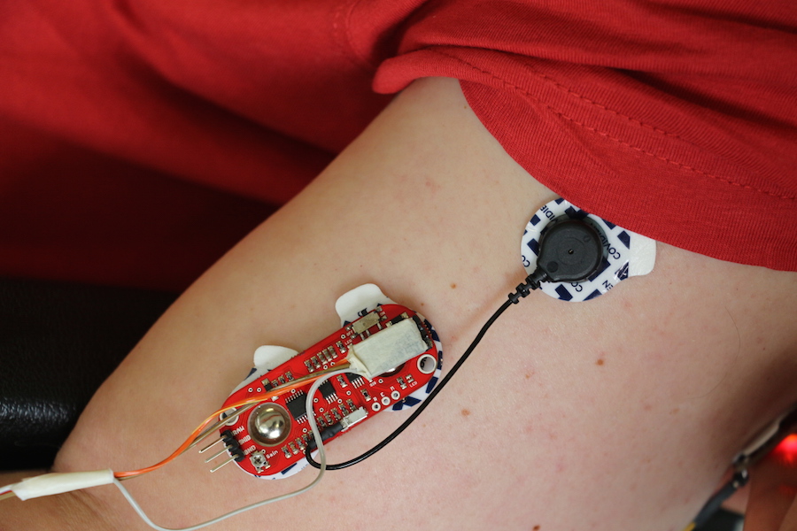
My first trial is the recognition of the Myo: I used the myo of mapping the row from my Biceps ! afte for triceps As you can see in the following picture , I take some precautions and proceed to connect first of all, trying with the arduino IDE board the programming of the sensor looking for the variation of my EMG values variation. In the first time I didn't recognise the connection of the black electrode l As the datasheet picture shows, the black electrode is connected at the end of the muscle. And the other two electrodes are connected in the middle of the muscle , you can position the sensor for better results of the lecture.
After that, I could see that the sensor works really well, and second that I could see the variation of the values in the serial plotter. And in the serial monitor, In the serial monitor I could see the exactly the values of the variables, that represent the behavior and movement of the muscle, # In the serial plotter. Which is a new option of the arduino IDE software, you can see the quality of the movement showing in this first time the correct placement of the sensor. In the sensor we can see different kinds signals which is basically the RAW and the EMG signal. For those ones we have to refine this signal due to the rectified and integrated Signal.
The wiring the Gyro SK Satshakit
The sensor works from 3- 5 V , That mean you need GND connection, VCC connection Analog pin Connection . this sensor works as a analog Pin PMW pin,that means that this is a similar a, as the potentiometer works. After connecting this in the GYro SK works well because I took the pins that I designed for the Gyroscope socke, in this case I aly need the ground VCC an the A0 pin. In the first case I though that the sensor only works with the 3 V , For work with the sacha kit it doesn't have the power converter , that means that I how to use an external one After connecting this in the breadboard I see that the Myo ware doesn’t works, Reason The sensor is controlled by 5 V, that means that i have to take out the voltage regulator, after that i changed the Pin because it does work stun much well, Clean the surface of use the sensor and leave a little bit wedd help for the conductivity anr lecture of the e values. (Alcohol or oil) After connecting the sensor with the 5 volts and using a little bit alcohol works well!! I could proceed to continue to te motors controlling.
Testing the Myo ware sensor to the patient. Identification of the muscles Lecture of the integrated values In order to find his Threshold
#include
Servo myservo;
const int MyoValue = 250;

void setup() {
  // put your setup code here, to run once:
myservo.attach(9);

}

void loop() {

  int value = analogRead (A0);
  if (value < MyoValue)

  {
    myservo.writeMicroseconds(800);

   }

  else
  {
   myservo.writeMicroseconds(2250);
  // put your main code here, to run repeatedly:

  }
}
//#include
#include

#define MYO_PIN_BICEPS A1
#define MYO_PIN_TRICEPS A2

#define MOTOR_PIN_INDEX 6
#define MOTOR_PIN_MIDDLE 5
#define MOTOR_PIN_THUMB 9

#define THRESHOLD_MYO_BICEPS 300
#define THRESHOLD_MYO_TRICEPS 300

bool holdIndex;
bool holdMiddle;
bool holdThumb;

VarSpeedServo servoIndex;
VarSpeedServo servoMiddle;
VarSpeedServo servoThumb;

int myoValueBiceps;
int myoValueTriceps;

void setup() {

  Serial.begin(9600);

 holdIndex = false;
 holdMiddle = false;
 holdThumb = false;

 servoIndex.write(0,50, false);
 servoMiddle.write(90,50, false);
 servoThumb.write(0,50, false);

 servoIndex.attach(MOTOR_PIN_INDEX);
 servoMiddle.attach(MOTOR_PIN_MIDDLE);
 servoThumb.attach(MOTOR_PIN_THUMB);

 Serial.println("ok");

}

void loop() {

  myoValueBiceps = analogRead(MYO_PIN_BICEPS);
  myoValueTriceps = analogRead(MYO_PIN_TRICEPS);

  Serial.print("biceps:");
  Serial.print(myoValueBiceps);

  Serial.print(" triceps:");
  Serial.println(myoValueTriceps);

  delay(100);

  if(myoValueBiceps > THRESHOLD_MYO_BICEPS)
  {

    if(holdIndex == false ) {

      servoIndex.write(70,50, true);
      servoMiddle.write(20,50, true);

      holdIndex = true;
      Serial.println("index hold");

    }
    else{

      servoIndex.write(0,50, true);
      servoMiddle.write(90,50, true);

      holdIndex = false;
      Serial.println("index release");

      }

  }

  if(myoValueTriceps > THRESHOLD_MYO_TRICEPS)
  {

    if(holdThumb == false ) {

      servoThumb.write(65,50, true);
      holdThumb = true;
      Serial.println("thumb hold");

    }
    else{

      servoThumb.write(0,50, true);
      holdThumb = false;
      Serial.println("thumb release");

      }

  }


 /*

 value = analogRead (A2);
 value2 = analogRead (A1);

Serial.print("v1:");
Serial.println(value);

Serial.print("v2:");
Serial.println(value2);

  if (value > MyoValue)

  {

    Serial.println("move1");
    myservo.write(90,50, true);
   myservo.write(0,50, true);


   }

  else
  {
    while(value > MyoValue)
     value = analogRead (A2);

  // myservo.writeMicroseconds(2250);
  // put your main code here, to run repeatedly:
  //myservo.write(0,50, true);

  }

 if (value2 > MyoValue2)

  {

    Serial.println("move2");
    myservo2.write(90,50, true);
   myservo2.write(0,50, true);


   }

  else
  {
    while(value2 > MyoValue2)
     value2 = analogRead (A1);

  // myservo.writeMicroseconds(2250);
  // put your main code here, to run repeatedly:
  //myservo.write(0,50, true);

  }

 */
}
Future Works
Develop a low cost sensor for lecture of the MyO that provides a daily, which have another system for attaching it with the arm.