
W15 - NETWORKING AND COMMUNICATION
This week assignment was: design and build a wired &/or wireless network connecting at least two processors.
For this week I decided to make my LED board to communicate each other, sending and receiving information between two similar boards.
So basically I wanted them to be twins from each other, it means that when I point the laser to one of them, it transmit the information to the other one, so they end up lighted the same way.
Electronic Board
Before that, the first thing I did was to make a new board, with pinheaders for communication.
The first change that I had to make was because I need at least two pins of the microcontoler to use as RX and TX. With that I would loose one Row and one Column of LEDs, then they would be 3x3 and not 4x4 as the previous model.
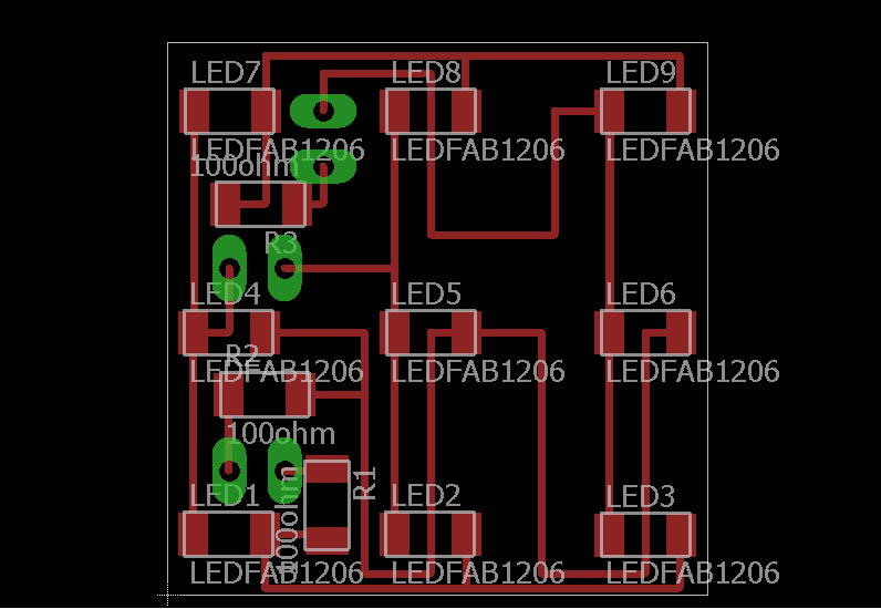
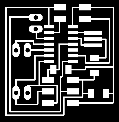
I followed the previous boards design but changed some of the pins of rows and columns to facilitate the traces routes in eagle. I tried to make several board designs until get one that I like, but I ended needing one 0ohm resistor to make a bridge between traces that cross each other. So this is how my board design looks like:
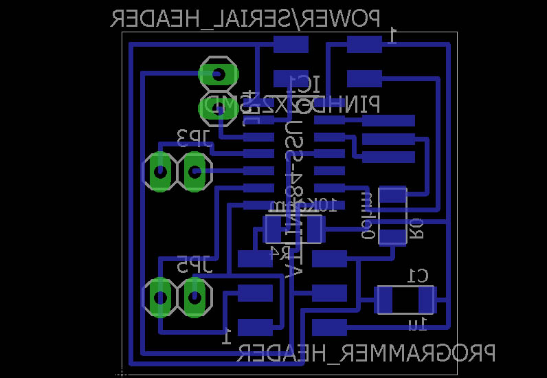
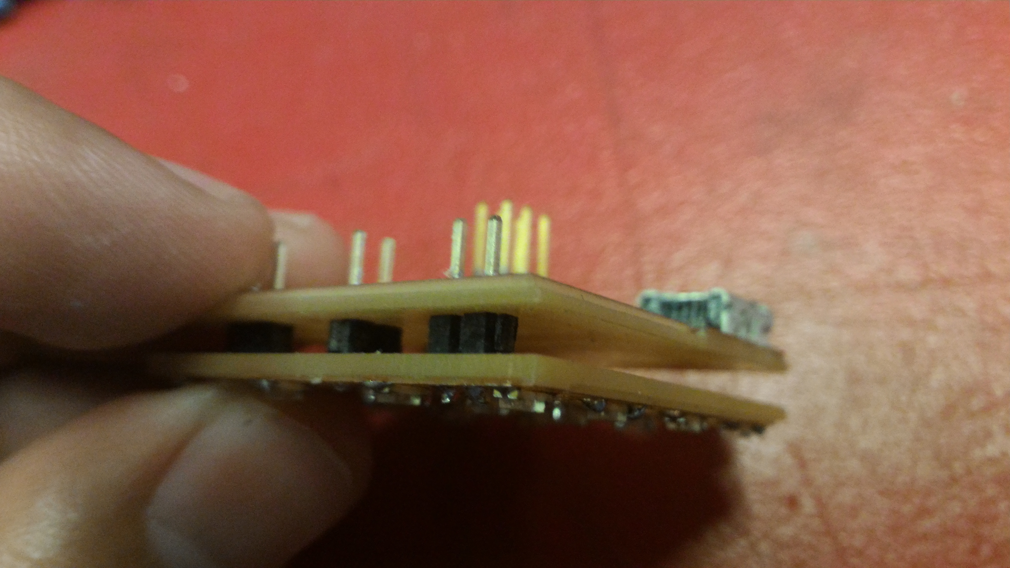
After design the board, I went to mill it at the Roland Modela. Note that I designed a double-sided board. As we do not have those boards, what I did was to solder some pinheaders connecting the two boards.
When you are designing like this, you need to remember that the bottom image exported from eagle need to be flipped using gimp or Photoshop. I used Photoshop CS6 to edit my images when necessary.
A different process here is that you need to make holes in the board so you can insert the pins. I put the holes in the same image of the board cutout, so you mill it as well. Here is how the files prepared for milling looks like:
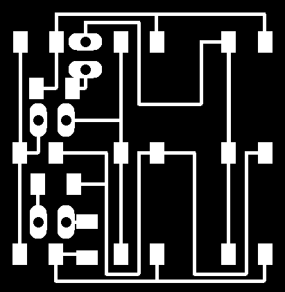
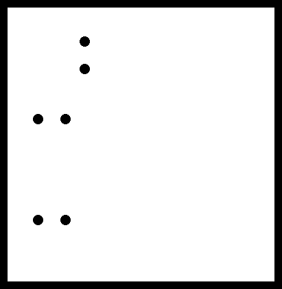
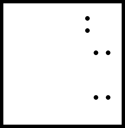
See that the bottom files to mill are horizontal flipped compared to the print screen from eagle showed before.
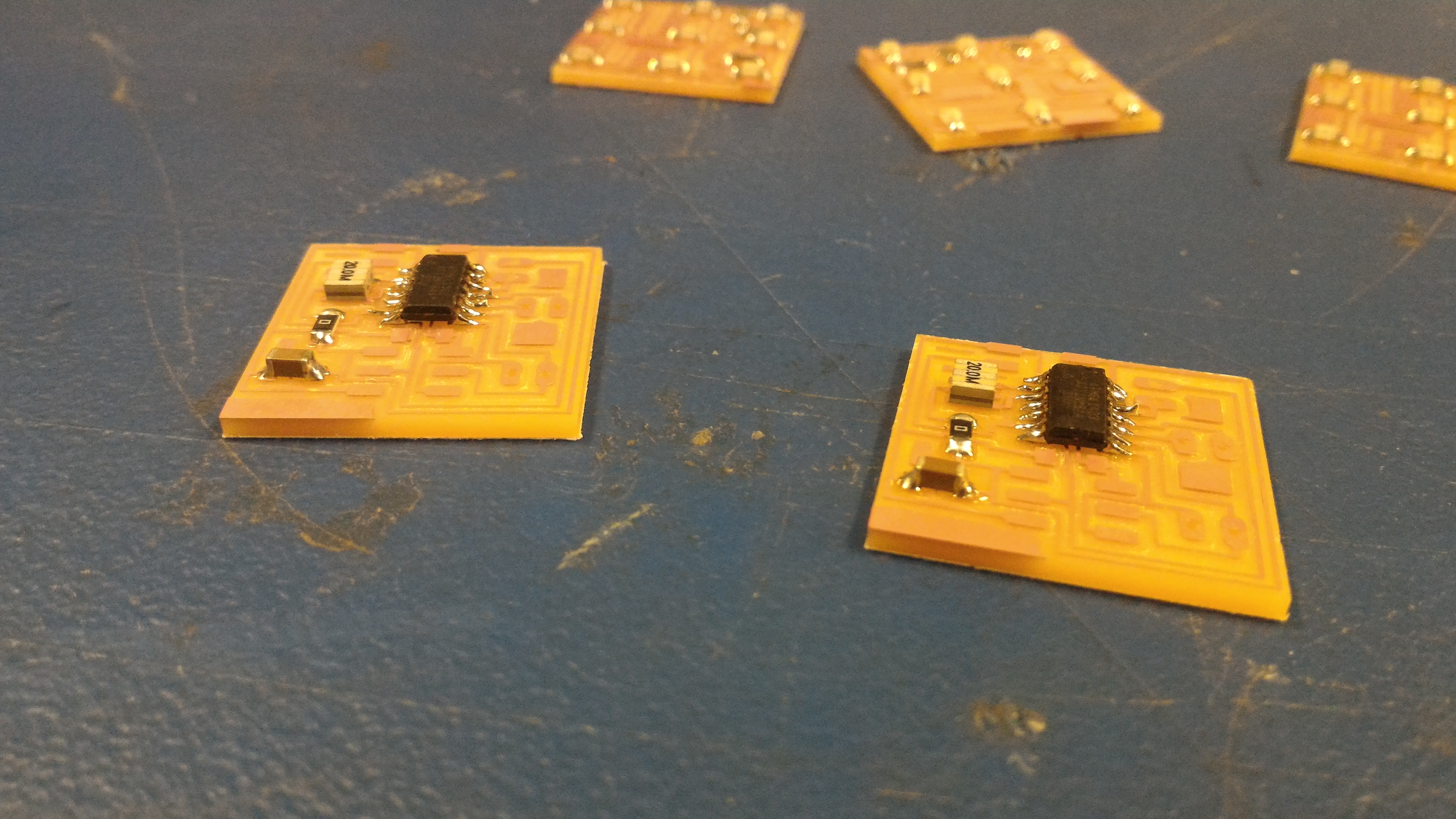
So I milled the 4 boards because I wanted to make two LED nodes to communicate each other, and started to stuff them with the components. Nothing new here, just solder all of them in the correct place.
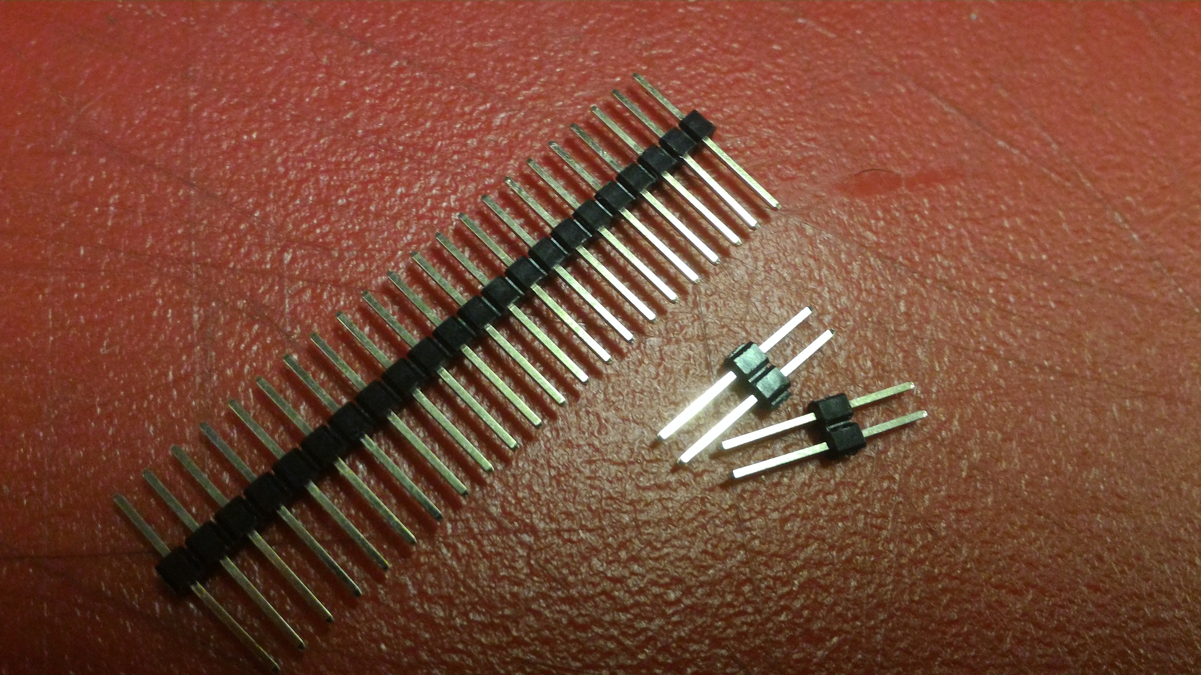
After solder the components, solder also the pins connecting the two boards. Here how are the pins I used and how I solder them together.
Programming and Communicating the nodes
Once my board was done I started to work with the programming part. In the W14 assignment (output devices) I showed a similar LED matrix working and how I connected them but at that point I was not communicating to the computer. Here my goal was to be able to communicate from the computer to the board.
So I started to research to find out how to serial communicate between my computer and my board which uses an Attiny84. I found that the easiest way was to include a new library, called "SoftwareSerial.h" (see http://www.instructables.com/id/ATtiny85-ATtiny84-Analog-Pins-Serial-Communication/step3/Using-SoftwareSerial-for-Communication/).
The main steps are:
1. Include the library with your sketch by using the #include at the start: #include "SoftwareSerial.h"
2. create variables for the function and call the function:
const int Rx = 7; // this is physical pin 7
const int Tx = 0; // this is physical pin 0
SoftwareSerial mySerial(Rx, Tx);
3. In setup() configure your pins and se the baud rate:
pinMode(Rx, INPUT); //set Rx as input (receiver)
pinMode(Tx, OUTPUT); //set TX as output (transmitter)
mySerial.begin(9600); //baud rate for communication to the computer
Then start the programming.
To be able to send the information I need to organize it in an easy way to send it through the serial port. I wanted to send the states of the LED (on or off) as binary states (0 or 1). Then I realized that I have 9 LEDs, this is one bit bigger than a byte and here the challenge begins.
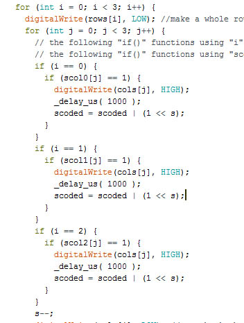
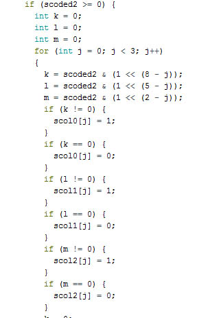
Therefore, to send the information I need to organize it. To make it I used the same "for" routines that I light up the LEDs, to store 1 or 0 in a new variable, and this variable will be sent through the serial port. In this case, to be more effective I needed to use bitwise operators. I take some time to really understand how bitwise operators work, but following the Arduino references pages and reading it very carefully, I could solve my problem. So if you want to understand better what I did, I advise you to read it too:
So I created this new variable "scoded" and initiate it with 0 (zero). Whe the laser pointer is pointed to it, it will both light up the LED and add a 1 at the correct position. I also used a variable that I called "s" which is the LED position, and help me on the bitwise operations on putting the "1" status at the correct place. I initialize "s" with 8 and subtract it until 0 in the main "for" routine.
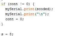
Then to send the information I just use the function: "mySerial.print(scoded);" where mySerial is the name I put at the beginning, also I send "mySerial.print("\n");" where the "\n" means that the information is complete. Also I put this function inside a "if" that checks if a LED was pointed. So it just send information if a LED changed it state. After this I reset "s" back to 8 to be prepared for new data.
To receive information I did basically the same thing but instead of transform the information from the LED states variables to one new variable, I need make the reverse path. Transform one variable received through the serial port into the LED states variables. So to read from the serial port you need to use the function "incomingByte = mySerial.read();" As the information I need to send is bigger than 1 byte (actually 2 bytes) I need to set something to know that the information is complete sent. So every time on information ends with '\n' I will know that it its ends.
This is how this part of the code looks likes:
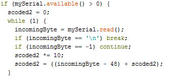
An important thing about this part is that I needed to decode the information to get the right data. When you send a information through serial, it send it as character, it means the when I send the number 0 (zero) it is actually sending 48 (according to the ascii table). So I need to transform it back to 0 and to the correct standard I set before to state arrays for the LEDs.
Again, I used the same bitwise operators and some if functions to detect when a bit is 0 or 1, and then insert the value in the right LED state arrays.
Here a short video of it working, communicating from the computer:
I had many troubles to set this correctly. The main learning points was the bitwise operators, the use of the ascii table (was difficult to figure out why the information I was sending was different than the expected).
I also learned that the serial monitor is very useful for debugging on those kind of problems. If you are not sure about the information being stored in a variable, just use the serial monitor and add in your programming some println() functions to you be able to see what the microcontroller is seeing as well.
My communication protocol - Addressing different boards as a Network
At the end I realized that I had basically created my own communication protocol, and that is a interesting thing to do.
The data to light up the LED are composed by 9 bits, telling the node basically which LED should be on (1) or off (0).
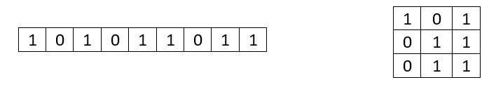
If you translate those binary numbers to a decimal number, you can find the actual information sent through the serial port, so in the case shown above is:
101011011 = 1*2^8 + 0*2^7 + 1*2^6 + 0*2^5 + 1*2^4 + 1*2^3 + 0*2^2 +1*2^1 +1*2^0 = 347
In this case, if I want to light on the LEDs marked as "1", and turn OFF the ones as "0" then I should send the number 347 through the serial port, and that is what I do in the program.
The same, if I want all LEDs OFF, I need to send 000000000 = 0, or if I want all of them ON then I need to send 111111111=511.
As I need to send two bytes of information (16 bits), but, in fact, I use only 9 bits to set the LEDs, I have 7 extra bits that I could use as an "address" for each node, this way I would be able to have 127 (7 bits) different nodes that I could connect and send data individually.
As for this week I have made only 2 nodes, I set the same "address" for each one of them, because I wanted them to be "twins". But instead of it, I can also set a different "addres" for each node, just by adding a new variable on the decoding part. This addres can be composed up to 7 bits (the 7 bits that are not used). For only two nodes all I really need is 2 bits (0 or 1).
Node 1 = 0
Node 2 = 1
What I do then, is to add the "address" to the 10th bit LED settings variable I set for each node. It means that the information that I will send through the serial port are:
Node 1 = from 0 to 511
Node 2 = from 512 to 1023
Then if I want to send information to just one of the nodes, I set the "addres" to 0 or 1. The bad thing of this is I need to harcode each node diferently, setting each of then to their specific address.
Communicating to the computer
So I got communication the computer to the board. But now I wanted to make two boards to talk to each other, without use the computer.
I realized that as my pinheaders and connections was the same for both boards, I had to figureout how to connect the transmitter of one of the boards to the receiver in the other board. I could change the wires or the programming.
I choose to change the programming, so all you need to do is to invert the Rx and Tx prins. Before they was Rx=7 and Tx=0, so you just set Rx=0 and Tx=7;
Using the computer, I just use the serial interface of Arduino IDE to send the data. See that I need to send data in the range I mentioned before (0 to 511) so the boards recognizes the information you are sending
As you connect them, they will then send the information to the other board in the correct way. Here the video:
As you can see I made this little front cover for the LEDs matrix. Basically I cut some translucent acrylic board in the laser cutter, and a very thin wood. Also I designed the board in order they to be tiled, so when I put the board side by side, the LEDs will be equally spaced each other.
Files
Here are all the files I used:
Eagle schematic: LED_siron.sch
Eagle board: LED_siron.brd
Top traces: top_traces.png
Top board cutout and holes: top_interior_n_holes.png
Bottom traces: bot_traces.png
Bottom board cutout and holes: bot_interior_n_holes.png
Arduino file (computer to board): board_computer.ino
Arduino file (board 1 to board 2):board1.ino, : board2.ino
Box files:
3x3.pdf