Interface and Application Programming
Week 13
A few years ago, I learned about Processing, a coding language with a special emphasis for the visual arts. In the context of my job I ordered quite a few books on the topic with the intent to introduce it to a larger audience in a yet to be defined timetable. My only regret was that I stopped experimenting with it but I always thought that this language was easy to learn, debug and interesting. For this assignment, I will get re-acquainted with Processing and connect the output of the serial terminal from the board that I made during the output week and move a robot that I made in said language.
Processing
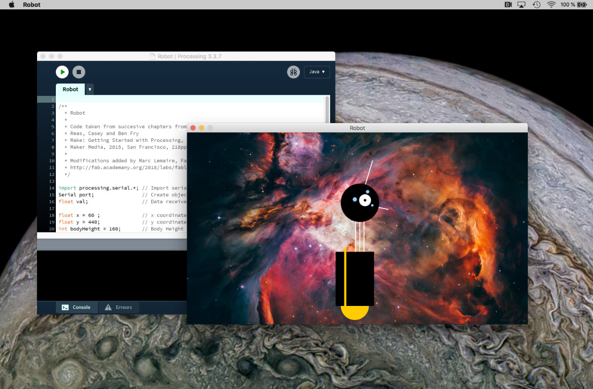
I've already downloaded the software from the website. For the tutorial, I used the book Make: Getting Started with Processing, Second edition by Casey Reas and Ben Fry, who also made other books on Processing. I find this book well written and easy to follow by examples. In this book, at each chapter's end there is an exercice in which we built a robot that is more and interactive. Although resembling the original, I did change a little the appereance of my robot.
After reading the first chapters, I have the following program where the robot follows the mouse with a physics simulation and changes it's height when the mouse button is pressed. This will be the basic block that will be added to the output module that I made.
/**
  * Robot
  *
  * Code taken from succesive chapters from the book
  * Reas, Casey and Ben Fry
  * Make: Getting Started with Processing, Second edition
  * Maker Media, 2015, San Francisco, 218pp.
  *
  * Modifications added by Marc Lemaire, Fab Academy 2018.
  * http://fab.academany.org/2018/labs/fablabechofab/students/marc-lemaire/week12.html
  */

float x = 60 ;              // x coordinates
float y = 440;              // y coordinates
int bodyHeight = 160;       // Body Height
int neckHeight = 70;        // Well, neck Height!
int radius = 45;            // Head Radius

float easing = 0.04;        // Fluid motion of the robot

void setup() {
  size(720, 480);
  ellipseMode(RADIUS);
}

void draw(){
  strokeWeight(2);

  int targetX = mouseX;
  x += (targetX - x) * easing;

  if (mousePressed){
    neckHeight = 16;
    bodyHeight = 90;
  } else {
    neckHeight = 70;
    bodyHeight = 160;
  }

  float neckY = y - bodyHeight - neckHeight - radius;

  background(0, 153, 204);               // Blue background

  //Neck
  stroke(255);                           // Set stroke color to white
  line(x+2, y-bodyHeight, x+2, neckY);   // Left
  line(x+12, y-bodyHeight, x+12, neckY); // Middle
  line(x+22, y-bodyHeight, x+22, neckY); // Right

  //Antennae
  line(x+12, neckY, x-18, neckY-43);     // Small
  line(x+12, neckY, x+42, neckY-99);     // Tall
  line(x+12, neckY, x+78, neckY+15);     // Medium

  // Body
  noStroke();                            // Disable Stroke
  fill(255, 204, 0);                     // Set fill to Orange
  ellipse(x, y-33, 33, 33);              // Antigravity Orb
  fill(0);                               // Set Fill to Black
  rect(x-45, y-bodyHeight, 90, bodyHeight-33); // Main Body
  fill(255, 204, 0);                     // Set fill to Yellow
  rect(x-25, y-bodyHeight-10, 5, bodyHeight-2); // Yellow Stripe

  // Head
  fill(0);                               // Set fill to Black
  ellipse(x+12, neckY, radius, radius);  // Head
  fill(255);                             // Set fill to White
  ellipse(x+24, neckY-6, 14, 14);        // Large Eye
  fill(0);                               // Set fill to black
  ellipse(x+24, neckY-6, 3, 3);          // Pupil
  fill(153, 204, 255);                   // Set fill to light blue
  ellipse(x, neckY-8, 5, 5);             // Small Eye 1
  ellipse(x+30, neckY-26, 4, 4);         // Small Eye 2
  ellipse(x+41, neckY+6, 3, 3);          // Small Eye 3
}
Guess What: Problems!™
As easy as it sound, since I made this program, I learned a few things with microcontrollers. First and foremost, using Processing with Arduino IS easy. Second, transfering a sketch from Arduino, which is using a big ATmega 328 with tons of options and 32KBytes of memory, to an ATtiny45 IS hard. All this program that I made has to be translated for a chip that has 4KBytes of flash memory. That's not a lot.
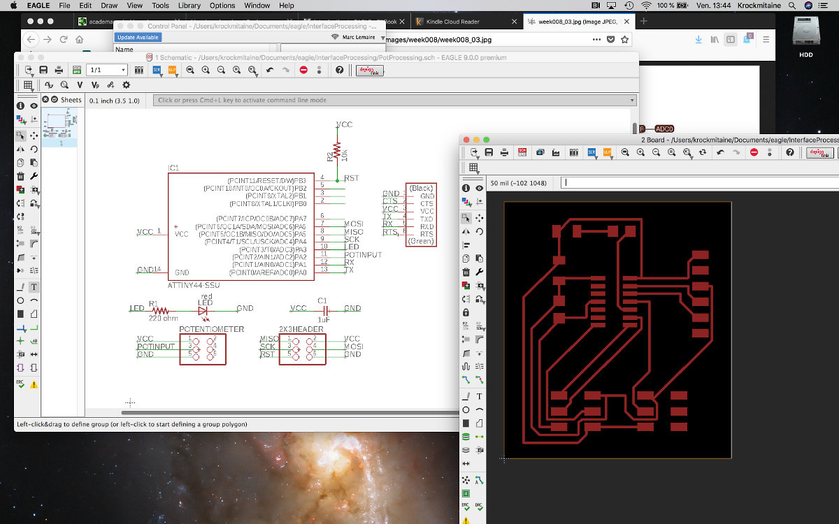
Trying to find an easy, working solution took some though but eventually, as problems piled up, it became so difficult that I had no choice but to simplify the program and work out a solution. I started a new board with an ATtiny44 (more pins). I added some components that were missing in the previous design that might be necessary. Especially noteworthy is the addition of the rx and tx channels connection to the FTDI, a led to see if the board is powered, a 10k ohms resistor and one capacitor. I hope that I cover all bases.
Some kind of unusefullnes: tutorials that don't work
While trying to understand what's going on, I looked into online tutorials, but some are not useful as others. For exemple, this one, made by Sparkfun, seems promissing. Well described, with references, separate page explaining wires and wiring, and the serial communication, I felt like it was a good start. As per my habit, I type the code instead of copy/paste. With this approach, you get the feeling of writing code, making mistakes and correcting them. It's a first step toward at least getting the vocabulary right. So I wrote all the code up to the chapter From Processing.... Instead of having the expected output, all I received was null from the console. Double checking the code to make sure that it's not me, I couldn't find any errors. I then copy/paste the code and to my surprise, the pasted code behaved in exactly the same manner as the code that I typed. I must go elsewhere.
Always remember that YouTube is your friend
Even though I managed to get the output of the serial console to be read by Processing and display the data on the screen, I'm still having lots of difficulties translating from one chip (Arduino) to the other (ATtiny45/44). For starters, Serial.begin, is not accepted by the ATtiny45 (Not declared in this scope error). I must use the SoftwareSerial library and this translates into it's own subset of problems where I can't find an easy solution except diving deeper into documentation, looking for clues.
At last, I went to youtube, looking for some train and unicorns. Instead, I found this one. With this, I made a functionning Processing program that connects to the serial Arduino port. What's more, I learned how to select the channel to listen to under Mac OS X (counting from 0 until the selected port in the Tool>Ports section). The other tutorials that I read make it hard by adding code that prints the available usb channels in the arduino console and leave you pretty much to your own devices for guessing the connection between the serial port and the software. Worth your time.
While at it, I also discovered this one, PlaisirArduino, in French. You have to subcribe to the list to obtain the code. It's worth the trouble because they are really amazing, fully described, with lots of functionning exemples.
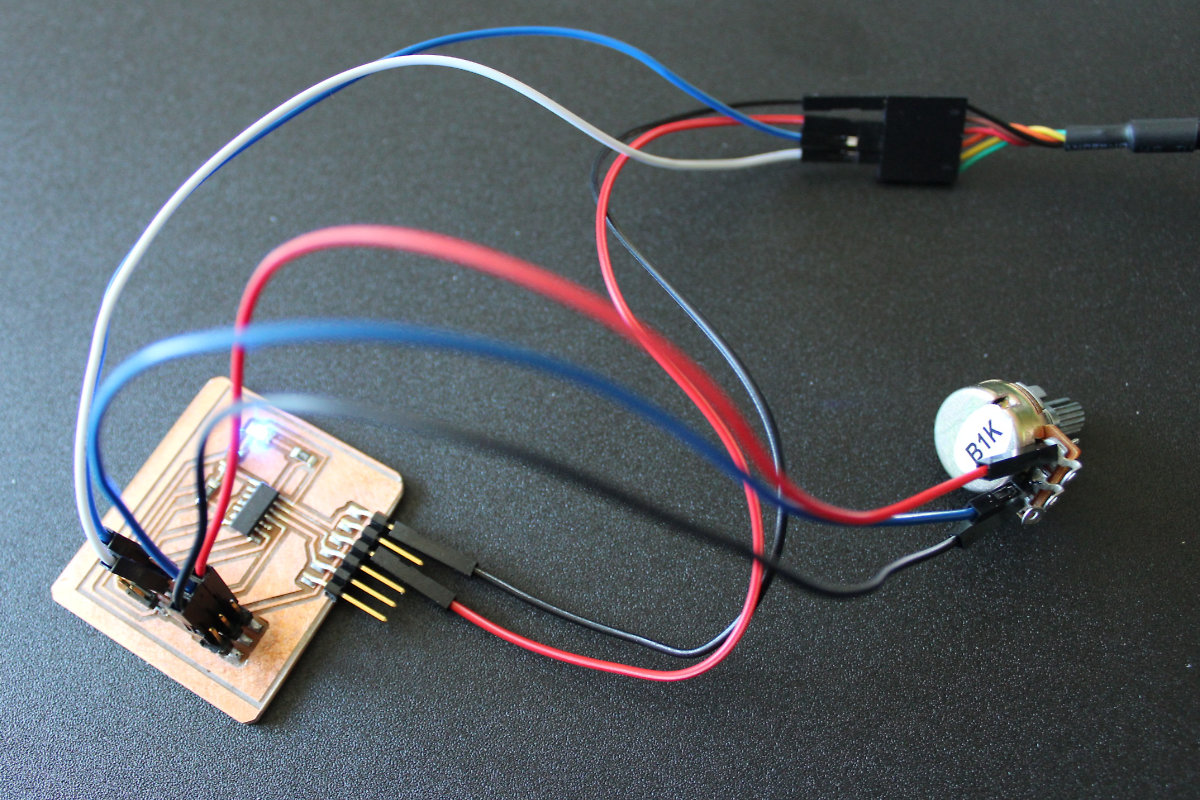
Those tutorials were easy to follow and I rapidly made myself a simple working design that respond to the potentiometer input. Unfortunately, even with a basic code working with an Arduino, I wasn't able to make a succesfull script for the ATtiny44.
The following DAYS were not successfull at locating the problem. And I tried so many solutions that at times I was completely lost with all the arduino test files. At the end of each day, I had to find the original sketch for the next day so as to start with a clean slate.
Eventually, I made a mistake and burned my board. I made a new one, soldered the components and called it a day (last march, this simple phrase meant a one day ordeal, now it's mundane and done in an hour, to give you an idea of how much I've learn since then). This last assignment is turning out to be an unscheduled ordeal.
The path to the solution
I was really near the solution but was too much near the tree (tree? I mean the bark of the tree) to see the forest. I needed some help to solve this problem and François came in to to the rescue helping me find a solution. With a new set of eyes, we quickly separated the problem
First problem we had to fix was a faulty potentiometer connexion. There was a bad solder joint that made the reading of the multimeter goes funky. It was quickly resoldered and the reading were more stable. Later testing proved that this problem was still there but less present. For this execice, it was ok, but for a more rugged application, I should have replace the wire.
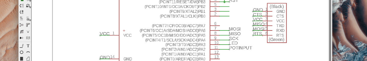
Second problem, related to the human side. When I made the Eagle schematic, I wasn't too sure about the connection that I made between the tx and rx connexion with the FTDI header. I should have asked around as those should have been replaced with MISO/MOSI instead. François made me do the connexion manually with wires and once the board was powered, we had serial output! I immediately knew that we were on our way to fix the problem.

Third problem was the connection between the board and processing: I never took a broader view of my problem and I was using the 2x3 header, used for programming, as the interface for connection! Processing uses the FTDI connector to talk to the computer via the usb port. To determine the correct port, I had to connect the FTDI and look at the port connection and put it down in the script. Once this last step was done, I made the connection and, finally, the program was functionning and this assigment that was done.
This is the final Arduino code:
#include
SoftwareSerial mySerial(5,6);
int potPin = 2;
void setup() {
  mySerial.begin(9600);
}
void loop() {
  int val = map(analogRead(potPin), 0, 1023, 0, 255);
  mySerial.println(val);
  delay(50);
}
import processing.serial.*;
Serial port;
float brightness = 0;
void setup(){
  size(500, 500);
  port = new Serial(this, "/dev/cu.usbserial-A105QHIX", 9600);
  port.bufferUntil('\n');
}
void draw(){
  background(0, 0, brightness);
}
void serialEvent (Serial port){
  brightness = float(port.readStringUntil('\n'));
}Finally, I corrected my Eagle schematic and board and those are included here in the download section.
Final thoughts
This one was really a though assignment. At times, it made me depressed and not sure that I was about to complete the program. The first idea to make something fun gave way to something simple but I learned quite a lot from such a simple square that changes colors. At the start, I had a limited amount of expertise in the field of electronics that explains the creation of so many problems. Now I can say that with this assignment, I've learn a lot about microprocessors and their connections. Those essentials were learned the hard way and won't be forgotten soon.
