Output Devices
Week 12
This assigment is very important to me as I will start to grasp the concepts on controlling stepper motors. Stepper motors are essentials to master as we need to add mouvements and functionnality to our projects. In the first step, I will start with an Arduino tutorial that will show me how to control one stepper motor. Once this is done, I will transfer the program to an ATtiny microchip and make the board.
First, an easy project to grasp the concepts of stepper motors
For this assignment, I've found a really well made tutorial by the team at DroneBot Workshopon the topic at hand that includes links to further deepen my knowledge about motors. It first describe the theory behind stepper motors, how they work, what is stepping and microstepping, define the most common type of stepper motors (unipole and bipolar) and why one is more efficient than the other. This followed by a short description on how to read stepper motor specifications (after reading this, I'm now better at understanding those numbers). It then finishes with a short description of NEMA motor sizes.
They also made a distinction between stepper motors, which are "unaware" of their position and servo motors, which move to a precise angle. Stepper can be moved to an exact position but can become misaligned if an external force is applied to the shaft. As my project involves precision motor, this is something to ponder and probably need further research.
The experiment
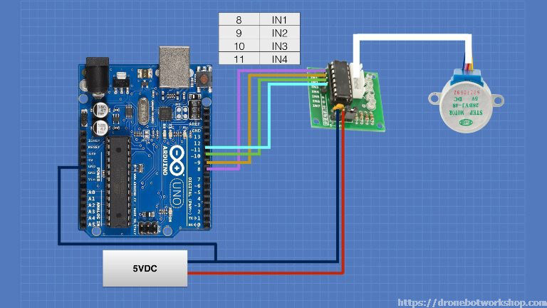
For this experiment, I have everthing that I need. At Benny Fab, I picked up the Arduino board, the ULN2003 Darlington Transitor Array and the 28BYL-48 5 wire unipolar stepper motor that moves 32 steps per rotation with a gearing system that moves the shaft by a factor of 64. It's important to remember that as these numbers will be used in the program. It's also important that the power supply to the motor(s) must be separate from the one that feeds the Arduino board, even though this one is the same voltage as the motor (5 volt), as the electrical noise generated by the motor could damage the Arduino.
The Code
Everything is included in the code. The library is already included in the Arduino IDE. I must add that this code is really well made and documented.
/*
  Stepper Motor Demonstration 1
  Stepper-Demo1.ino
  Demonstrates 28BYJ-48 Unipolar Stepper with ULN2003 Driver
  Uses Arduino Stepper Library

  DroneBot Workshop 2018
  https://dronebotworkshop.com
*/

//Include the Arduino Stepper Library
#include

// Define Constants

// Number of steps per internal motor revolution
const float STEPS_PER_REV = 32;

//  Amount of Gear Reduction
const float GEAR_RED = 64;

// Number of steps per geared output rotation
const float STEPS_PER_OUT_REV = STEPS_PER_REV * GEAR_RED;

// Define Variables

// Number of Steps Required
int StepsRequired;

// Create Instance of Stepper Class
// Specify Pins used for motor coils
// The pins used are 8,9,10,11
// Connected to ULN2003 Motor Driver In1, In2, In3, In4
// Pins entered in sequence 1-3-2-4 for proper step sequencing

Stepper steppermotor(STEPS_PER_REV, 8, 10, 9, 11);

void setup()
{
// Nothing  (Stepper Library sets pins as outputs)
}

void loop()
{
  // Slow - 4-step CW sequence to observe lights on driver board
  steppermotor.setSpeed(1);
  StepsRequired  =  4;
  steppermotor.step(StepsRequired);
  delay(2000);

   // Rotate CW 1/2 turn slowly
  StepsRequired  =  STEPS_PER_OUT_REV / 2;
  steppermotor.setSpeed(100);
  steppermotor.step(StepsRequired);
  delay(1000);

  // Rotate CCW 1/2 turn quickly
  StepsRequired  =  - STEPS_PER_OUT_REV / 2;
  steppermotor.setSpeed(700);
  steppermotor.step(StepsRequired);
  delay(2000);

}
Success!
Now we have the software controling the hardware. It's now time to translate them all into a ATtiny44. I first though that I had to implement the motor driver to the schematic but Mathieu told me that I only need to make the microcontroller board that will connect to the driver. Also, he recommended that I search the web just in case that I need an external clock and if the is some problem loading the stepper.h library into the ATtiny. On both counts I came up empty handed. I added the clock as insurance against troubles. As for the library, since there is no threads related to the stepper.h library, I can take for granted that there will be no problem with my program.
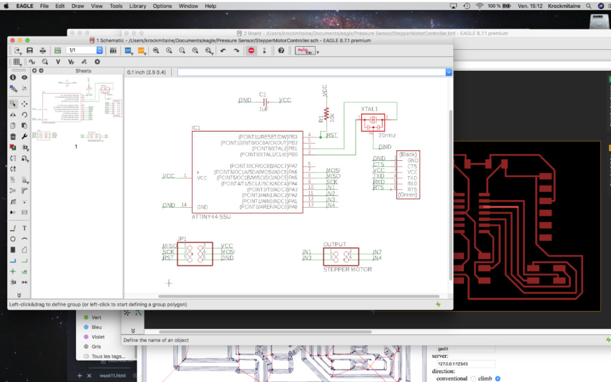
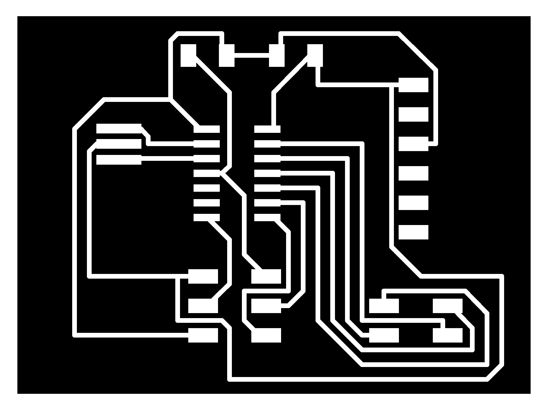
Eagle
Transfering the setup in Eagle was straigforward. I only needed the ATtiny44, the FTDI jack, a 2x3 input for the programmer and a 2x4 ouput for the motor. After asking for a second opinion from Mathieu, I added a 10k resistor connecting the reset to the VCC, a 1uF capacitor from the ground to VCC to stabilize the current and a 20Mhz external clock to make sure that the timing is acurate. The board came out nice on first try.
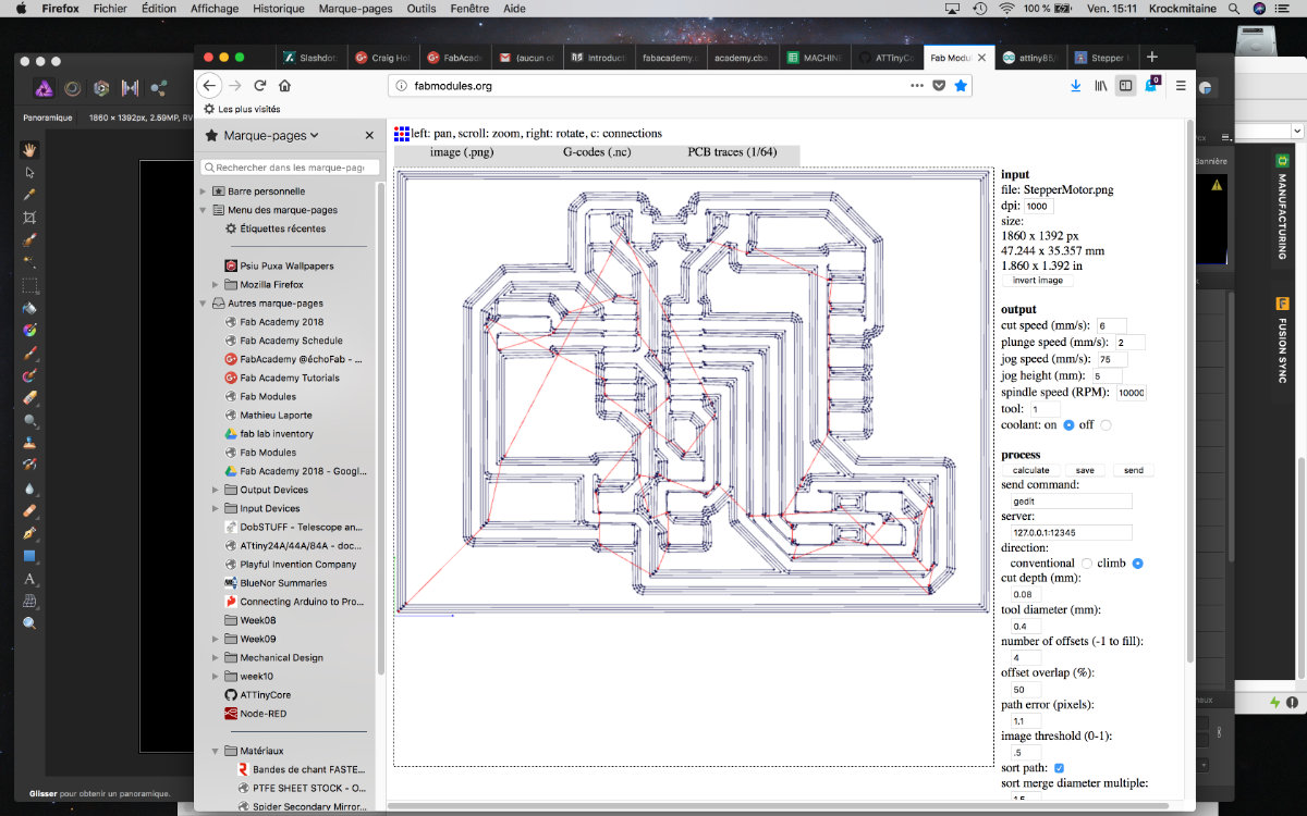
As per my new habit, I change the dpi to 1000, the depth to .08 and the cut speed to 6mm/sec
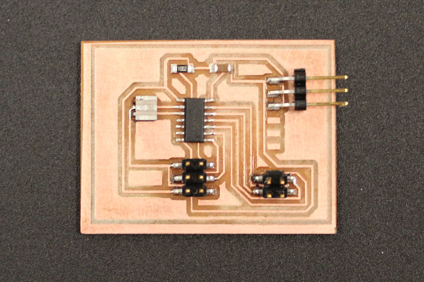
Machining
I spent more time cleaning and setting up the milling machine than the actual milling. The mill was ruined by the previous project had to change it. I had a small copper board that was ready and since the dimensions of the board is small, about 2" by 1.3", I thought that I was ok but the machine milled the traces outside of the board. After a quick search, I found a 2 sided board. I put the whole board on the deck of the machine, made another setup and started to mill. The board came out perfect and is the most beautiful one I ever made!
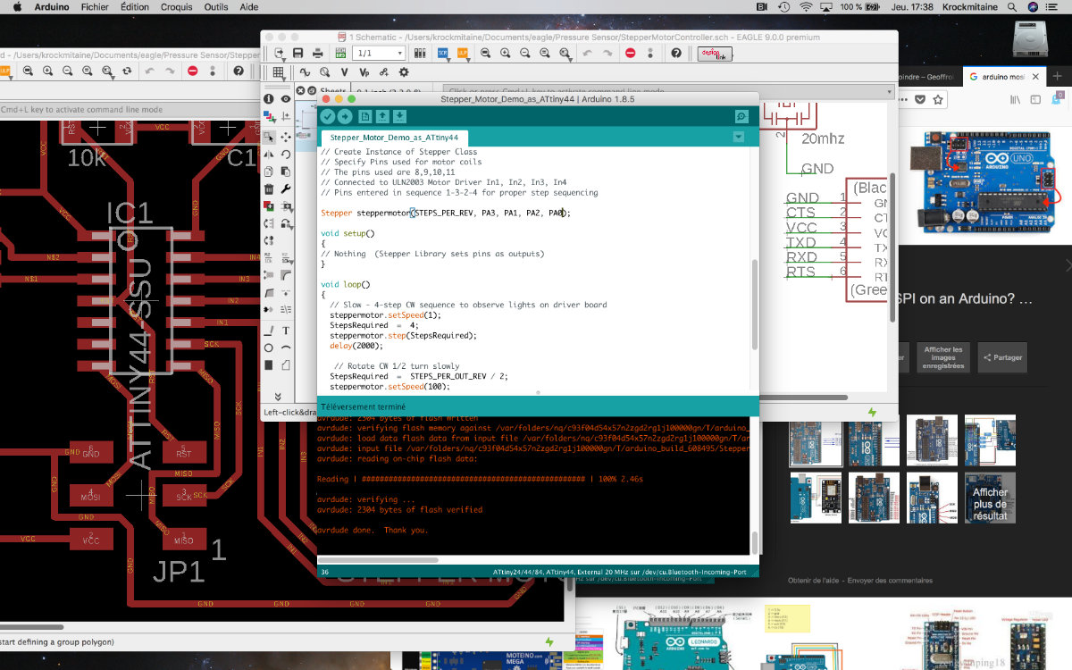
Transfering the Arduino sketch to ATtiny sketch
Since the sketch is quite simple, it was a matter of transfering the pin numbers controling the motors (8, 9, 10, 11) to the ATtiny (PA3, PA1, PA2, PA0). Because there is no special libraries to upload, the sketch was essentially done.
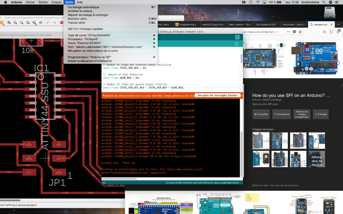
However, a few surprises were waiting for me. I first tried to upload the sketch by using the Arduino As ISP. Having acquired quite an experience with this chip during the input device assingment, before powering the board I checked every single connection. I connected the device and checked if the chip was receiving power (it was). So, while everything was green on my side, I still received the "not in sync" error message. I pondered this surprising message for a while, then decide on another approach: connection via my FabISP.
I made the connection and uploaded the sketch: it uploaded to the ATtiny! But there was motor mouvement. This was another puzzlement. Then I had to answer the door to the lab and came back and there it was: the leds on the drivers were lighted and although slowly, were making the sequence of the original sketch! The motor was turning slooowwwww, really really slow. I had to held it in my hand to feel some vibrations, and heat, to convince myself that the stepper motor was indeed activated. I changed the speed parameter of the sketch and I could see that the motor was moving.
Needless to say, I was ecstatic. Here's a video of it with my FabISP.
