The Ground Board
Evolution of an idea
Before realising the final project, I must first master how to draw with parametric design software, namely Fusion 360. I had previous experience with CAD design. Compared to today's offering, it was really primitive as we had to design every part and then make the final assembly plan. Fusion 360 on my old Mac is way more powerful than the big station that I used back then.
First design of the Ground Board
Fusion 360
It's been decades since I touched a real CAD program and this one is a complete change of what I'm used to. I immediately saw the big advantage of parametric design. In the Highe book, the author includes an excel sheet for different telescope diameter. Instead of going back to consult the excel sheets and redo the plans, I draw once and modify the dimensions to suits personnal needs.
At first I was having some difficulty working with Fusion 360, namely with the concepts of sketches, but I went back to Lars Christensen's absolute beginners tutorials and re-learned the lesson that a sketch must start on a surface or a plane.
First attempts at the Ground Board
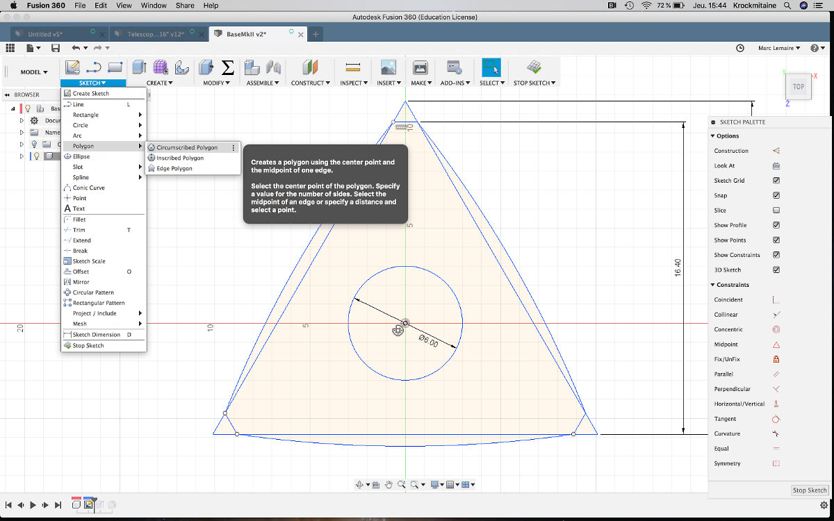
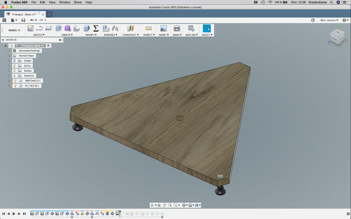
My first attempt was designing the triangular base. It's a simple shape, ideal as a stepping stone into learning Fusion. Making the triangular-shaped ground base was difficult at first, as I was trying to draw each side of the triangular base on the XY plane axis. I had a few basic dimensions from the book but those weren't refering from a center point: I had to compute everything by hand. It was complex and not fluid workflow and wasn't really happy with the results. So I started anew, using construction line from the center point and it came out more smoothly.
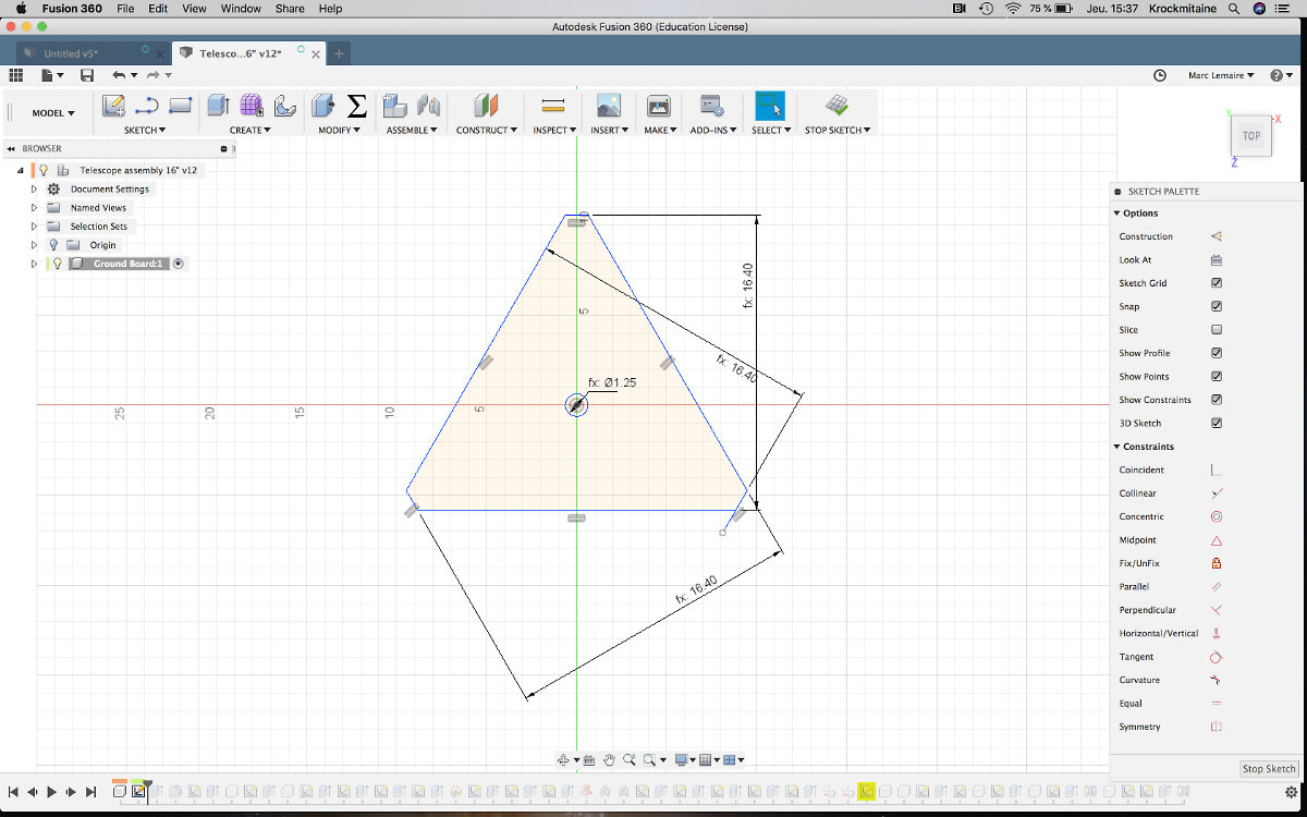
I found the solution by accident: under Sketch, Polygon, youu have three choices to create a polygon. I chose Circumscribed Polygon, entered a measurement, then the number of sides (3) and voilà, a centered triangle.
Following this discovery, I made further progress and completed the design of the ground board.
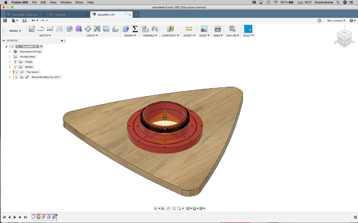
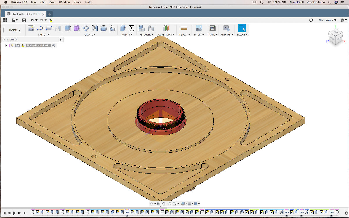
The connection between the ground board and the rocker base is made via a simple dowel pin. I had some misgivings about this pivot point. I have to develop a motor and gear system that will control the rotation of the rocker base. If I add a gear system too near the central axis, I will need a more powerfull motor.
A case of serendipity
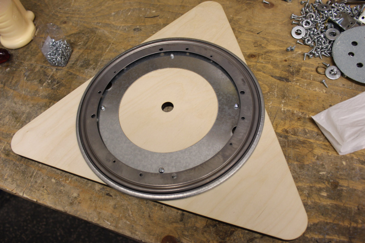
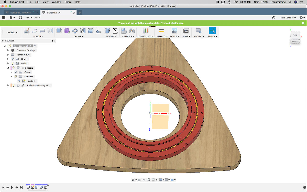
I was pondering those ideas as I came across a Lazy Susan that my instructor ordered for a project of his own. I kept looking at it, founding this part really interesting. I felt that it could be of use for my final project and use it as an interface between the Ground Base and the first version of the Rocker Box. As there was a big hole, I managed to get the Lazy Susan centered on the Ground Base by engraving the inner diameter to the plywood with the laser cutter. I fixed a central pivot point with a peg and put some gears that made the parts rotate. But I started to wonder why not get rid of the central peg by making a central hole the same diameter as the one on the Lazy Susan. Then I asked myself why not get rid of the Lazy Susan, an expensive item, by making my own bearing? Next, why not put the gear on top of the bearing so I'll get vertical weight support and motor rotation via the bearing, simplifying the motor interface at the same time? I knew I was onto something. I ordered one and started to design the connection between the Ground Board and the Rocker Base.
The birth of the MkII design
The problem with the Lasy Susan was the larger diameter than the ground board. The design had a strange look with the center hole still in place. I realised that the center hole was now useless, replaced in it's function by the Lasy Susan. If I increase the hole to the same inside diameter I would shave off some weight...
Then it hit me. The author has an approach to telescope building that simply don't apply to me. His DIY approach is very good when using traditionnal tools but within a FabLab ecosystem, more options are available. So I added some curves to include the diameter of the Lasy Susan and suddenly, I realised that I was creating a whole new design of my own for the ground board and I will have to modify my project accordingly.
The next idea came one night: geting rid of the Lazy Susan. When I decided to use the Lazy Suzan, I was in a rush to find a solution to the problem at hand: make a rotating base. But I came to the realisation that there's two things that I don't like about it: weight and price. As this item is made of steel, I get a weight increase that I don't like. On the other hand, making a 3D print of the bearing in plastic, I will get the benefit of lightness via the material. Another plus is that I can carve out big central hole in the ground board and reduce weight of the assembly at the same time. This would be an advantage. Also, the Lazy Susan is store bought with a price tag of $25.00CAD, so getting rid of it would decrease the total price of the Ground Board assembly.
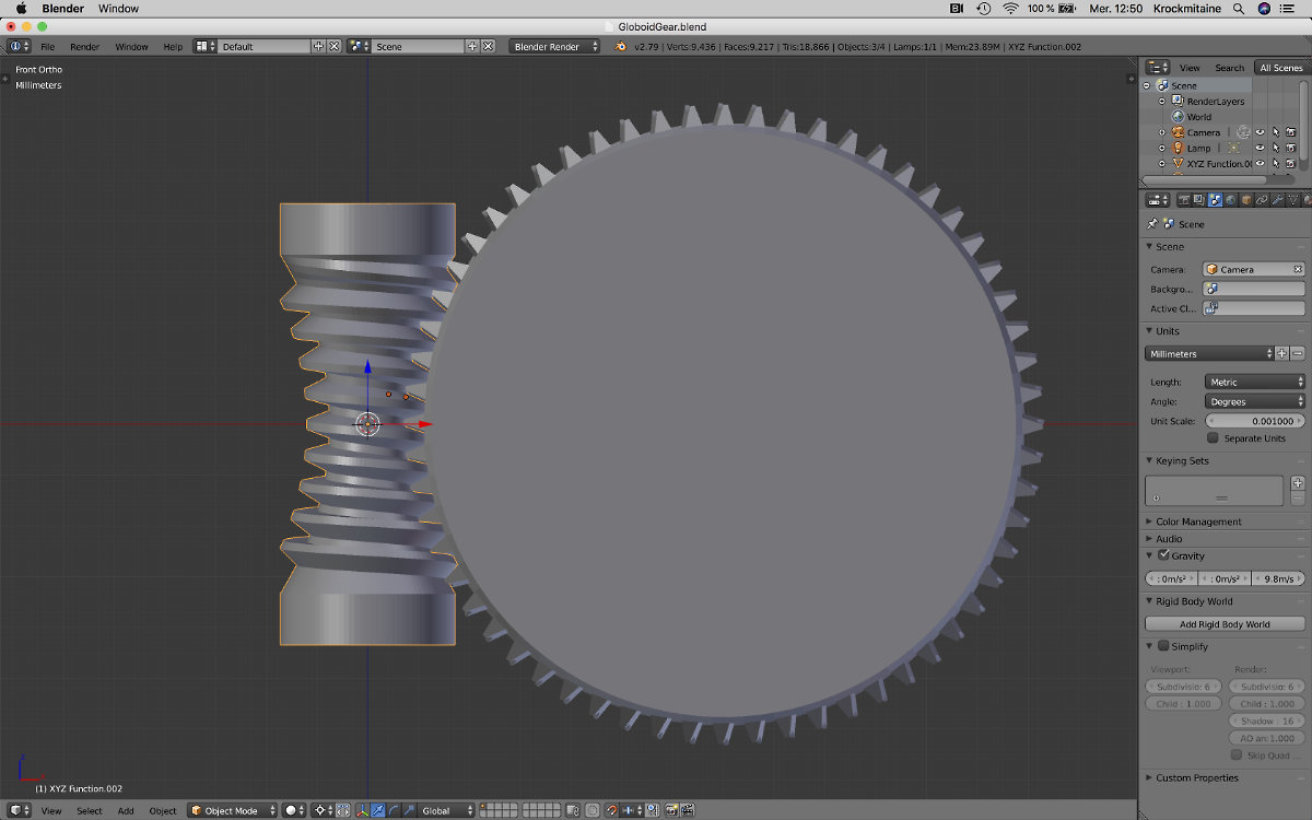
I knew about a project in Thingiverse about making your very own parametric customized slew bearing. Why not using this project as a starting point for supporting the base and telescope assembly and add a gear tower on the top for the future driving mechanism for the rotating base? Using this route, I gain a weight advantage. Plus, I have a customized 3D printed bearing that cost next to nothing. Notice that I'm back to my original idea of having a Globoid Gear as driving mechanism!
The Making of the Slew Bearing
Now's the time to design the replacement for the Lasy Susan. As explained earlier, besides being heavy, the Lasy Suzan is a costly item. It would benefit the project if this item could be replaced by a cheaper alternative. As it happened, the source of my inspiration is a Thingiverse project in the form of a slew bearing. The author made a very nice tutorial on how to make a parametric slew bearing design in Fusion 360. I followed along the tutorial, and made a first design.
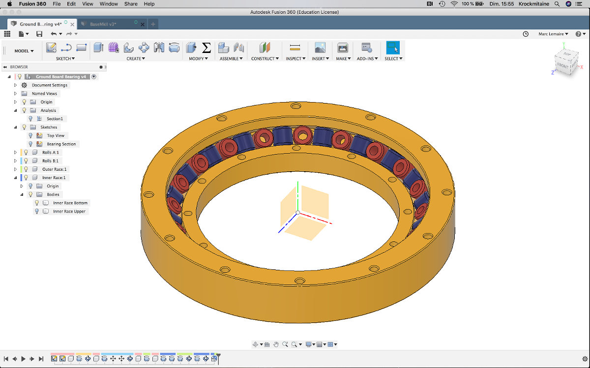
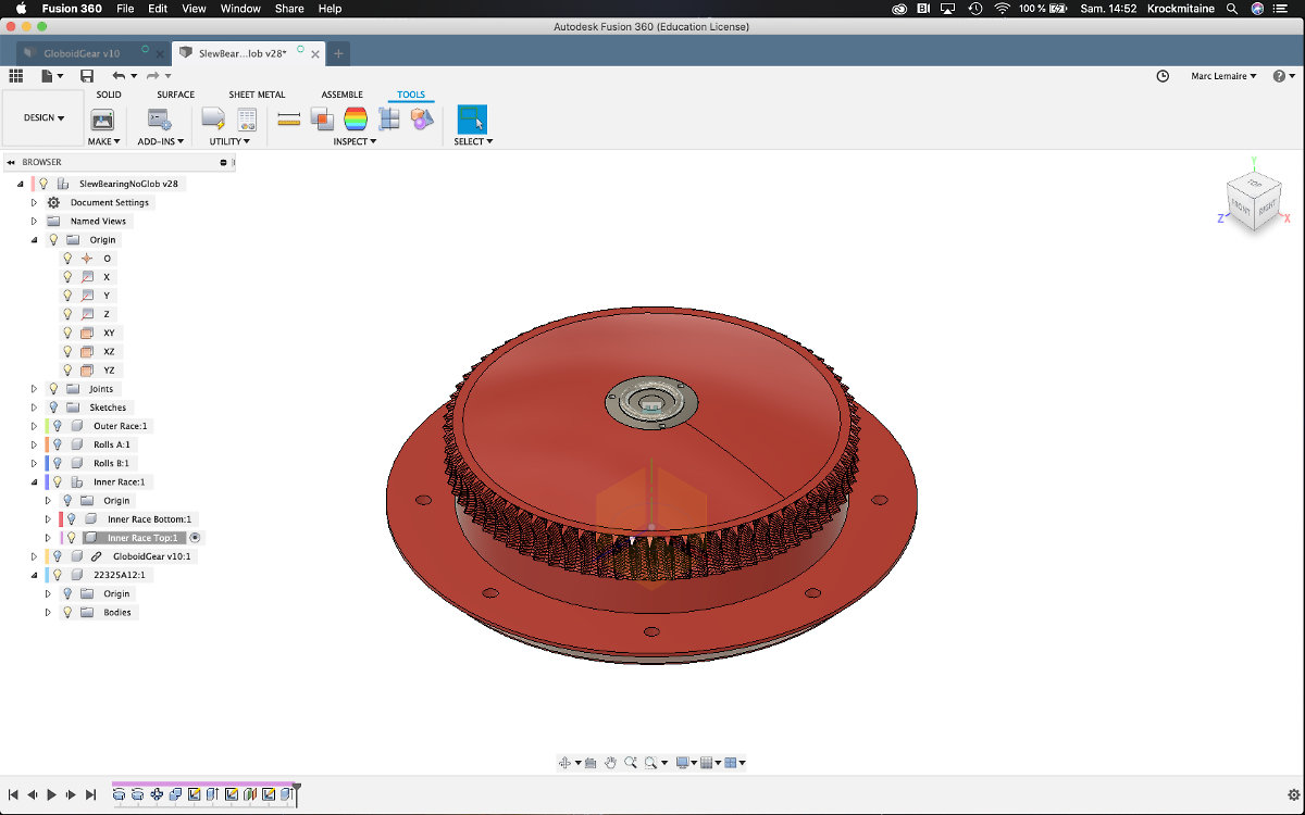
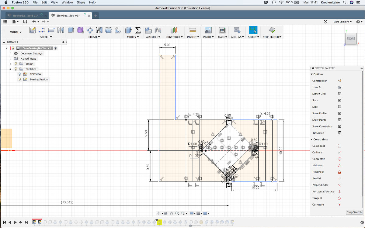
I gained a new expertise at designing slew bearings. Now I need to integrate the globoid gear into the slew bearing and add this part between the ground board and rocker base. Before going further, I must sketch on paper what I want to do, adding a few basic dimensions. I know that the center hole has a diameter of 6 inches, so a radius of 3 inches, or 76.2 mm. Since the rest of my desing will be in metric, I will use 75 mm for the central hole in my Ground Board.
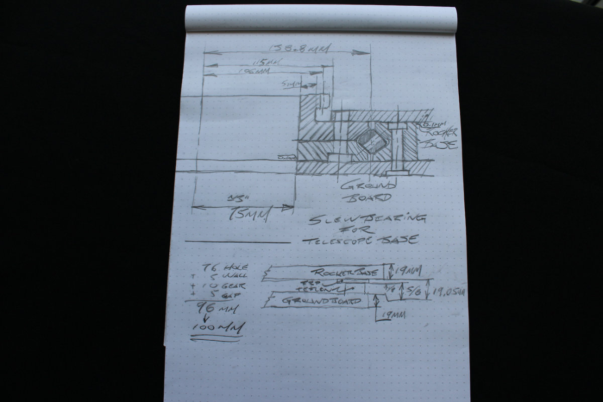
I have to integrate the globoid gear on top of a cylinder using the Top Inner Race as base. For the slew bearing, I will increase the number of rollers from the tutorial to 72. The inner race will be connected to the Rocker Base and the outer race will be connected the Ground Board. Here's the sketch to get a grasp of my design. The author noted some desing problem with his design so mine will integrate tighter tolerance and an offset between the inner and outer race to let the slew bearing freely rotate.
I must confess that I still have a lot to learn before I consider myself an expert in Fusion. When I started this tutorial, I though that it would be easy to modify the file to suit my needs. Not so. I noticed that when I changed my file, everything else changes also. There's too many constraints that were interconnected and it wasn't useful for my case: I had to redo everything while being careful with the design of the inner and outer races of the bearing.
I started anew with a good idea of what I wanted to do. I created my sketch profile and slowly made my desing. With my sketch, I created a preliminary profile for the slew bearing. I increased the size of the rollers from 8mm to 12mm. The required height of the bearing was calculated to be 5/8" for the Teflon pads plus the ⅛" FRP plastic sheet, so ¾" or 19mm. I increased the size of the Ground Board Hole so that it falls within the space between the inner and outer race. Let's get drawing!
Some designs flaws...
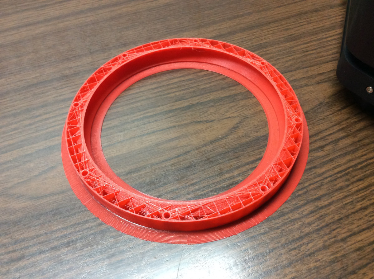
So I went ahead and made my design with my drawing as a guide. Everything went according to plan and I finally made the slew bearing to my taste. Out of curiosity, I put the bearing on the top of the Ground Board to see what it looked like. It wasn't obvious because I was designing for a bearing as large as possible to be put on the Ground Board but it eventually dawned on me that the bearing was too large to be printed on the printer! I designed the bearing by considering the largest possible radius for the gear without taking into account the extra dimensions needed for the Outer Race of the Slew Bearing.
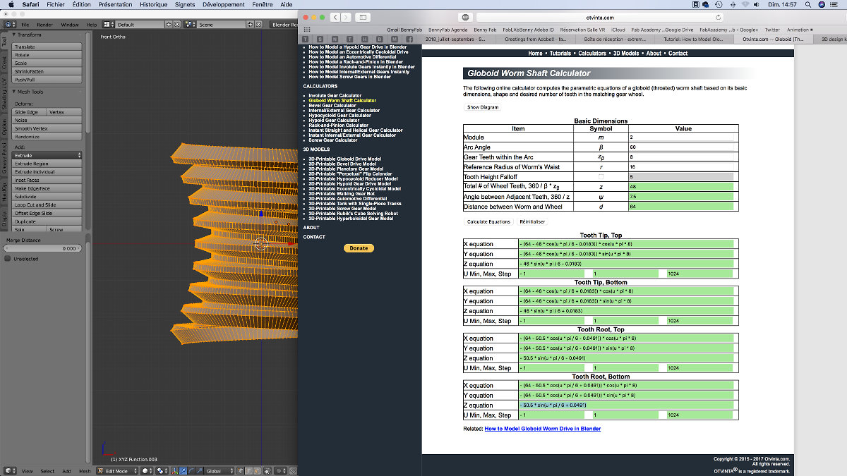
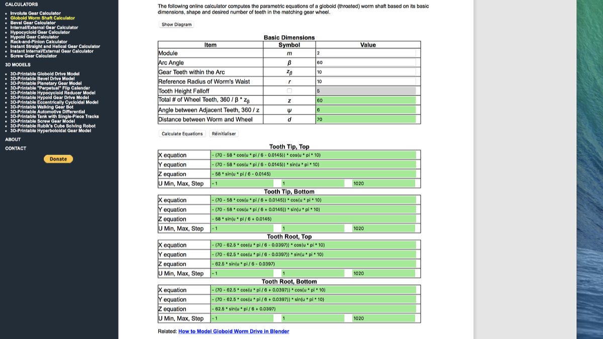
Since I had to start anew, I had to be carefull and not make any mistakes: I had to desing a gear system/bearing package that has a 100mm radius footprint, well within my printer's range. Since I know about how to make a Globoid Worm Gear, it was time to take care of the Globoid Gear. I went back to the Otvinta.com website and put new number to create the appropriate design. Then the last one, nagging problem with the calculator hit me in the face when I completed the worm: I was using the the number Distance between Worm and Wheel as my interaxial distance: it is not! I must substract Reference Radius of Worm's Waist FROM Distance between Worm and Wheel to get my interaxial distance!
Getting it right, at last.
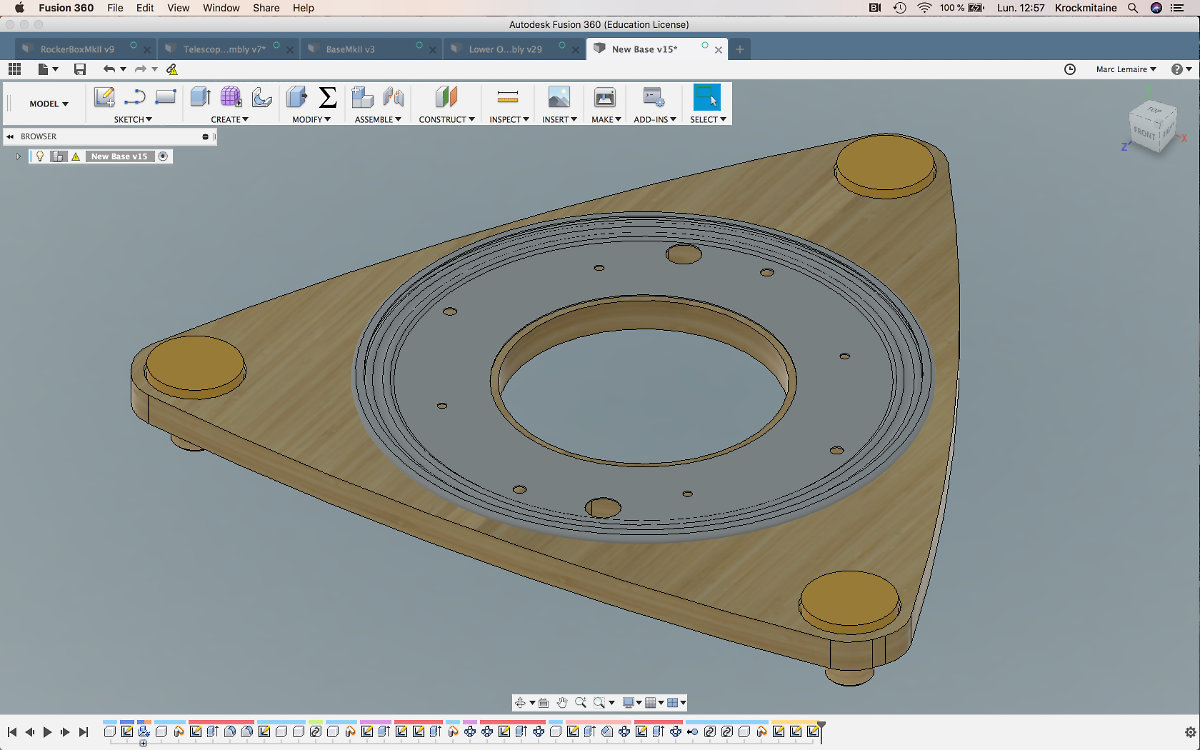
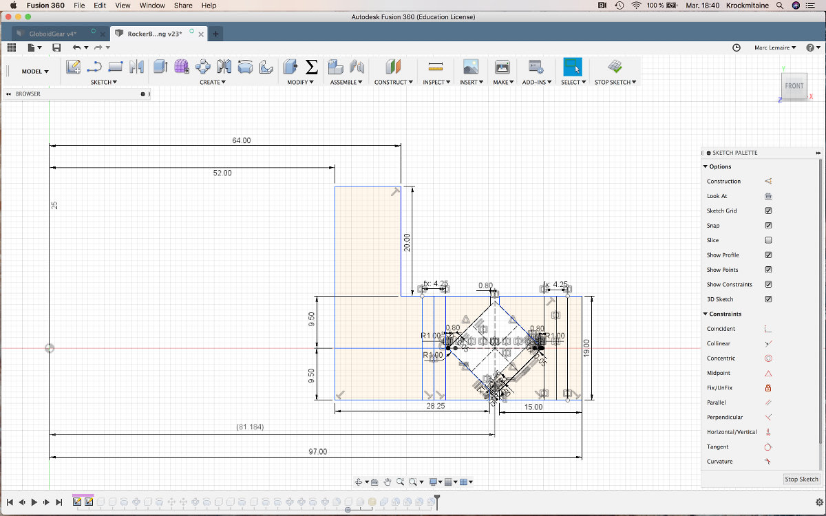
In order to get it right, I need to start from the exterior of the bearing. I gave the outer race a width of 15mm, a gap distance of 1.6mm between the outer and inner races, and a width of 28.25mm for the inner race. The inside diameter of the slew bearing is 104mm and the outside diameter is 194mm. For the design of the gear, I wanted a distance of about 60mm from the center so I came up with a module of 2, an arc angle of 60°, a gear teeth within the arc of 10. For the worm gear, I want a radius of 10mm. All these parameters gives me a total interaxial distance of 70mm, which satisfies all conditions. I also increased the diameter of the central hole on the Ground Board to 162.3mm to eliminate any possibility of rubbing of the Inner Race against the Ground Board.
I will not describe the making of the gear as I followed the tutorial. I eventually complete it and made some side extrusion and closed it with a face for a watertight mesh and exported the stl file.

It was now time to transfer the file from Blender to Fusion. I knew from previous experience that this is a tedious task full of trappings. First, uploading the file directly will involve a scale up of the dimensions and true to previous experiences, it scaled up. I turned to Youtube to see Lars Christensen's video about working with stl files. But under the suggestions, there was also another tutorial on how to work with stl files in Fusion. Instead of using upload, I used Insert Mesh under the Insert tab and there won't be any scaling issues.
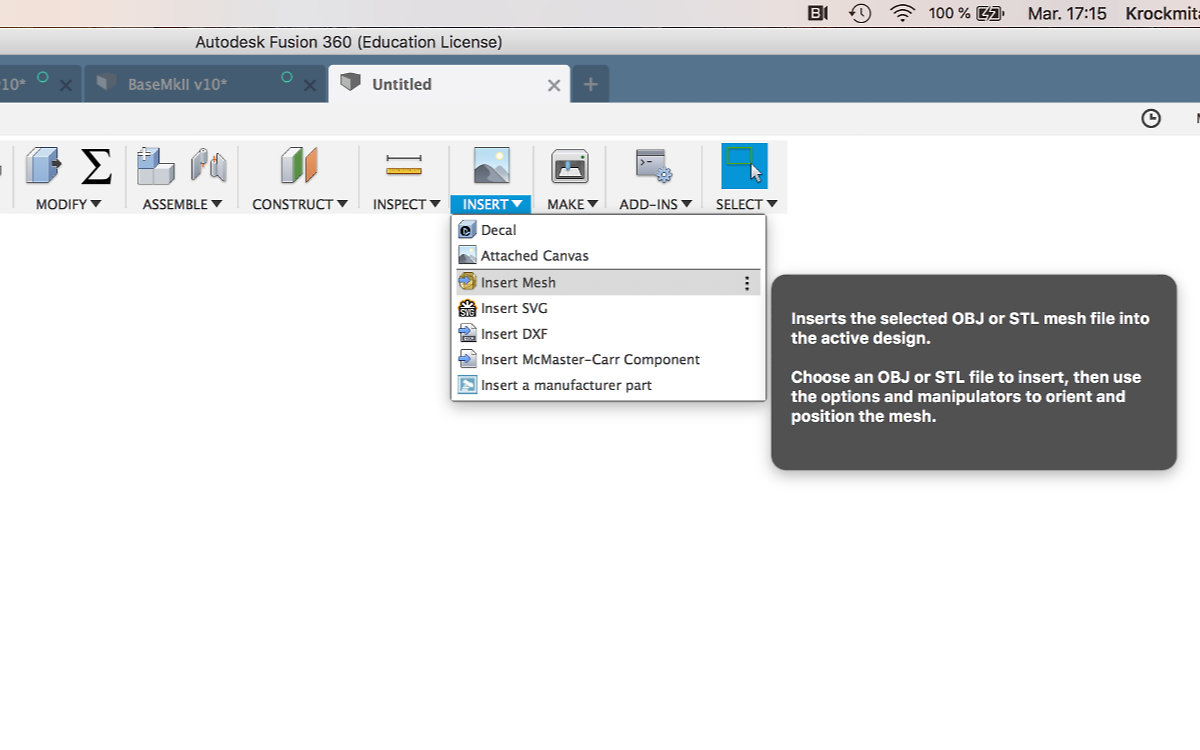

But inserting the mesh is half a victory: Blender exports stl files with triangles (as all stl files), but Fusion uses quads to make a mesh, a nice cocktail for problems.

Next step is to add this mesh to the Top Inner Race. After many failed attemps, I finally found the correct workflow: inside the gear file, I extruded an inside diameter hole of 104mm. I putted a cylindrical form on top of the cylinder, mirrored it then made a cut from the Modify - Combine selection. Once this was cleaned, I inserted the desing into the Slew Bearing project.
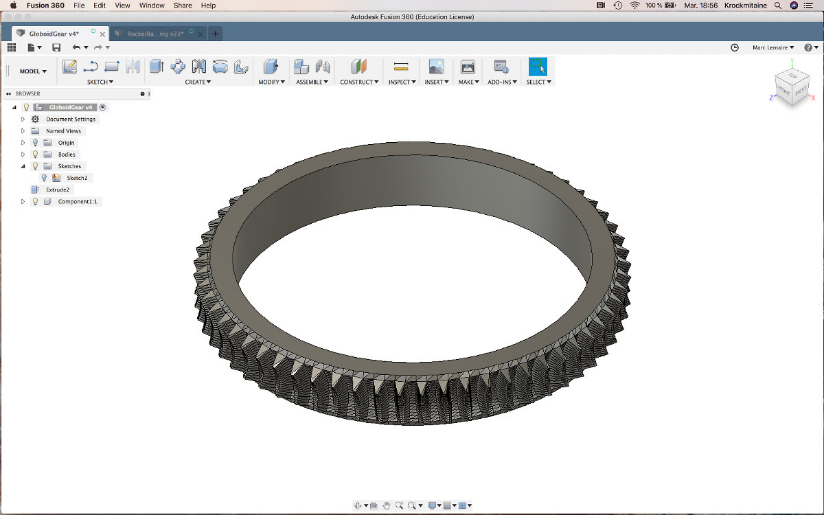
At last I was able to see the complete slew bearing with the globoid gear on top. I'm not entirely satisfied because there the triangles artifacts from the stl transfer. I have to correct this within Fusion but this will no doubt involves a lot of patience to do both the worm and gear. In any case, beyond these æsthetic considerations, this parts will cost next to nothing compared to sending it to a machine shop. By itself, custom ordering this part would cost the entire telescope assembly.

Now's the time to get busy and do the Globoid worm gear. Since this an almost repeat of the previous design, this one went well.

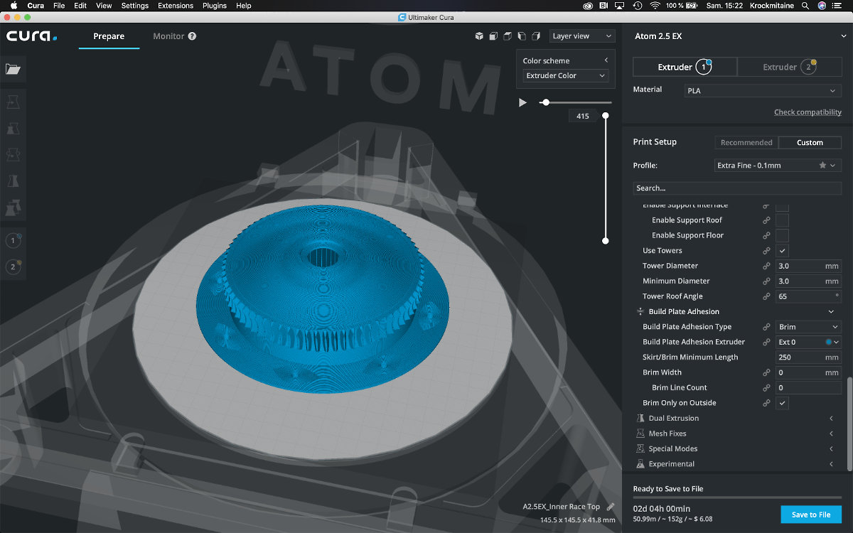
All looks fine but there is still the problem of printing the bearing: even though I was carefull not to reach to the maximum radius that the machine can do, will there be enough place for the outer race to print?
To the printer!

The gray shaded form of the Outer Race indicates that the printer can't take my design by not much. Only solution is to shrink the diameter by a few millimeters so I will be able to make the print. But changing the diameter involves changing all dimensions. I first changed the numbers of rollers from 42 to 38 and got a diameter of about 147mm. After exporting the mesh as stl file, I got the green, or should I say, the yellow light from Cura for this redesign. For the time being, I let go of the globoid gear tower as this is still an experiment and the slew bearing might need some dimensionnal adjustment.

Never forget that danger may come from above
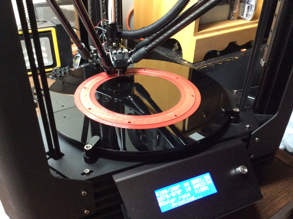
I left the printer doing it's job when I went to mine. The platter is at eye level but the filaments spools are really high, this is a really tall Delta printer. When I came back I saw that at least, no big plastic mess was waiting for me. The machine was quiet and neat. But upon approaching, I saw that I clearly forgot to check to see if I had enough material. I wanted so bad the courses to be red and the bearing black that I never truly checked the available quantity and the reel was empty, the part never completed. I immediately started another one in black that will be ready tomorrow morning. I hope that no further problems will arise.
When Black is the New Black
I went to the machine before I took my Morning Joe and was amazed at what I was seeing. The Outer Race was there, almost done and really neat looking. It took an hour to finish the part and let it cool off before lifting it off the plate. It's a perfect flat piece both top and bottom side. I'm amazed that's my design.
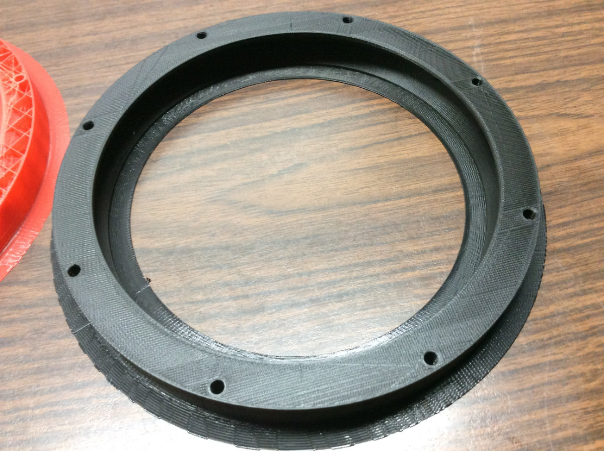
Before leaving, I send to the printer the Bottom Inner Race and the results did not deceived. After cleaning up the parts, I made a preliminary assembly and I'm surprised by the tightness of it all. Once completed, it will be an amazing piece: a 3D printed slew roller bearing made to my needs!
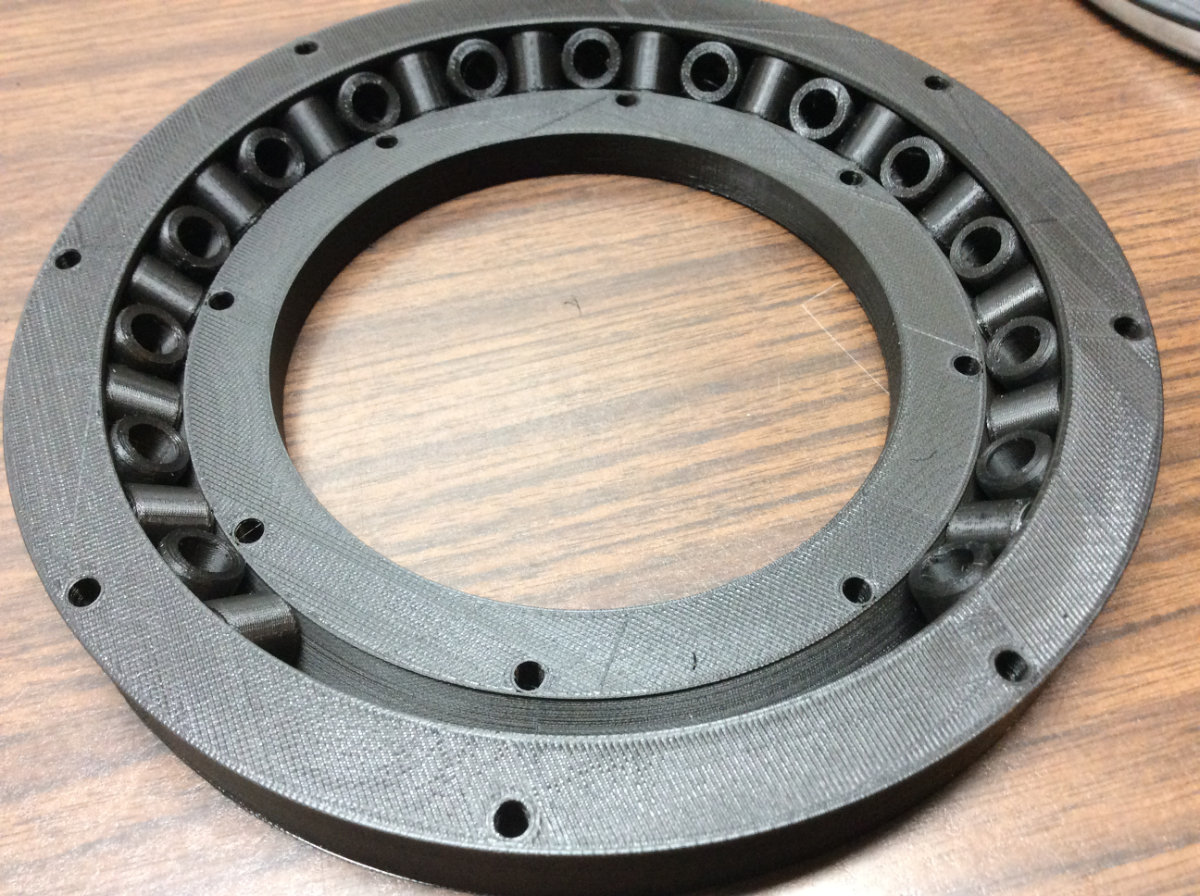
The last parts of the slew bearing were completed during the night and they came out as nice as all the other parts. I only needed to go to the hardware store and buy the appropriate M4x25 screws, bolts and washers. The only task remaining was the assembly, which was easy.
I'm really amazed at the tight tolerance of my bearing; there's no slack, wobble or annoying defect. But I made the rollers in batches of 10 at a time and this shows when I turn the bearing because of the retraction of the hotend when it hop from one bearing to the other, the surfaces are uneven. Next time they will be printed one at a time. All in all, I designed a roller bearing made to my specifications. It is a neat replacement to the Lazy Susan of the first prototype. For the next version, I will include the globoid gear on top, but for now, I enjoy playing with it!

The Struggle of the Crown
As I reflected on what I've done so far, I wasn't happy with the result of the crown gear. There's way too many triangles and I would really like to have a nice surface keeping the triangles for the gears themselves. I found that importing an stl file in Fusion generates tons of triangles that slows down my computer. Trying to find a solution to this problem while searching YouTube made me realised that if I wanted a nice rendition of my design, I had to redo everything. Not good. And the worse is yet to come as I would have to redo this for the worm gear, which is way more complex.
Following this conclusion, a search for a suitable workflow followed in which I first learned that stl might may not be the best of option but obj files might do the job just fine. Indeed, obj creates quads instead of triangles and the file is nicer in Fusion. Eventually, I learned that the quickest way to go from mesh to body in Fusion is to click on Create then Create Base Feature, which enters a direct editing mode and creates an history free timeline. Change the Document settings to metric (mm). Then insert the mesh, I choose to insert an obj Globoid gear, In the options box, I rotated the gear 90°, checked Center and Move to Ground icons then clicked OK. Next is the transformation of the object into a body for editing in Fusion: right click on the object, click on Mesh to BRep that shows on the menu. You click on the box OK and let the CPU do it's thing. Click on Finish Base Feature and I now successfully transformed the obj blender file into a new body in Fusion.
Out of these long hours of experimentation, I nail down the easiest process to transfer the files from Blender to Fusion: the best way to adapt the globoid gear in Fusion was to create the gear in Blender, make a full object without any holes or angles, export it in Fusion, then transform the obj into bmesh as described above so I have a body to work on. From this initial shape, then cut throught the body with another form to smooth the surface and cut down the number of triangles. Easy as pie, I mean, now it is; had to deduce the workflow throught sheer hard work and determination. And I still have to be careful with the process otherwise it don't work.
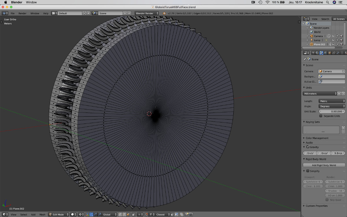
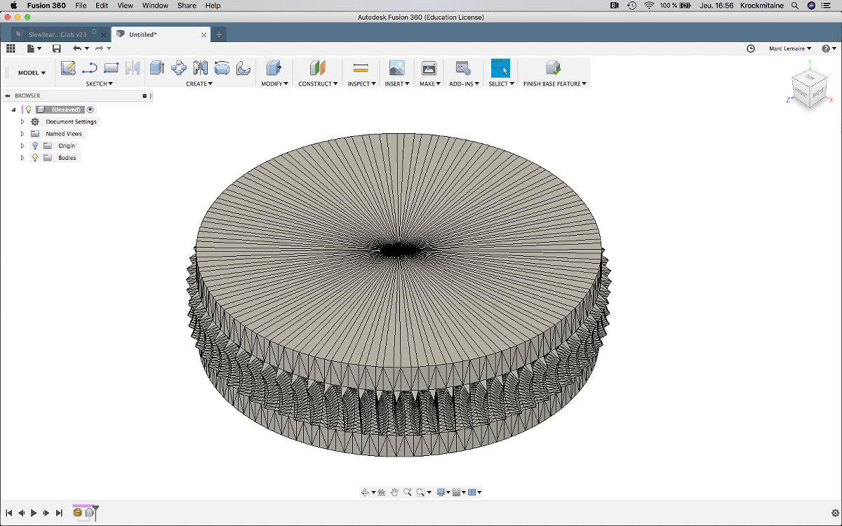
I still have a lot of triangles, but they are located within the gear area as I wished them to be. I edited the body mesh by adding a sketch over the surface of the gear, then extrude down a cylindrical form to the base of the gear profile to define the central hole. I finished the desing by adding a top fillet for a nice finishing touch.
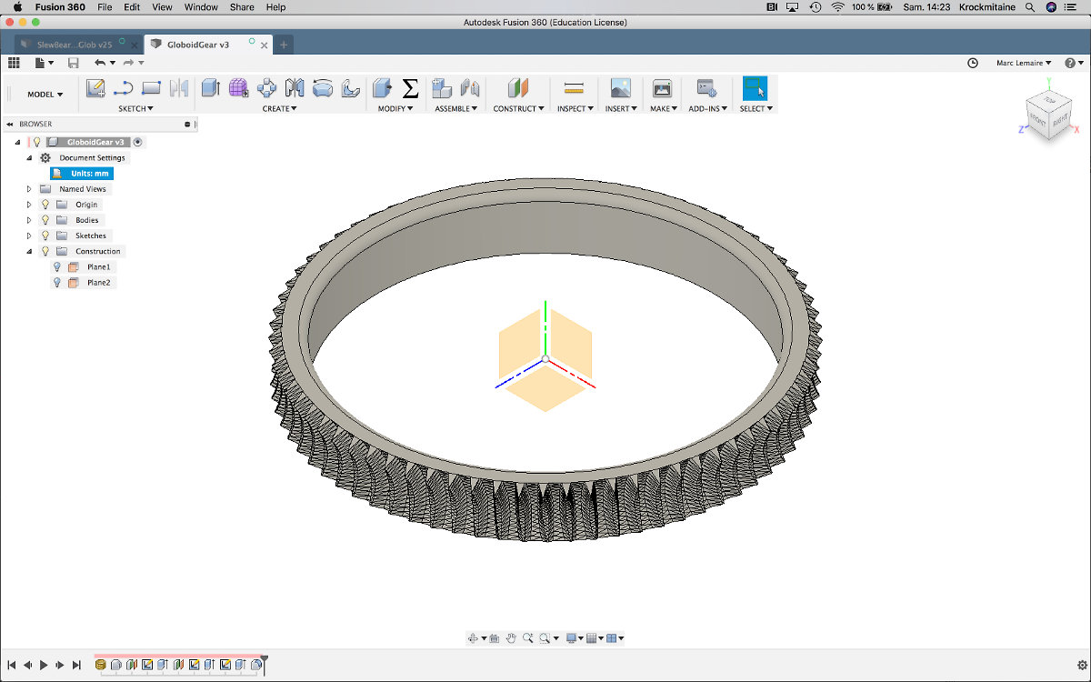
Next, I edited the Top Inner Race sketch to have a clean assembly with the Globoid gear. From the previous test, I had to modify the profile to eliminate any possibility of friction. I thinned the wall down to a little less than 5mm, being forced to reduce the inner diameter down to 98mm, and combined the two parts together. Now, at last, the gear is now flush to the wall and there won't be any friction between the worm and the gear.
After all these endeavors, I guess I finally hit the perfect profile for the slew bearing. Except there is still the vertical dimension to be fixed between the Ground Board, the Rocker Box and the motors assembly. This will comes in the next chapter Rocker Box.
For the next iteration of the slew bearing with the Globoid gear, I made the print to test the look of the profile gears by printing without any support. And for a finishing touch, I printed the roller bearings one by one. This time, all the parts were printed to extra-fine settings (0.06mm).
This print came out more nicely than the first one. The parts are amazing, and the bearings rolls way more smoothly than the first one. As expected, the top of the crown don't show any of the triangles of the original mesh, and the gear profile is amazing. As the gears were so well defined, I decided to print the globoid worm gear that goes with it. The worm gear came out nice for the first half of it but I have a problem with printing on the second half, where the worm gear has a negative horizontal angle. I have to investigate a better way to make the worm gear. And there's a small area where there is friction between the worm and the gear that needs to be fixed for the third prototype.
All in all, the results are conclusive and as expected: the contact between the worm and the crown gear is tight. So much so in fact that I will have to design, on the Rocker Box, a cluch to engage the gears together. Otherwise, a permanent connexion will create problems and maybe damage the driving mechanism. This will be done on the next phase of the design.