NOTE: Vigyan Ashram is known as "Fablab 0" , it is one of the remotest labs with very minimal internet access , therefore, we have been using old version of Fab module which is an offline version.
WEEK 13
Input Devices
Learning Outcomes:
1. Studying Input device
This week i connected IR sensor as my input device and RGB LED back from my output devices on my self designed microcontroller board.
This is related to my final project where whenever IR senses a tool or any object it will turn LED green and otherwise RED.
I read about different input on Fab Academy , went through all the videos mentioned in the input devices.
2. Designing , Fabricating, programming my 3 boards
USING:
Eagle 8.0.1 and Rolland ModellaThis week i made 3 boards:
BOARD 1: Attiny 44 for my output devices and input devices week
BOARD 2:Atmega 328 for my final project, being measured through Grasshoper
BOARD 3: Input Button board being measured by DSO machine
BOARD 1 - Attiny 44:
I went on to eagle and designed my board in output devices week WEEK 10
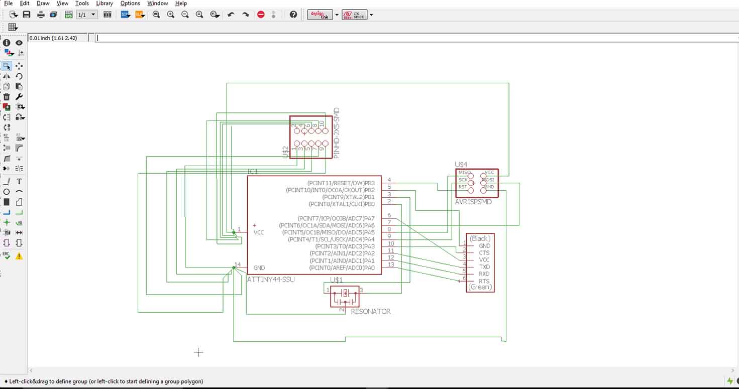
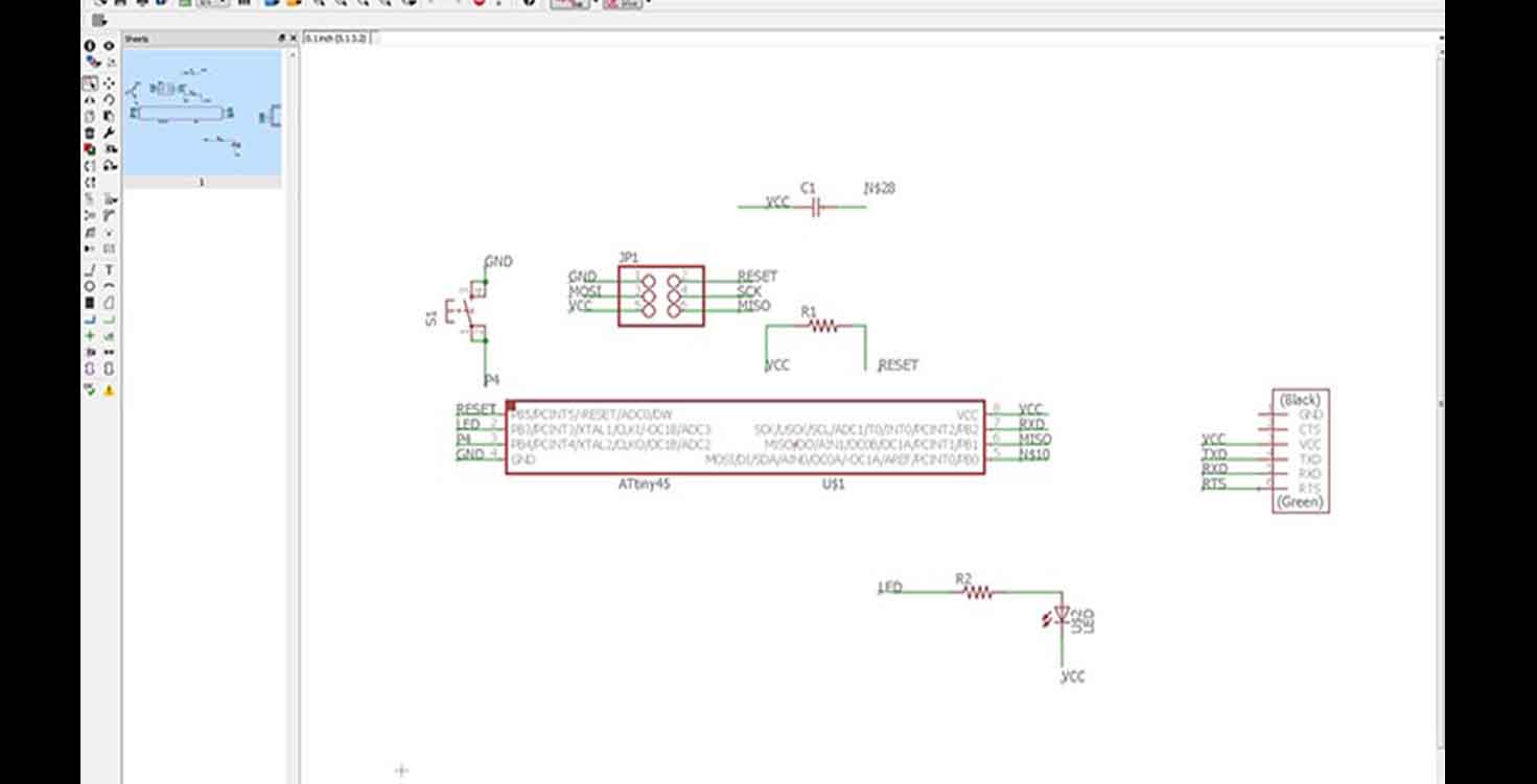
This is my schematic board where i have used Pin header 2x3, Gave one row of GND on left and One whole row for VCC (2x6), Attiny 44 and a resonator.
My board file
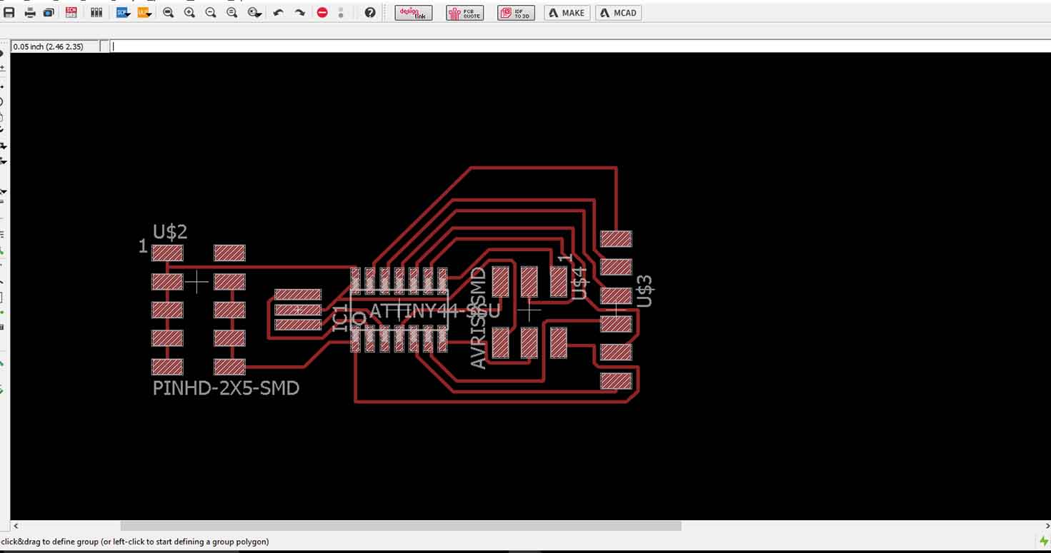
I auto routed my board , you follow steps for the same in Output Devices and got 100 percent routing in 14 variants.
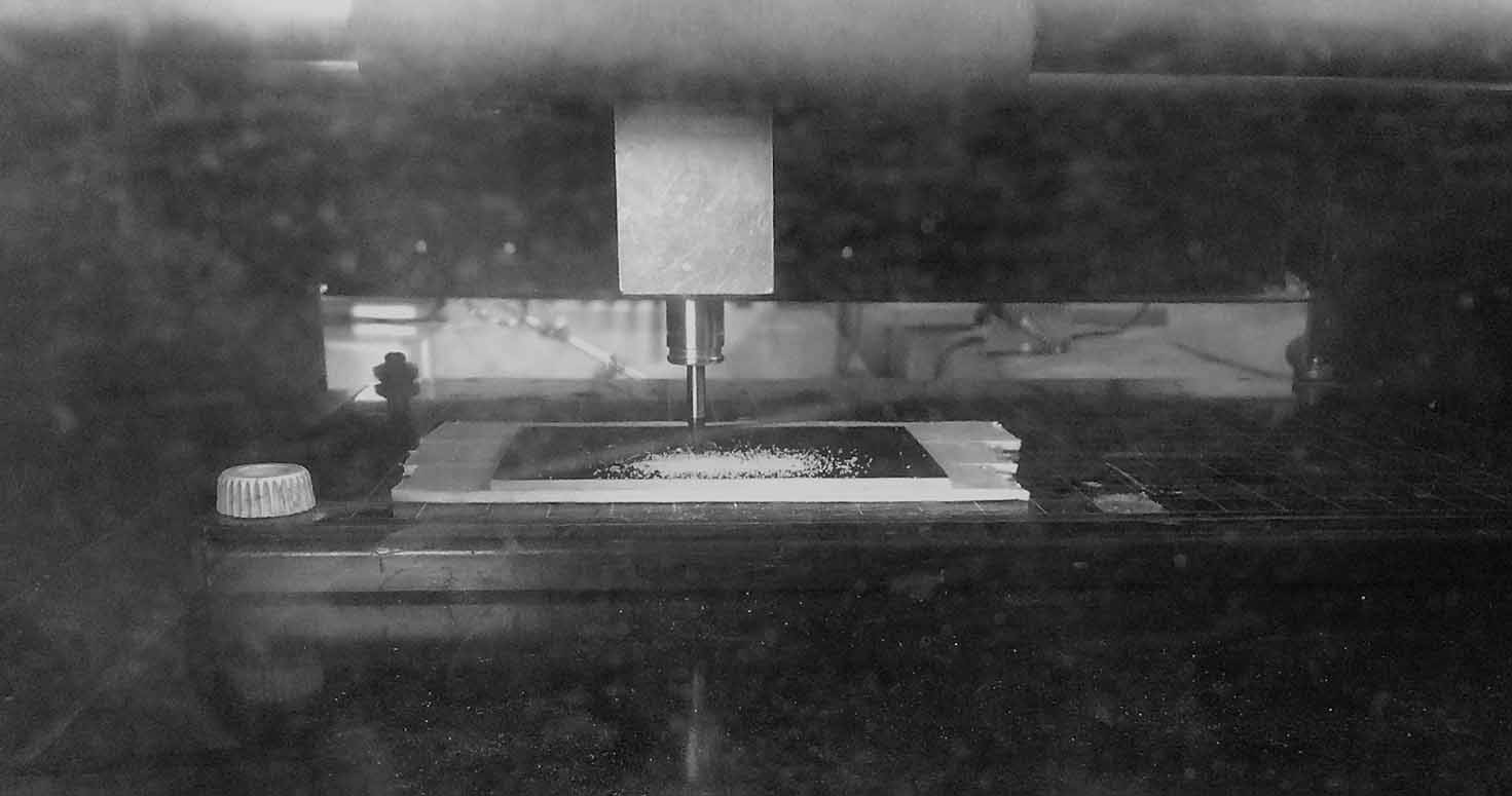
Milled my board in rolland Modella with 1/64 bit for tracing and cut by 1/32 bit.
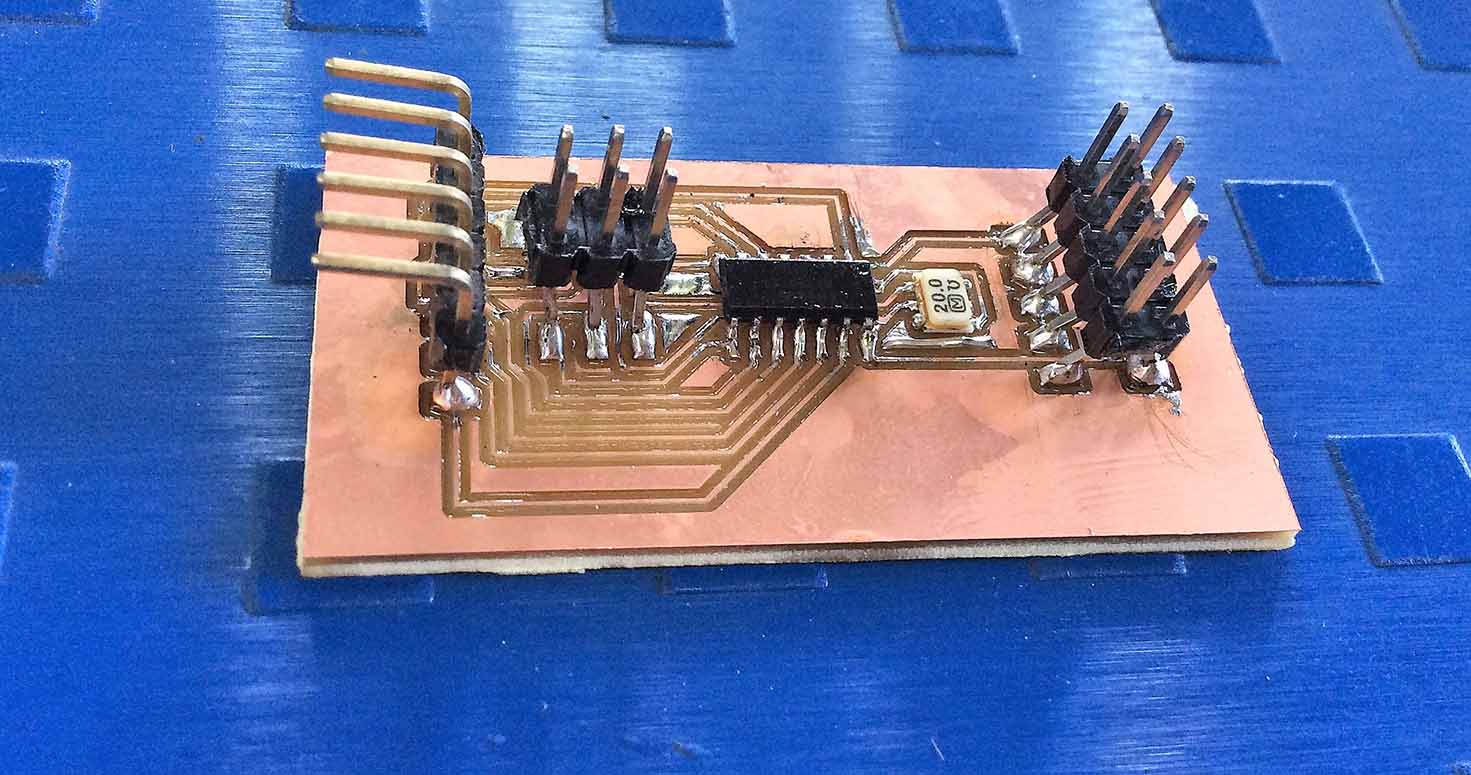
Populated my board and Programmed it with FabISP:
I had lot of complications, I kept trying programming my board but it failed to do so,at first it did light LED but then the second time LED was very low as if there is no power. So i checked my board with multimeter if its getting enough power, and i realised that my board is probably short from somewhere. I rechecked my connections, I realised that my path which was connecting my Pin VCC was out and the path hanging was touching GND, So i removed the path hanging and gave power through jumper junction through Arduino Vcc. Then my Led was lighting only single colour, i rechecked my coding. Then coding kept showing errors , suddenly Arduino IDE showed error to code uploading. So i attached FABISP to Suyogji's laptop and it still showed single colour, Well after long, one RGB LEd fused with fumes and we realised all the RGBs i used till now, there Red LED wasnt working.
So i then installed the below drivers so that my laptop recognises FabIsp, i installed drivers libusb-win32(v1.2.6.0) through Zadig, which were missing from my PC. Further i connected only Fabisp and my board , uploaded code and then again made conections. I was able to run it but again with the same error of showing only one colour, Then i found a new RGB Led, and well, there was a small error in my code too. But i was able to program it then. Board Running
Download code
Download Board
Download Board
BOARD 2 - ATmega 328
I have designed this board on Eagle, taking all the Components like Resistors, capacitors, Pin headers, Crystal, Atmega 328 IC , Leds etc. Made its Png file of the trace and cut.
Details about errors, designing and programming can be found on my final project page
Final project
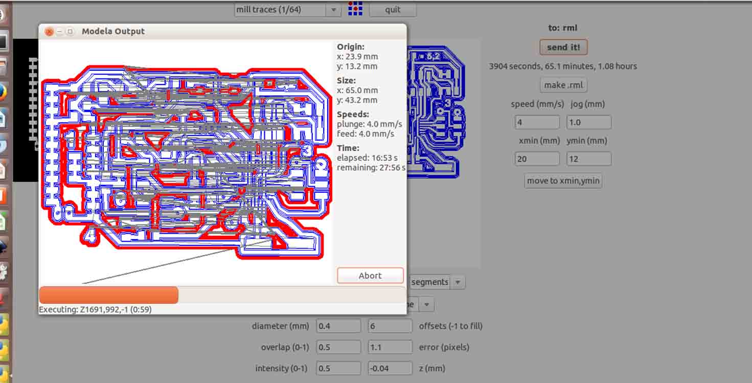
Milling it on offline Fab module, where I mill my board traces with 1/64 and cut file with 1/32 mill bit.
Video of 1/64 bit milling my traces.
Well, achieving this board is my biggest achievement in the Fab academy. Designing it, remilling it after connection errors and shots. and trying different ways of programming it because Atmega328 is not common to use in our fablab.
This moment was bliss
I used Arduino IDE to bootload my board. But for this I basically used an old version of IDE, Arduino 1.0 and edited its boards file , added this board in it and then was able to succesfully bootload. The process has been explained on Final project Page.
I learnt so much in these 3 weeks when i was working on this board 24/7 , i read datasheet for designing my own board, understanding each pin in detail, run things on Arduino and replicate it with the board and running on it.
In the video below you will see, I have explained how the process of the board works.
Here, Input is IR sensor and RFID tag
You can find the tutorial and walkthrough on my interface page
WEEK 16
Download Board
Download Schematic
Download code
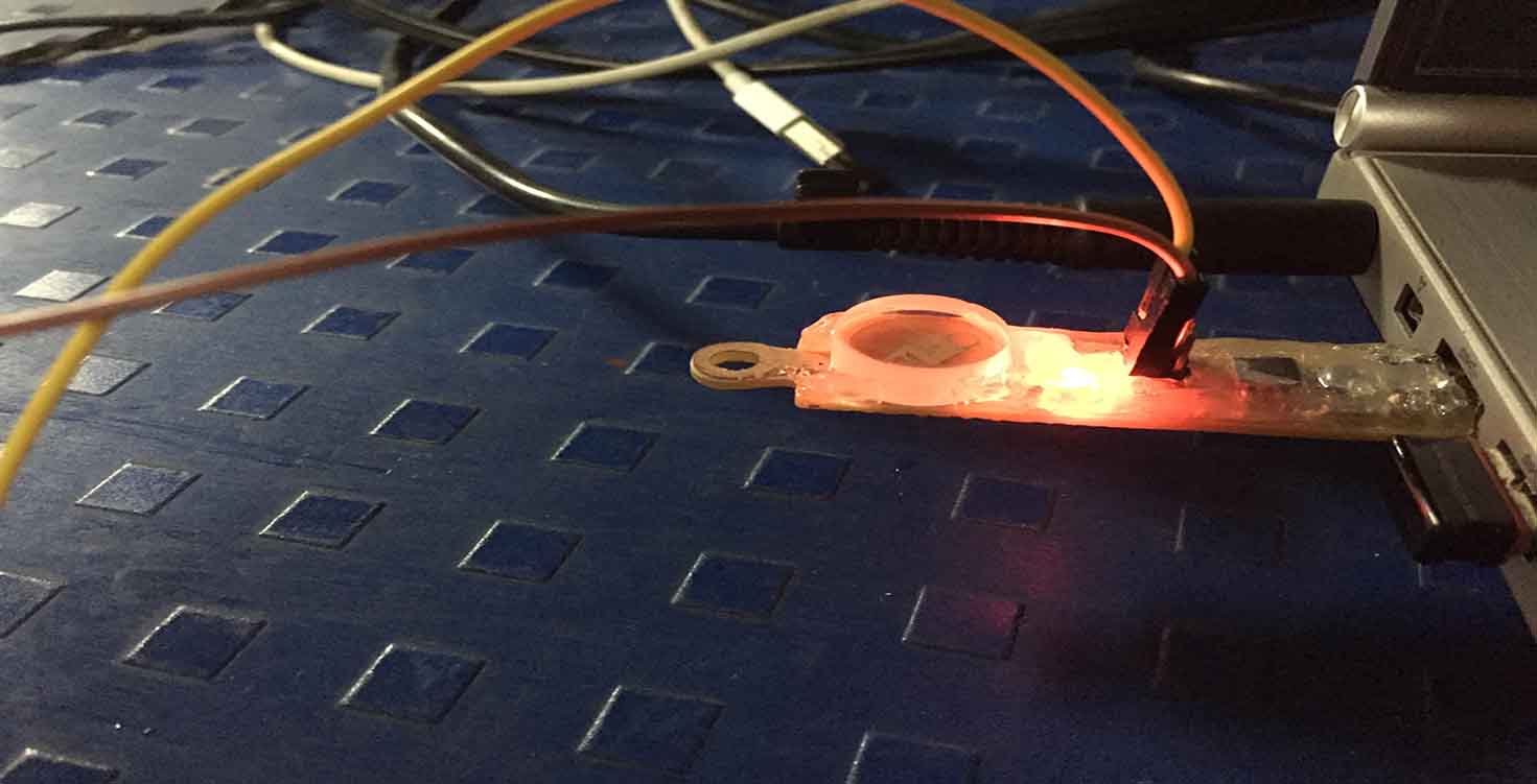
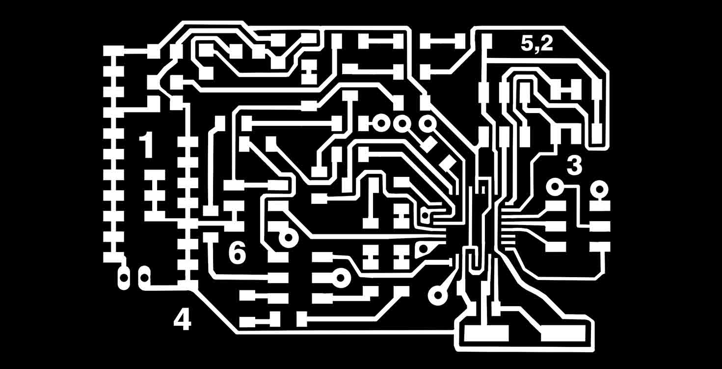
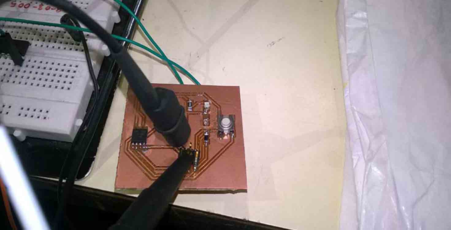
Attiny 45- Switch as Input
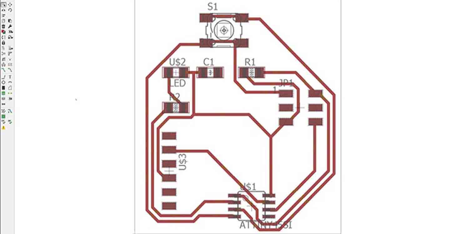
I Designed this board with the help of Neil's Button Input board. If you see below, i made a schematic of the same in Eagle. (where you set grid for yourself, add components and with the help of pencil, make connections). To avoid mess, you can connect GND with a tag name GNd and use that same tag everywhere you need GND conenction. Its prefered to do ERC, which is one of the best features of Eagle.
Thats the board file. So here you can do DRc if required. I basically Autorouted my board and
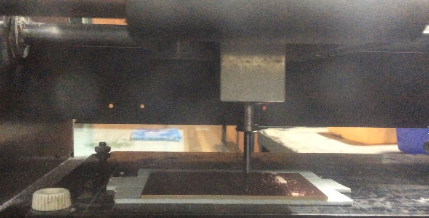
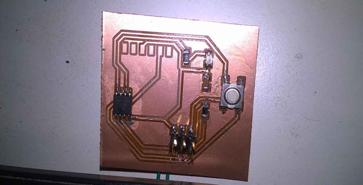
Milling my board with 1/64 bit and 1/32 performs the cut function.
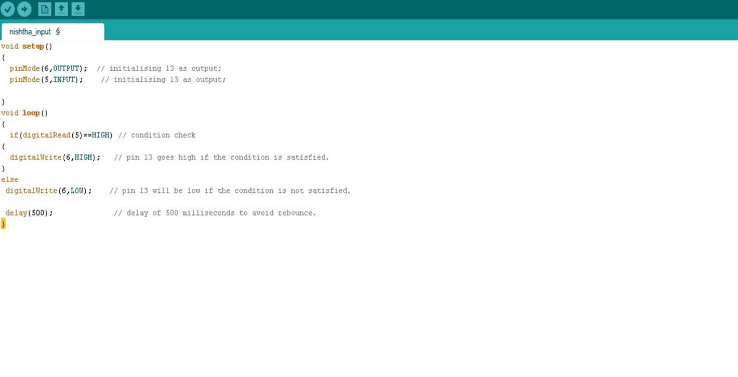
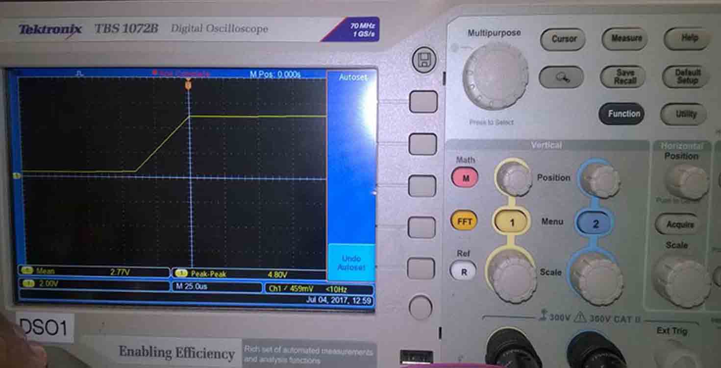
Programming through Arduino IDE, where when button pressed, Led lights up.
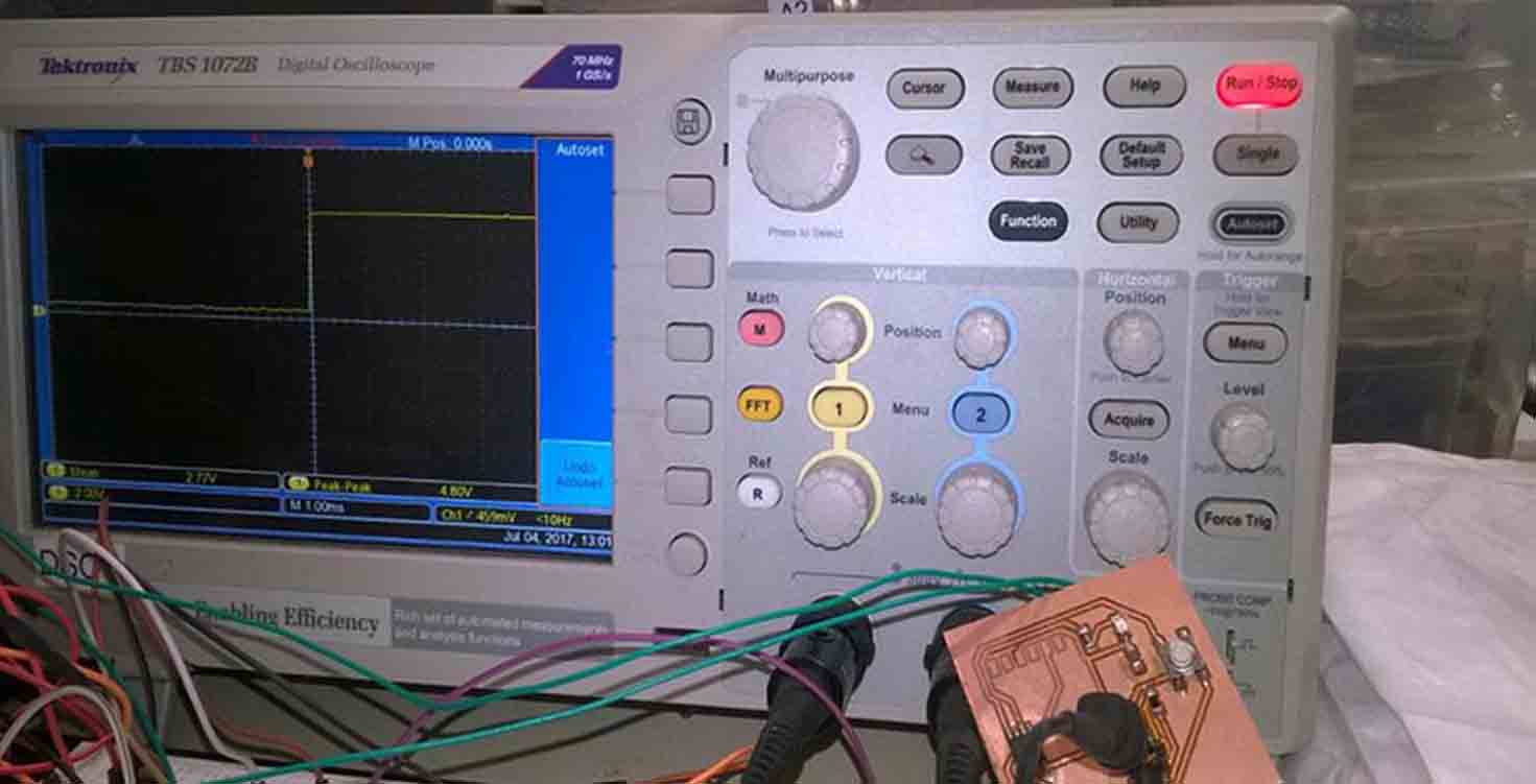
Here i am measuring my input with the help of Oscilloscope
STEPS:
1. Connect the probe with the Oscilloscope input channel 1(slightly rotate the joint until it perfectly connects with the input port).
2.Connect the pin(1) on the probe to the positive side of the resistor (or any component that you are asked to measure).
3. Then connect the ground(2) of the probe to the common ground in your circuit.
4 Click the “Auto Scale” button on the upper right corner of the function area.Now you should see a sine wave signal on the screen area.
Download Board
Download Schematic
3. Arduino Trials
First tried it on Arduino to understand how Ir works, So i connected Ir GND , VCC and Data pin to the Arduino.
I tried this in Week 10, where my input is IR and Output is Buzzer, similarly i did another with Ir where output was multicolour LED.
When ever Ir senses something, the buzzer will buzz. therefore, this one i tried for my final project.
Download codes
