NOTE: Vigyan Ashram is known as "Fablab 0" , it is one of the remotest labs with very minimal internet access , therefore, we have been using old version of Fab module which is an offline version.
WEEK 10
Output Device
Learning Outcomes:
WEEK ASSIGNMENT: Add an Output device to my Microcontroller board and program it
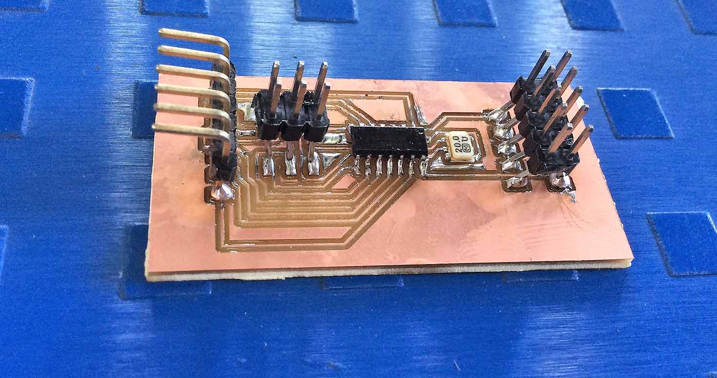
1. Making my output board with RGB Led as output
This week, we had to program a board for an output device, therefore i decided to do my assignment in regard to my final project.So that im able to improvise and implement my final projects. My final project is a tool management system with IR sensor and RGB LED. So this week i designed a board which can take two 2 IR sensor and 2 RGB LED,
COMPONENTS:
Well, Datasheet was very helpful to understand which conenctions to make where like Mosi(Master out , slave in) , Miso (Master in , slave out)
-IC (Integrated Circuit) Attiny 44
-Resonator
-3x2 pin header
-1x6 pin header
-2x5 pin header
- I used through hole RGB LED because in my project i am not using SMD RGB LED as it will be placed inside the box, which will light up the whole box.
I designed my board in Eagle, with the following steps:
Designing on Eagle
Designing on Eagle:Schematic
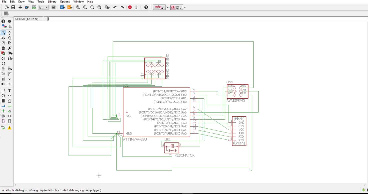
You can also do ERC in the schematic in tools, it checks for connection errors. You can explore details in Week 6
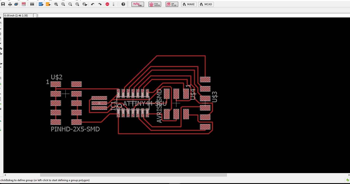
Switch to board : Board
In this part, we will Route the connections, Route means we will make route of the connections which modella will print. So there are two ways to do so:
One is, manual routing, you can do that by typing in the command line "ROUTE" and then connect according to your need but what i prefer is Auto routing, so just move your components on the board or given frame. and then go to TOOLS > AUTO ROUTE > Here, you will see different routes eagle made and you can select anyone, i selected one which had very less connections going below the IC because that decreases the chances of shots.
Download Board File
Download Schematic File
Download Code
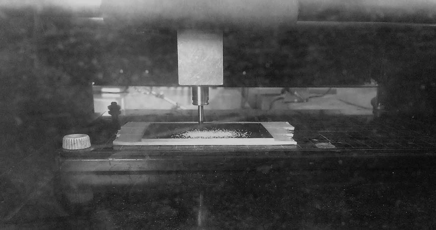
Milling with Rolland Modella
We use old offline version of fab module in ashram due to inconsistent internet availability. Opened terminal in ubuntu, typed
sudo fab
Select rolland modella and png. First , I milled traces with 1/64 mill, and 0.08 z and -1 offset.
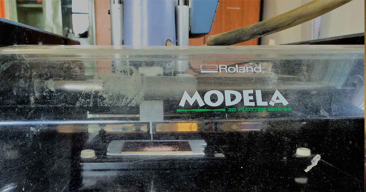

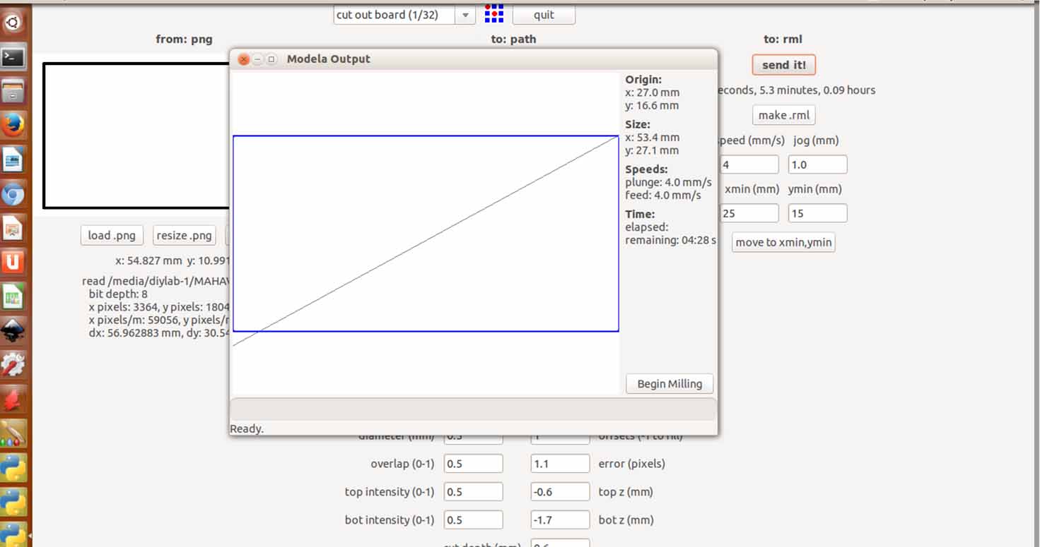
Then change milling bit to 1/32 and start milling, i made no changes because my file width was perfect to the diameter of the mill, in case your track is missing or not visible, decrease the diameter point wise like first try 0.78, then 0.76 till your track is visible.
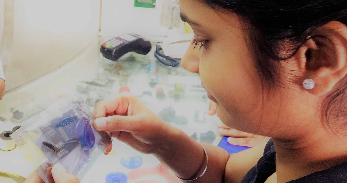
Well, this week is my favourite because i designed my own board with understanding the datasheet and proper components. I soldered my componenets with help of flux, soldering iron and soldering gun. Well, explore this skill by sitting calmly and with good light and explore the best way of soldering. This week, soldering was difficult too as i had an eyelid infection because of heat here so my whole left eyelid was swollen, so my soldering isnt perfect but yes yours can be !
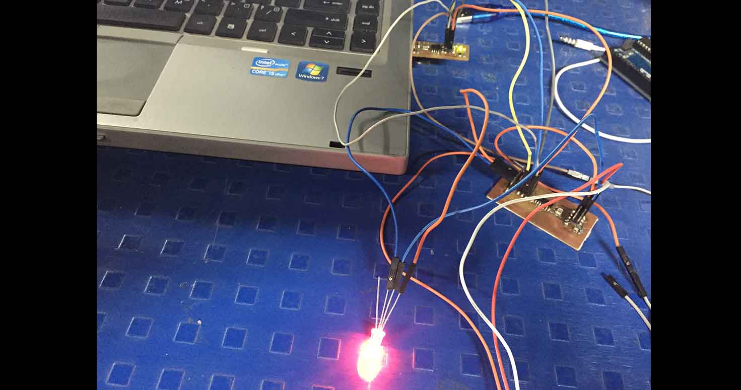
PROGRAMMING
So i uploaded this code for RGB LED :Open Arduino IDE, copy the code below if you looking forward to do whats in the video below.
Upload it- Select Port of Arduino- Arduino as ISP as I am using my board.
I havent done RGB before so i didnt knew it had three color legs and one GND , also the coding for the same i made with lot of trials and errors, after taking it from the internet.
// the setup routine runs once when you press reset:
void setup() {
  // initialize serial communication at 9600 bits per second:
  //Serial.begin(9600);
  pinMode(9,OUTPUT);
  pinMode(10,OUTPUT);
  pinMode (8, INPUT);
}

// the loop routine runs over and over again forever:
void loop() {
  // read the input on analog pin 0:
  int sensorValue = digitalRead(8);
  // print out the value you read:
  //Serial.println(sensorValue);
  //delay(10);        // delay in between reads for stability


  if(sensorValue ==1)
  {
  //  LED(50);
  digitalWrite(10, HIGH);
  digitalWrite(9,LOW);
  }

  else
  {
    digitalWrite(9,HIGH);
    digitalWrite (10, LOW);

    }


}
2. Making a TriShat Kit
While doing this, i figured out hierarchy of my boards in my final project and decided to Make a sashatkit for my final project which will be connected to another Middle board which i will design and will handle IR sesnsors and Leds of my different Tool holders.
Therefore, I wanted to design something wherein if anyone/ashram because ashram will be implementing this system. If anyone wants to expand the tool system from 10 to 50 tool holders then they need to have some solution.
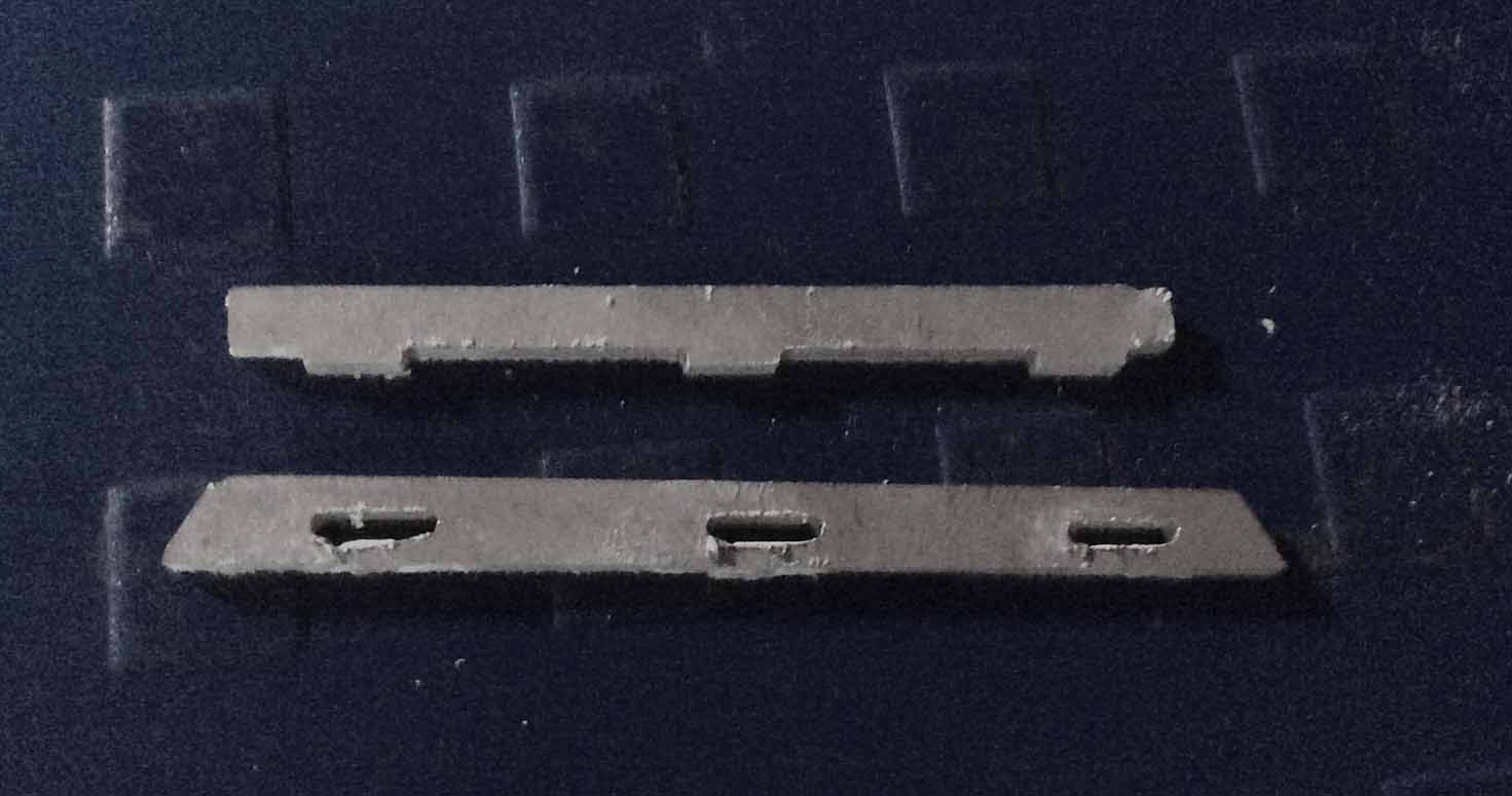
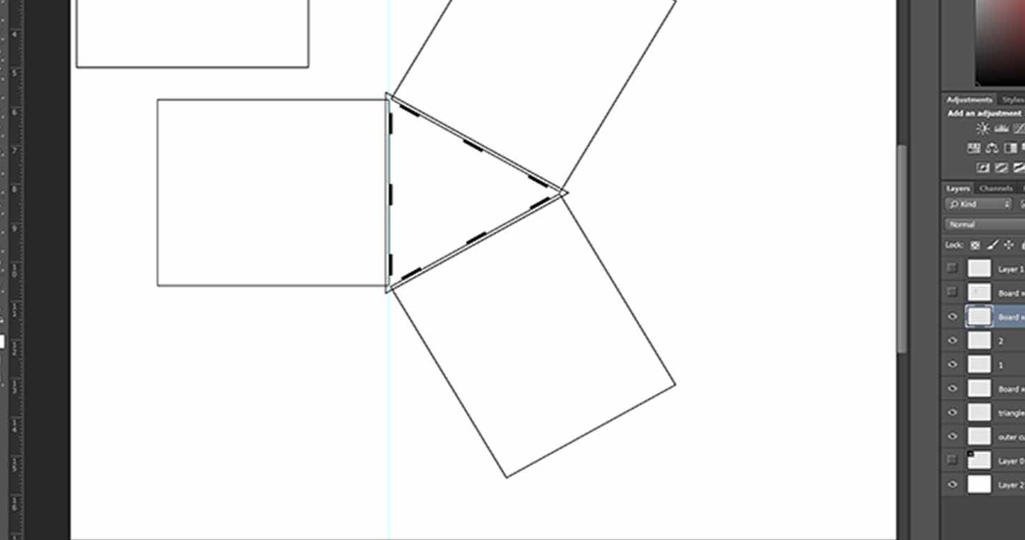
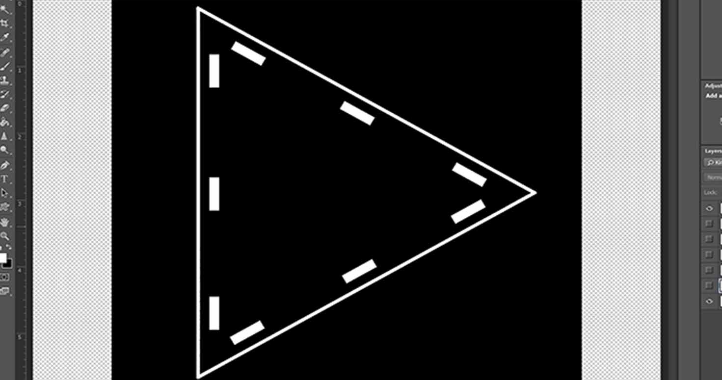
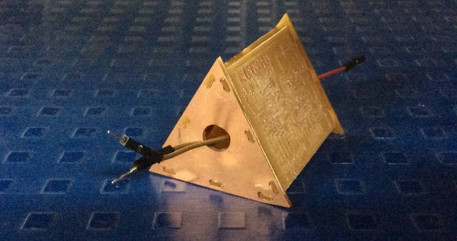
Therefore, I designed a kit named TriSat , where in i have pressfit three Satshas with a provision of Wires coming out for connection.
I designed this kit for 4 major purposes:
1. To expand tool management system.
2. People can use this design for any boards and conenct them together, also two projects can be compiled together through this design.
3. To bring in the kit where people can collaborate and solder together on this board together which will help a team to understand and learn from other about their soldering skills and their project.
4. It acts like Solder stand.
I first tried a pressfit on pcb.
I designed these pressfit to check right press fit, i did this on modella.
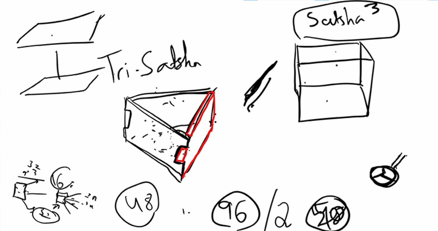
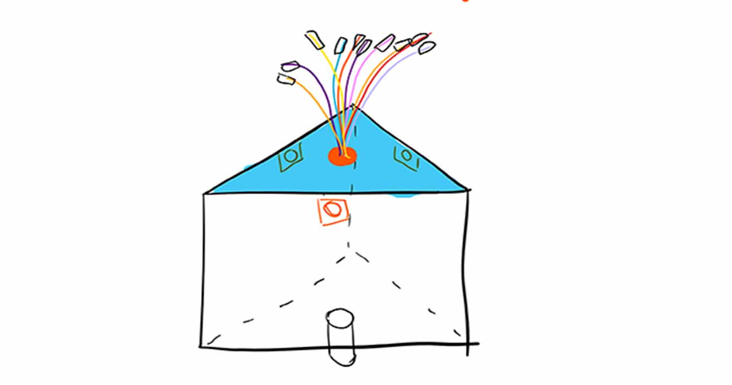
Trishat will be used in my final project, where i will pressfit my Atmega 328 on one side , other side attached to the wall, with a Buzzer embedded inside.
Also, inspired by this design , my classmate Mahavir Singh, designed another CUBOID which not only has a design but also gives solution to how to connect different boards together with an inbuilt programmer. Well, check that out.
Milled Satshakit for Machine
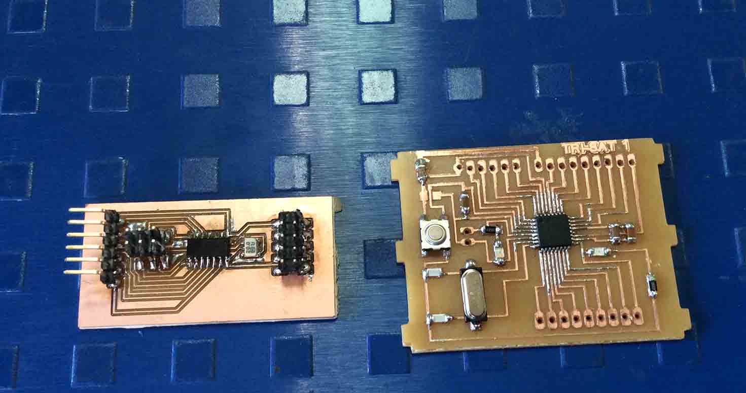
Trying to run, was able to run blink program but my board got fused while trying it to use for Make a machine, for which i made this board
Download Satshakit Board file
Download Satshakit Schematic File
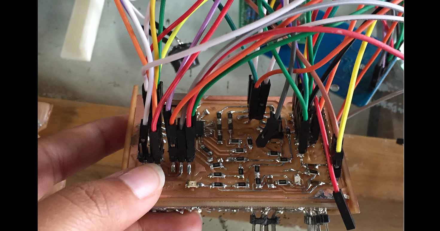
3. Atmega 328 board
I designed Atmega 328 board for many devices like buzzer, RFId, RTC (for future), Sd card (for future), IRs, LEds.
Download board Atmega File
Download board Atmega File
Download Code Atmega File
4. Trying other outputs with Arduino
To start with, i started by programming a normal LED with arduino solely by typing code and not with help of an example to understand every element we type for coding. Because i realised in my Tool managment Project i will have to add different elements and program them together , therefore it is essential to learn from basics, as i did program in embedded programming so i knew how to use arduino.
Thanks to Swarnaji for repeating the class i missed when i went for Phd and helping me learn programming.
So i used following for learning programming
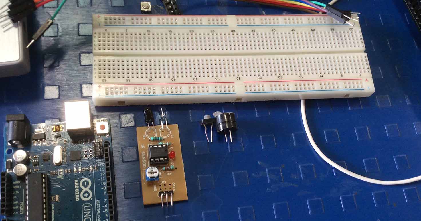
LED and Button:
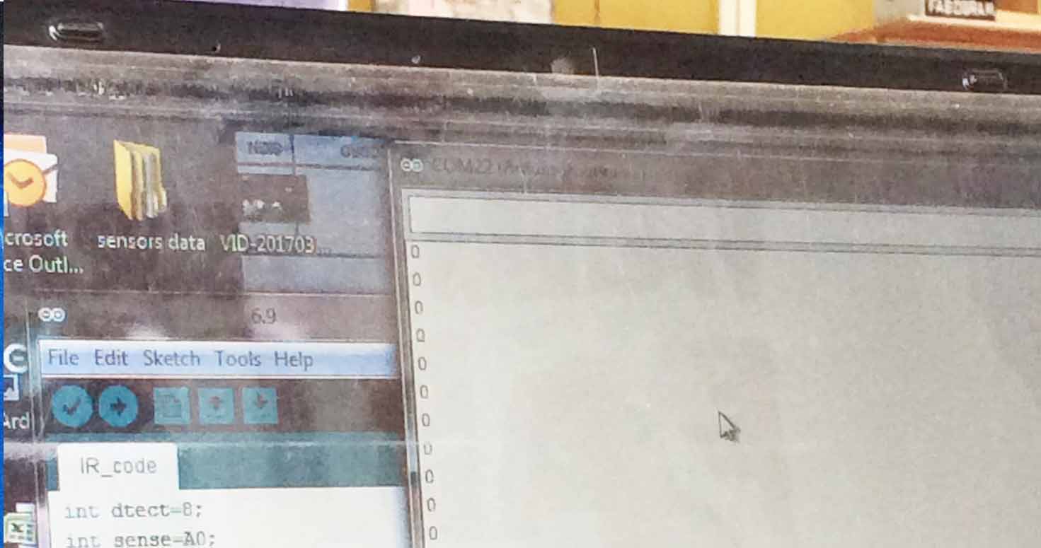
Then i went ahead programming IR sensor, understand how it works, it was great to finally try my hands and learn its process.
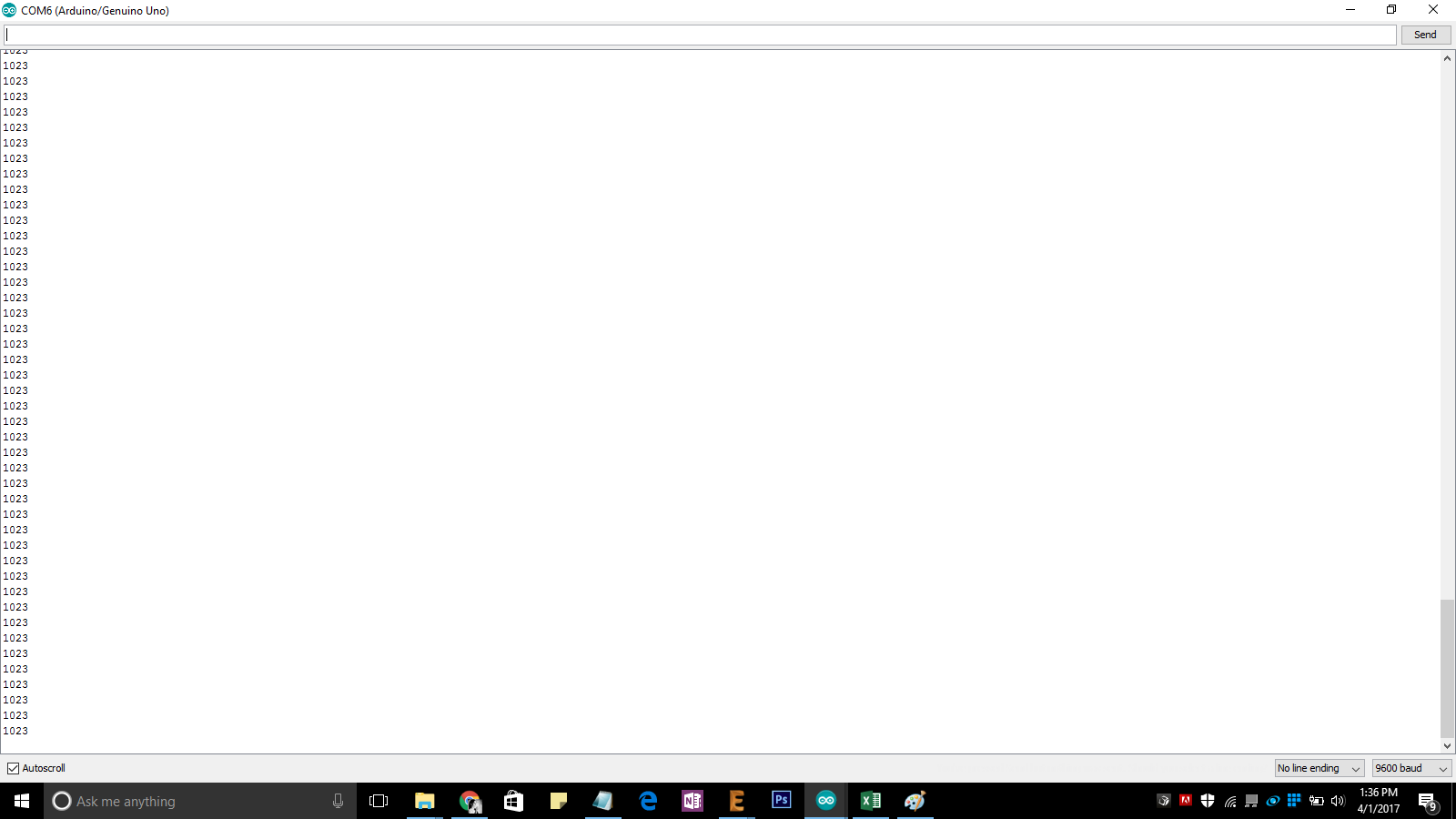
The serial monitor was showing 1023 continously as we did Analog but then we changed it to digital and thats what we received.
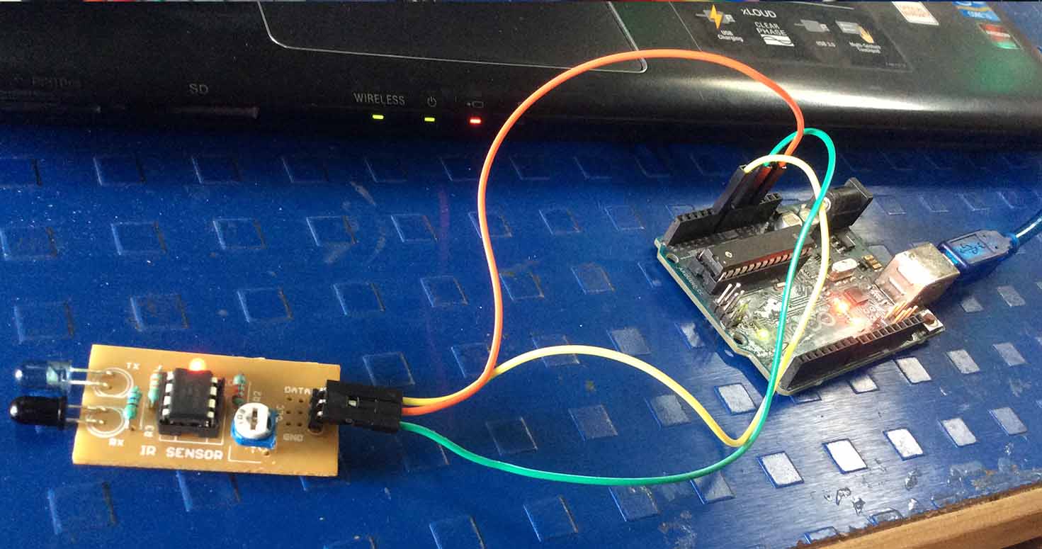
Programmed Buzzer, where when Ir senses some movement , the buzzer rings:
                // the setup routine runs once when you press reset:
void setup() {
  // initialize serial communication at 9600 bits per second:
  Serial.begin(9600);
  pinMode(9,OUTPUT);
}

// the loop routine runs over and over again forever:
void loop() {
  // read the input on analog pin 0:
  int sensorValue = digitalRead(7);
  // print out the value you read:
  Serial.println(sensorValue);
  delay(10);        // delay in between reads for stability


  if(sensorValue ==1)
  {
  //  buzz(50);
  digitalWrite(9, HIGH);
  }

  else
  {
    digitalWrite(9, LOW);

    }


}
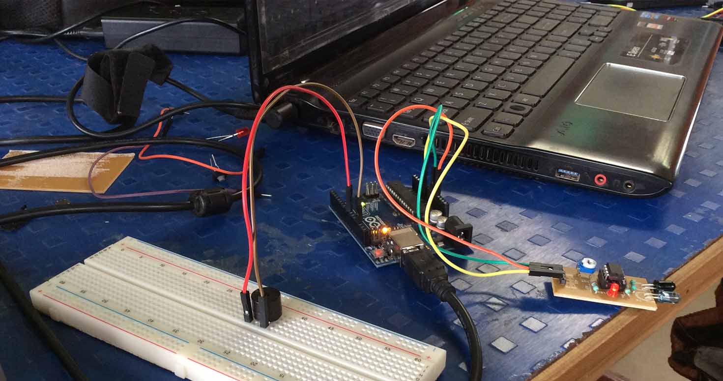
Then i connected IR, Buzzer and a switch, where Switch acted like RFID, so if someone makes movement near Ir then buzzer will make noise, if I press the switch and then make movement , buzzer will not buzz. Therefore, If someone scans his/her tag on RFID scanner, and then Ir senses movement, it will not buzz the buzzer but it will if someone doesnt scans and makes movement near IR.
  const int buttonPin = 2;     // the number of the pushbutton pin
int buttonState = 1;         // variable for reading the pushbutton status

// the setup routine runs once when you press reset:
void setup()
{
  // initialize serial communication at 9600 bits per second:
  Serial.begin(9600);
  pinMode(9,OUTPUT);
  pinMode(buttonPin, INPUT);
}

// the loop routine runs over and over again forever:
void loop()
{
    buttonState = digitalRead(buttonPin);
    // Serial.println(buttonState);
    // read the input on analog pin 0:
    int sensorValue = digitalRead(7);

    if(buttonState == 1)
    {
      if(sensorValue ==1 )
        {
          // print out the value you read:
            Serial.println(sensorValue);
            delay(10);        // delay in between reads for stability
            digitalWrite(9, HIGH);
        }
      else if (sensorValue == 0)
        {
            digitalWrite(9, LOW);

        }
    }
    else
    {
      digitalWrite(9, LOW);
    }
}
Then we didnt had RGB Led in the inventory so one of the kids gave me a multicolour LEd, so i tried programming Multicolor LEd and IR sensor, though i wanted to program in such a way that if someone makes a movement Red Led should blink , otherwise RED.
4. Others
Beside that, I also went to buy components for ashram , make a machine and our final projects, we accompanied suhasji to the pune city to see what are the other possibilities to our projects.
Explored about RFID's, Ill be using this for my first interfacing.