What are Input Devices ?
Input Device is a piece of hardware which is used to provide data and control signals to microcontroller/processor in order to perform a task. This leads to the results of data processing carried out by an information processing system (such as a microcontroller) and the data will be logged in system using that we can perfrom the respective task linked to that data set
Thus it results Input Devices provide data and control signals. Any of the following components may be used as Input Devices:
Workflow of making board and implimenting the sensor
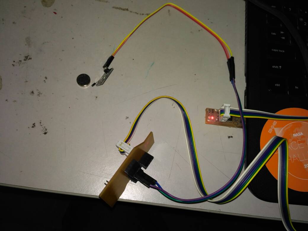
i have used the board prepared in the previous week week10 as i have made it as multi functional board as i have given all the pinouts
This week intially thought to use the GY-521(Accelerometer and gyro sensor),but it was working on I2C protocol i have no idea about it when i have asked my instructor Yadu suggested it will be taught in the networking week then i have used a Hall Effect sensor for my this week to detect the magnet
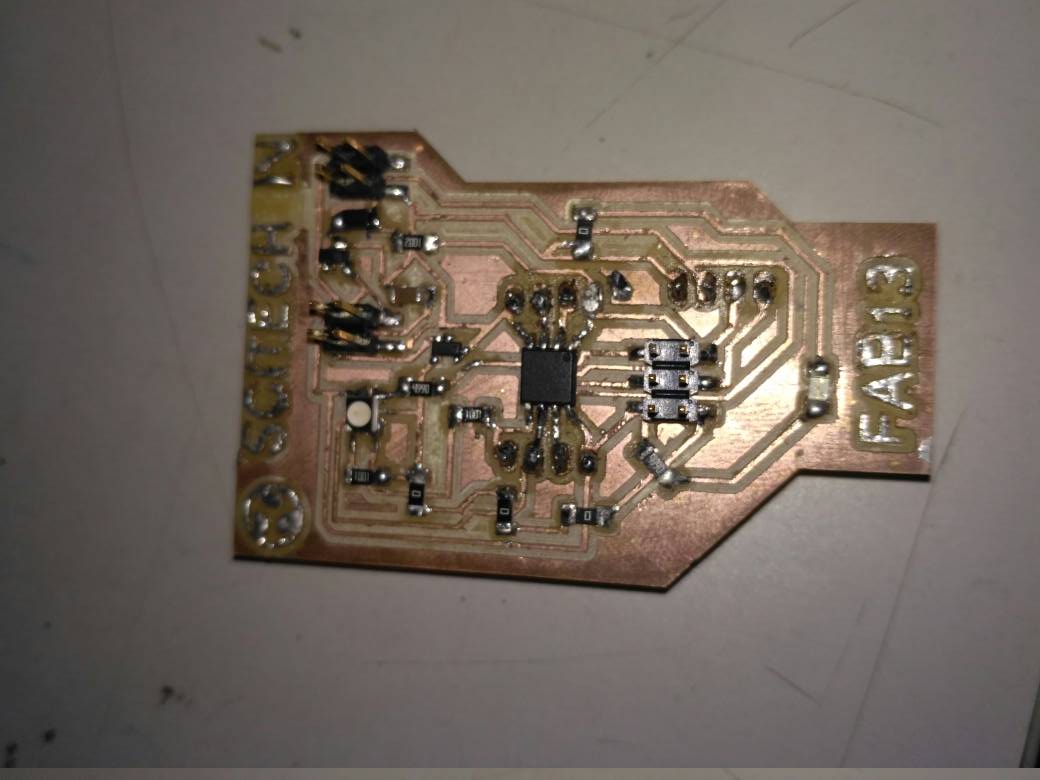
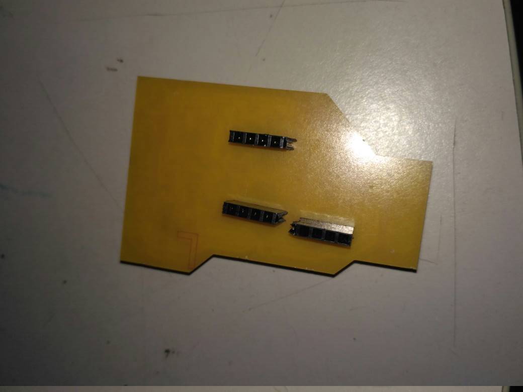
Soldered board for testing and header pinouts for connecting devices
Hall Effect Sensor
Magnetic sensors are designed to respond to a wide range of positive and negative magnetic fields in a variety of different applications and one type of magnet sensor whose output signal is a function of magnetic field density around it is called the Hall Effect Sensor.
Hall Effect Sensors are devices which are activated by an external magnetic field. We know that a magnetic field has two important characteristics flux density, (B) and polarity (North and South Poles). The output signal from a Hall effect sensor is the function of magnetic field density around the device. When the magnetic flux density around the sensor exceeds a certain pre-set threshold, the sensor detects it and generates an output voltage called the Hall Voltage, VH. Consider the diagram below.
A Hall effect sensor is a transducer that varies its output voltage in response to a magnetic field. Hall effect sensors are used for proximity switching, positioning, speed detection, and current sensing applications
Hall Effect Sensor Principals
Hall Effect Sensors consist basically of a thin piece of rectangular p-type semiconductor material such as gallium arsenide (GaAs), indium antimonide (InSb) or indium arsenide (InAs) passing a continuous current through itself. When the device is placed within a magnetic field, the magnetic flux lines exert a force on the semiconductor material which deflects the charge carriers, electrons and holes, to either side of the semiconductor slab. This movement of charge carriers is a result of the magnetic force they experience passing through the semiconductor material.
As these electrons and holes move side wards a potential difference is produced between the two sides of the semiconductor material by the build-up of these charge carriers. Then the movement of electrons through the semiconductor material is affected by the presence of an external magnetic field which is at right angles to it and this effect is greater in a flat rectangular shaped material.
The effect of generating a measurable voltage by using a magnetic field is called the Hall Effect after Edwin Hall who discovered it back in the 1870’s with the basic physical principle underlying the Hall effect being Lorentz force. To generate a potential difference across the device the magnetic flux lines must be perpendicular, (90o) to the flow of current and be of the correct polarity, generally a south pole.
The Hall effect provides information regarding the type of magnetic pole and magnitude of the magnetic field. For example, a south pole would cause the device to produce a voltage output while a north pole would have no effect. Generally, Hall Effect sensors and switches are designed to be in the “OFF”, (open circuit condition) when there is no magnetic field present. They only turn “ON”, (closed circuit condition) when subjected to a magnetic field of sufficient strength and polarity.
Read More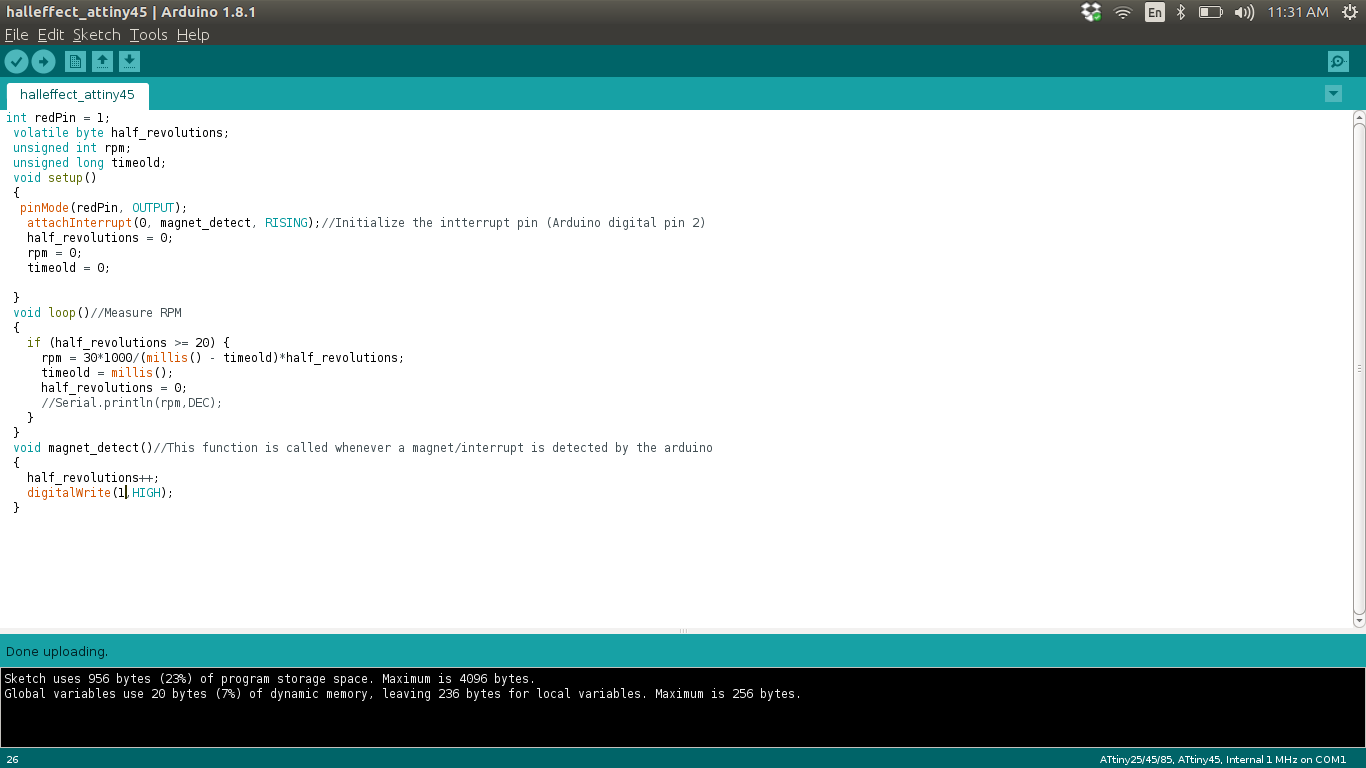
code Implimentation of Hall-effect sensor with my board
Implimentation of Hall-effect sensor with my board
  int redPin = 1;
   volatile byte half_revolutions;
   unsigned int rpm;
   unsigned long timeold;
   void setup()
   {
    pinMode(redPin, OUTPUT);
     attachInterrupt(0, magnet_detect, RISING);//Initialize the intterrupt pin (Arduino digital pin 2)
     half_revolutions = 0;
     rpm = 0;
     timeold = 0;

   }
   void loop()//Measure RPM
   {
     if (half_revolutions >= 20) {
       rpm = 30*1000/(millis() - timeold)*half_revolutions;
       timeold = millis();
       half_revolutions = 0;
       //Serial.println(rpm,DEC);
     }
   }
   void magnet_detect()//This function is called whenever a magnet/interrupt is detected by the arduino
   {
     half_revolutions++;
     digitalWrite(1,HIGH);
   }
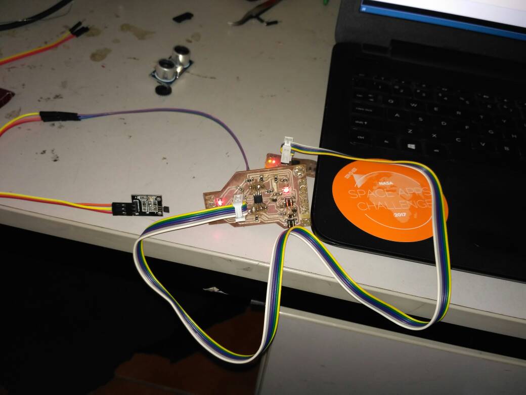
Hero Shot
Now here we comes to the Hero Shot of this Week
Implimentation of Input Device
