ASSIGNMENT
Project Development
Have you answered these questions:
- what is the deadline? How much time do I have left?
- what tasks have been completed, and what tasks remain?
- how will I complete the remaining tasks in time?
- what has worked?
- what hasn't?
- what questions still need to be resolved?
- what have you learned?
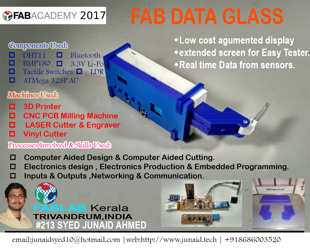
This week i started my final project development, ordered the componenets for my Fab DATA GLASS and started designing. My final project presentation page is shown beside introduction tab
1. What is the deadline? How much time do I have left?
For doing the entire project i have made a shedule in tabular format. Our project presentation is on 19 June 2017, this is 7th June 2017 and we have only 12 days to present. I am planning to finish it by 17th June 2017.
2. What tasks have been completed, and what tasks remain?
I will share the shedule here in that you can find what is the time limit i have given to complete each task.
FAB DATA GLASS Work Schedule
| Sl.No | Activity | Sheduled date | Status |
|---|---|---|---|
| 1 | Components collection | 28 May 2017 | completed on 01 June 2017 |
| 2 | PCB designing | 05 June 2017 | Completed on 10 June 2017 |
| 3 | PCB Milling and soldering | 07 June 2017 | On going process |
| 4 | Programming and Testing | 10 June 2017 | NA |
| 5 | Case Design and 3D printing | 12 June 2017 | NA |
| 6 | Integration & Testing | 14 June 2017 | NA |
| 7 | Carry Case design and fabrication | 16 June 2017 | NA |
| 8 | Documentation and poster making | 17 June 2017 | NA |
3. How will I complete the remaining tasks in time?
As per the above shedules, currently i am delayed by almost three days, Actually my PCB Designing took more time because i was thinking to design the board in small formfactor and that took me time and i was able to get the size as expected Our presentation is on 19th June and i am planned to finish it on 17th june, so maximum with in 18th june i have time to finish it. I planned to work extra time on each day to counter balance the delays. Currently i am spending almost 15 hours per day for the development .
4. What has worked?
soldering and continuity checks are on going. Started the programming on the arduino pro mini to understand the programming ,easy to port on the board which i am going to build, i am able to program the board to display test on the OLED which is showed in my project documentation. Now i have to go to the actual board and to do learning, edit and finally to program the board.
5. What hasn't?
I am currently going through the 3D Designing , once the board is designed and solderd perfectly i can design the case for my data glass it was little problematic ,and also i was unable to find the optics sutable so i had to figure out in which way i can make my optics workout.
6. What questions still need to be resolved?
I have to make the reflective surface and also i have to find a mirror to make the optics perfect,i am still figuring out it,I thought to finish basic functions as only display the data from sensors and will do implimentation of bluetooth later.
7. What have you learned?
Still i am continuing in working with different processes and machines, what i learned in this week is to make a double side board in modela machine. The 3D design of my case is going in rhinoceros and finding correct refelctor material is on going. It was a different experience from regular college experience.
Introduction
I had intially thought to make a access control system for the fablab tools and machines using NodeMCU and but later i have changed my idea to build a Low Cost Augmented display and the previous ideas concept image and current project Concept image can be found Here
I wanted to know the current temprature and Humidity ,Pressure and Altitude and Light Intensity data with out looking into the mobile and also i wanted to connect my device with the my fellow fabber Ajith's Project to get the data from the Easy Tester via bluetooth but due to lack of time i am doing it in a spiral development so i have planned to restrict myself till the getting data from the sensors,but in future i am going to continue the project that can be found here on my Github Repo.The process and the skills shown in the fabrication are fulfilling the Requirements of the complete final Project .
Processed Involved
Here i am going to explain what all process i have gone through to fabricate my FAB DATA GLASS
Electronic Design
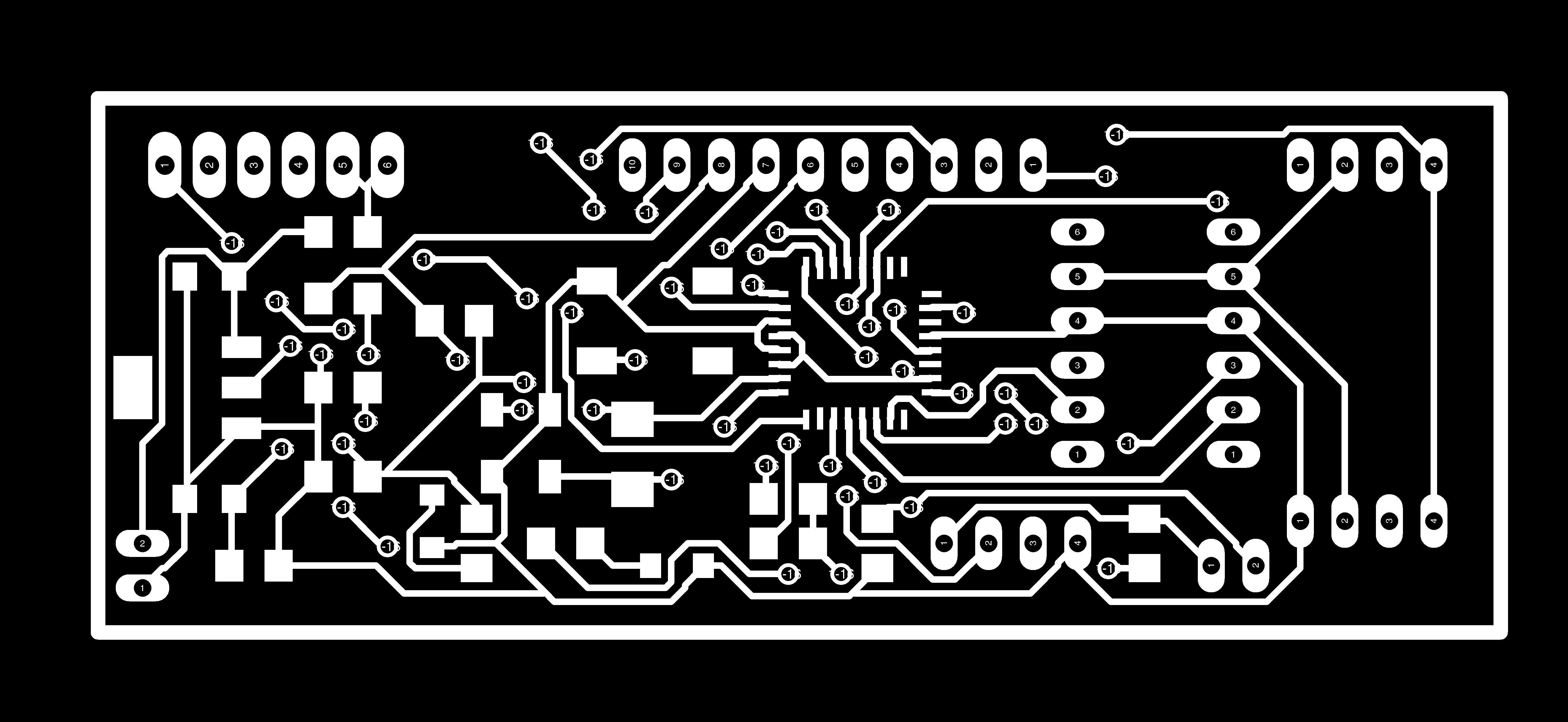
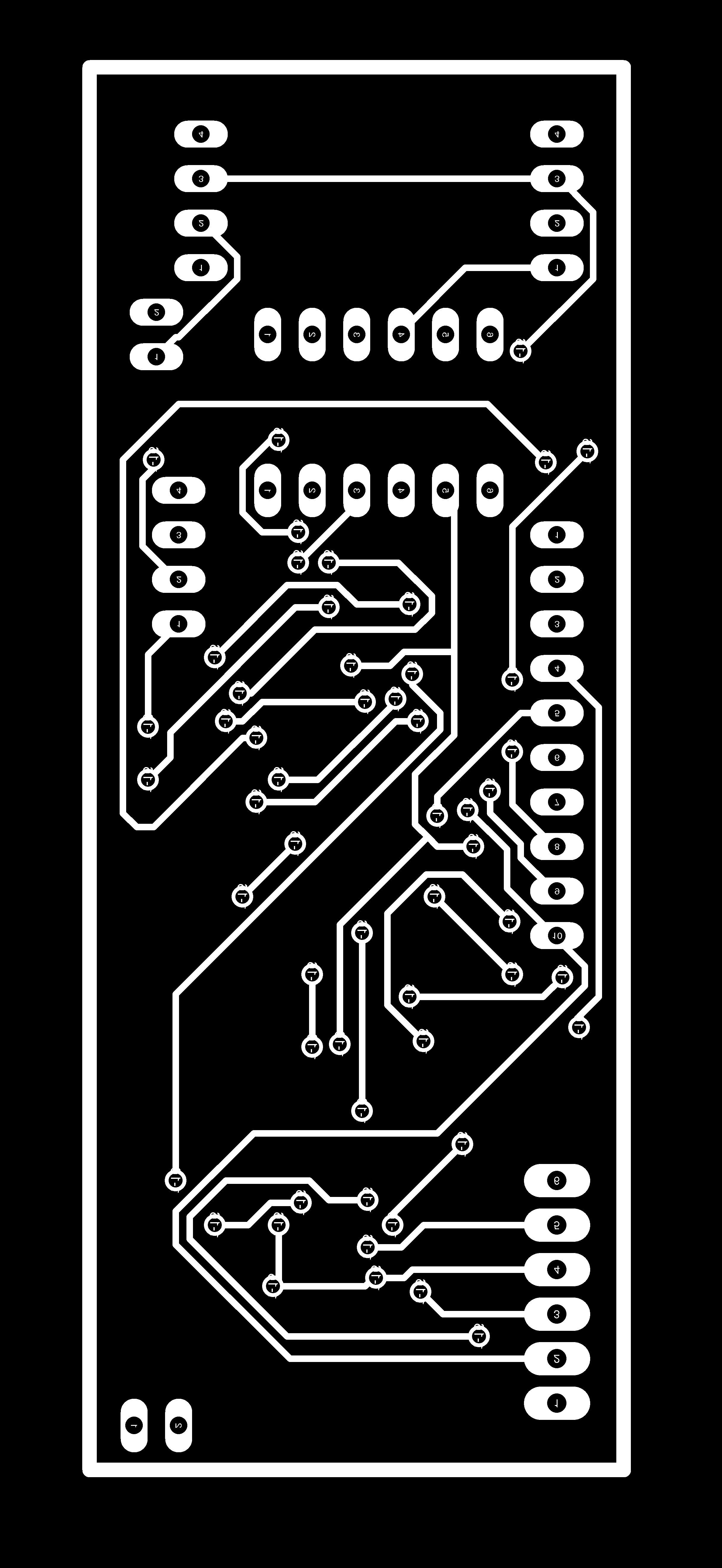
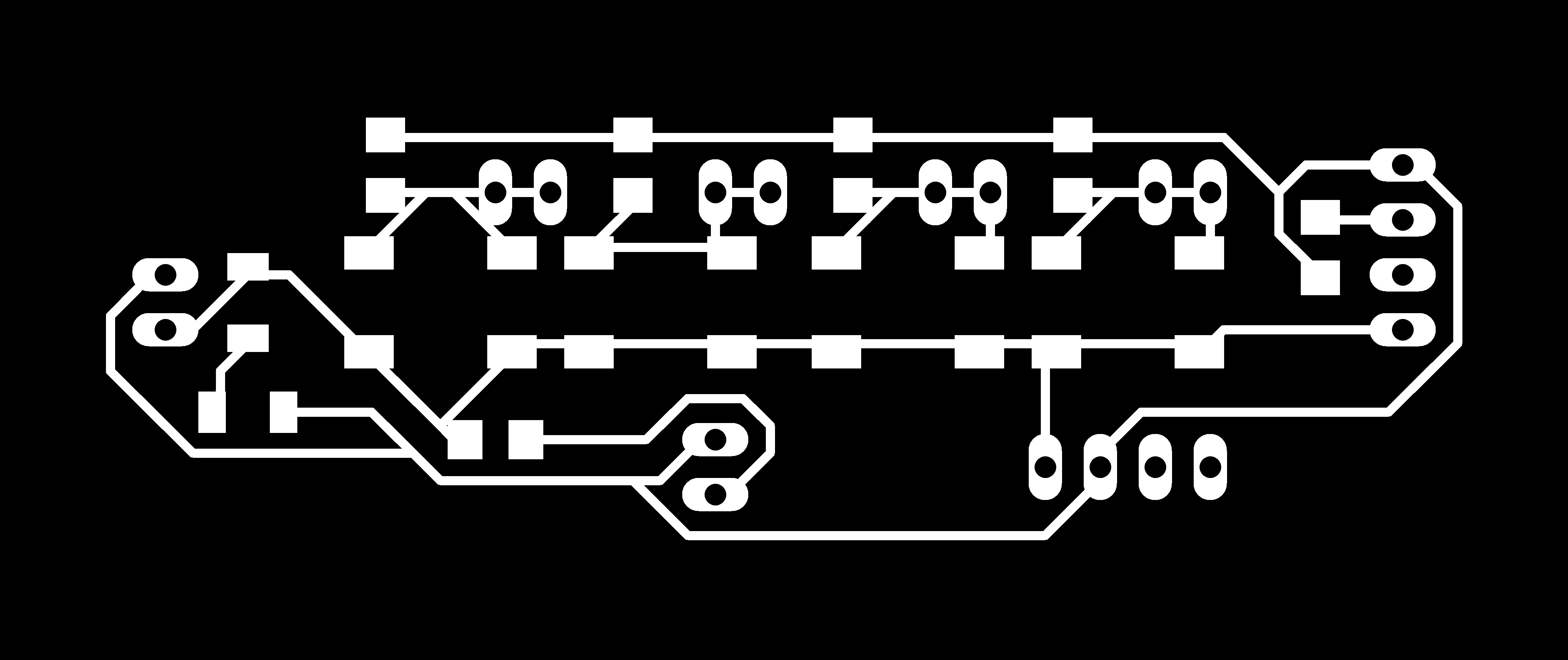
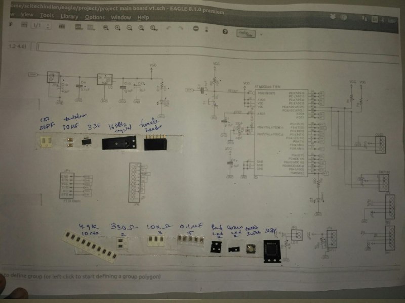
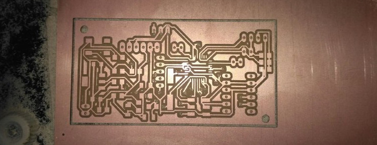
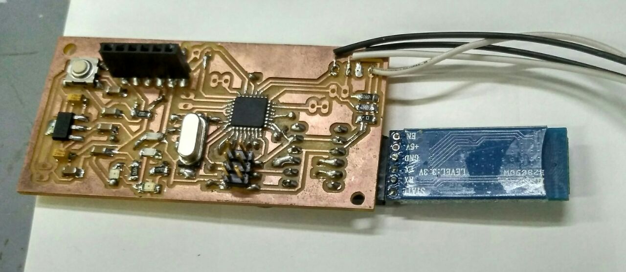
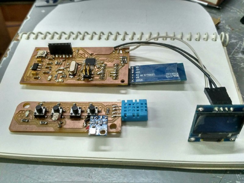
I have designed a board using the ATMega328P AU ,in the form factor of the 30mmx80mm and i was able to design the board using the Autodesk Eagle Software i have decided to make the double sided PCB as the formfactor is small ,i have applied the DRC accordingly and i have done the auto route then i was able to sucessfully design the board
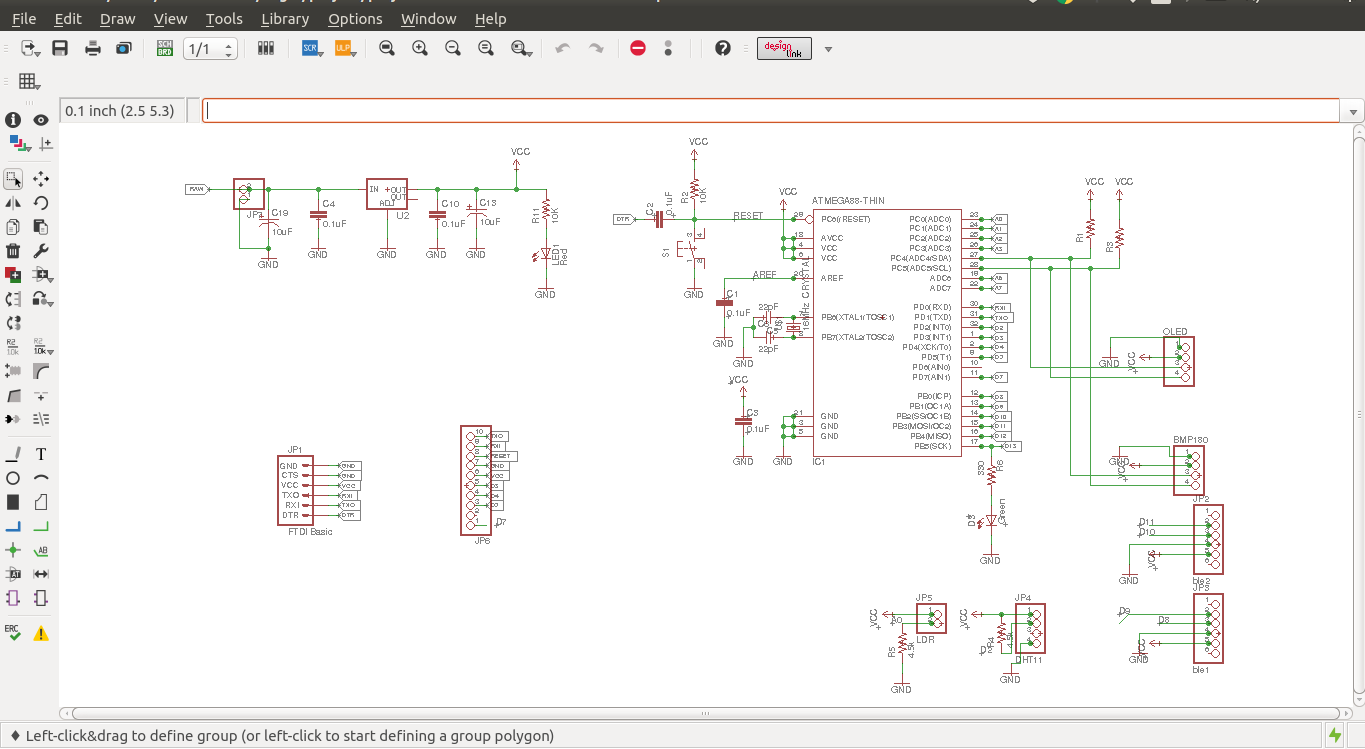

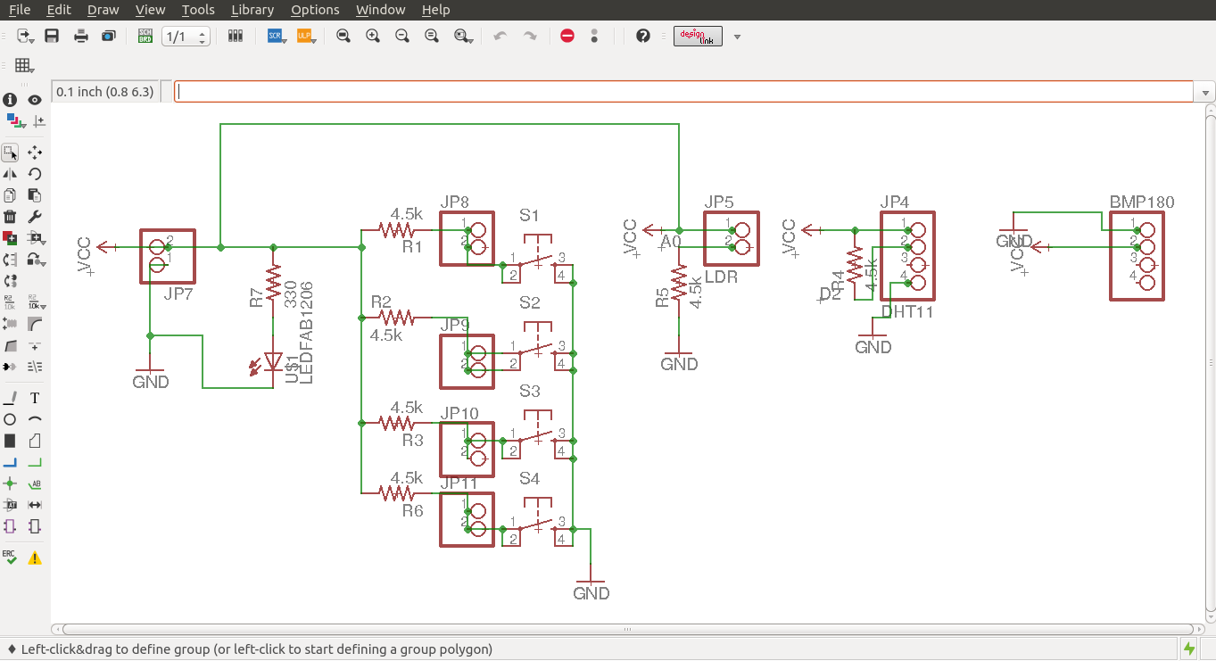
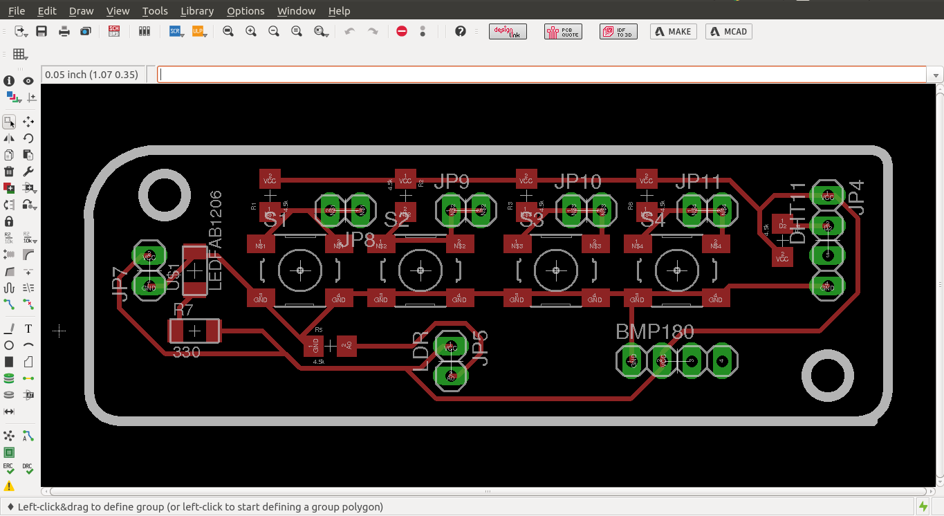
Now i have to design my sensor and switch board for which i have placed the all components and done the manual routing as there are very less components here you can see the schematics and board design
Electronics Production
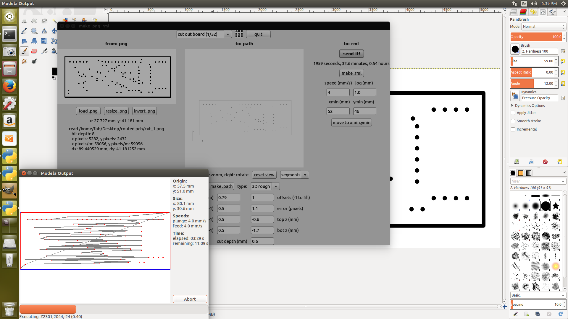
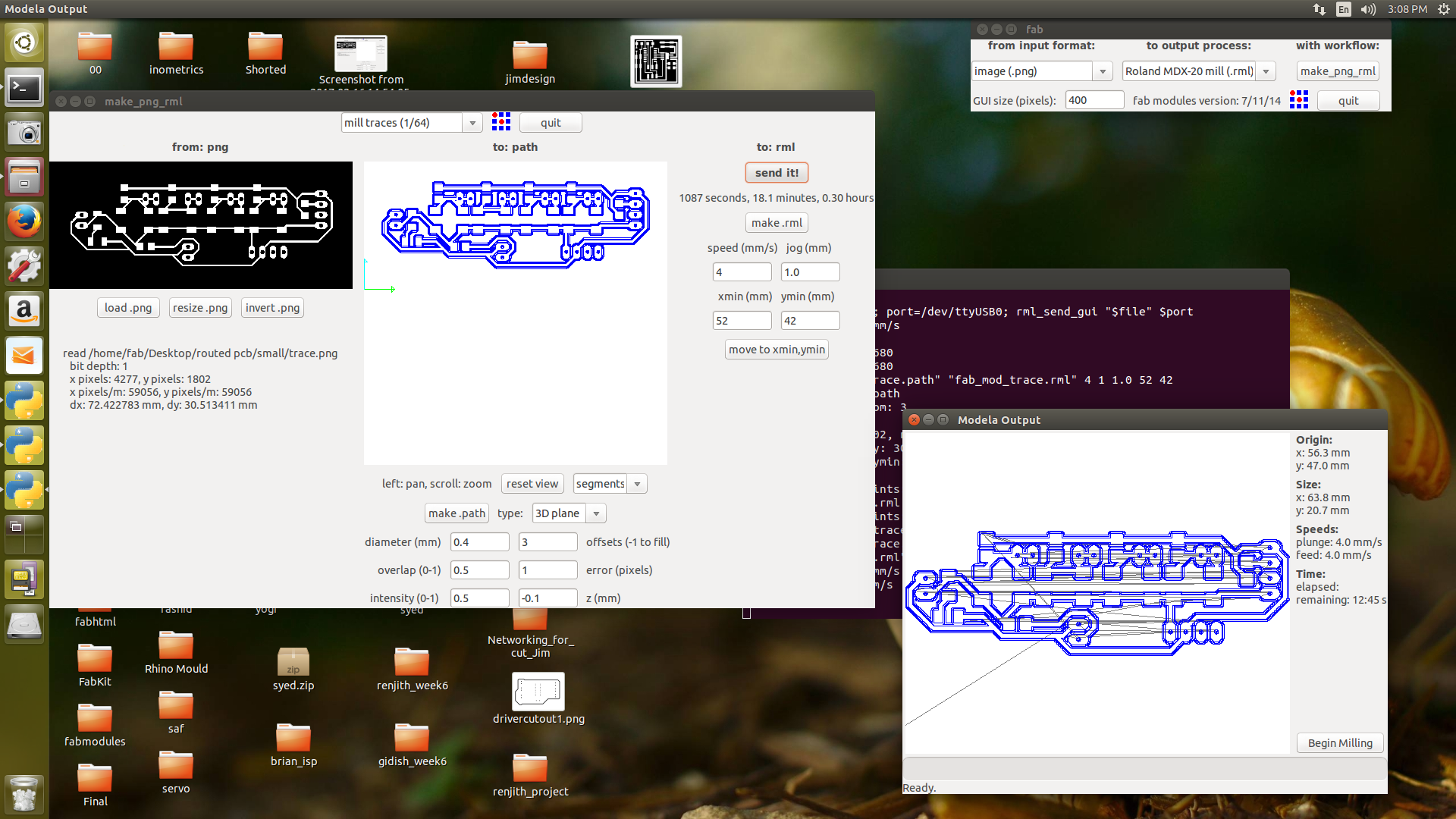
Then i had planned to make the double sided pcb on Modela MDX-20,I have learned how to mill from Ajith Kumar as he already made a double sided PCB board for his project i was able to learn it easily from him.I made a setup for making the double sided pcb's. First we need to fix the X and Y origins so that it won't change while doing the bottom layer.
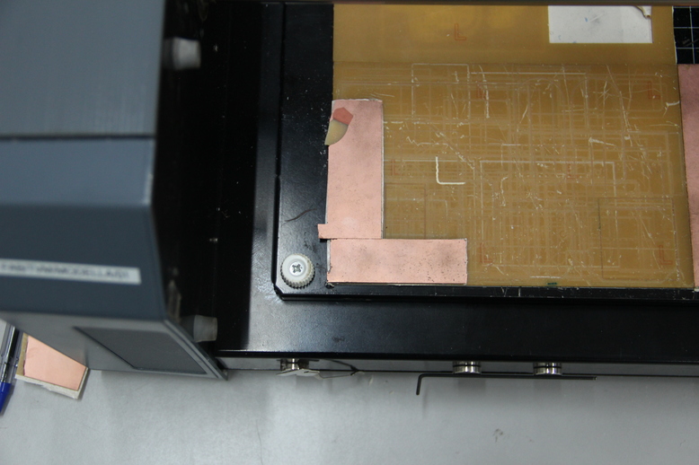
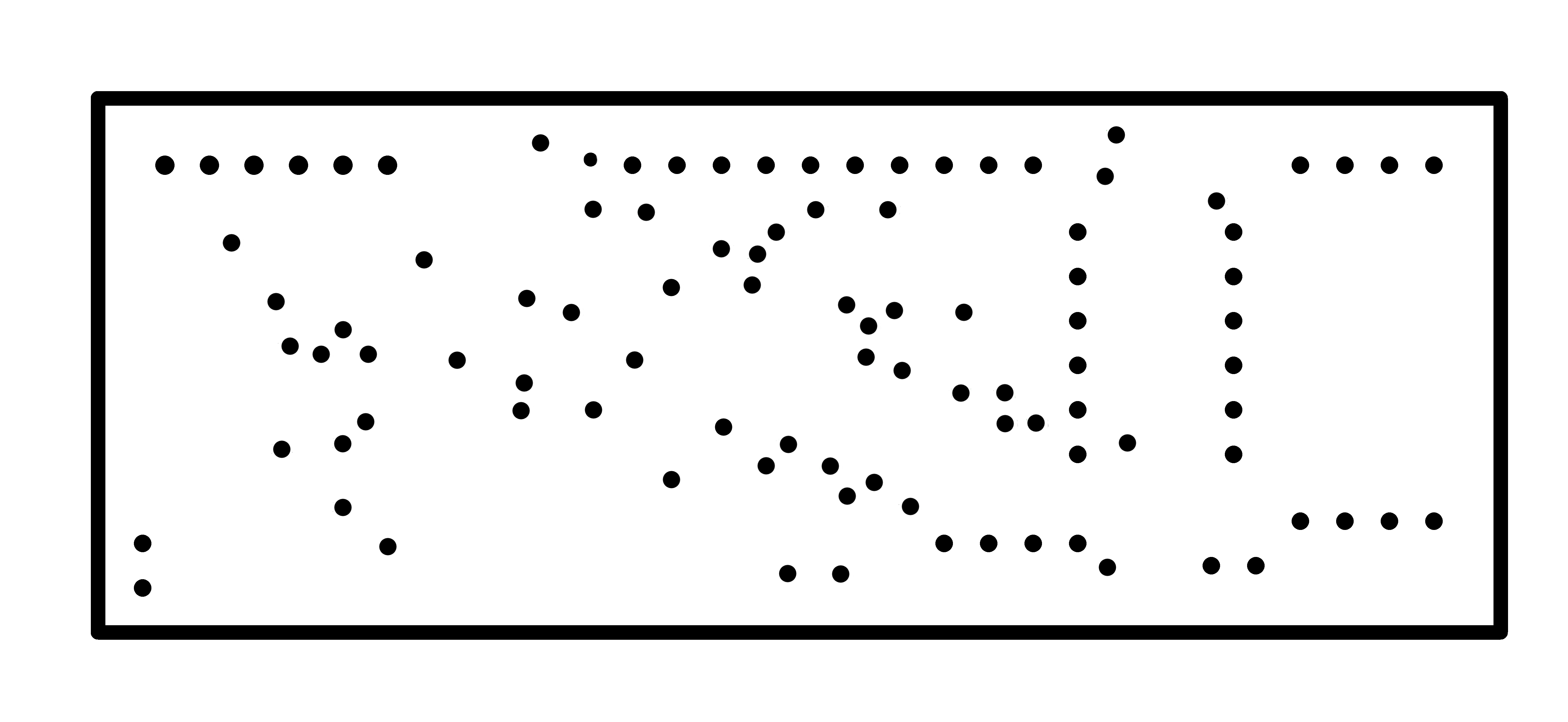
After fixing the X and Y origins i have done some trials to findout the exact coordinates by drilling a 0.8mm hole on the top and bottom of the pcb, for that i have created a small circular dot in gimp and exported into png file. checked the orientation of the holes and done some more trials to match the hole orientations. Finally i found the X and Y origins and then fixed actual pcb.
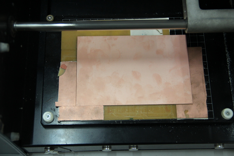
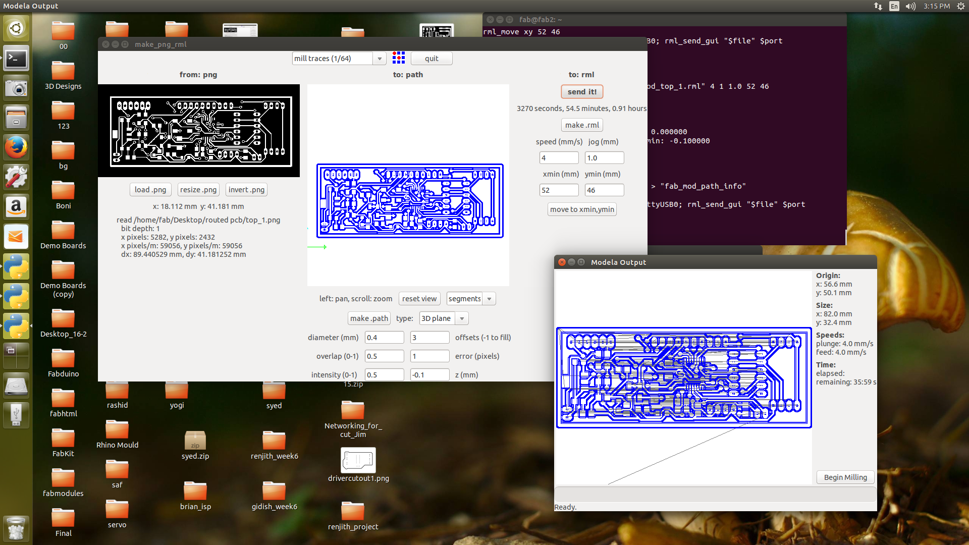
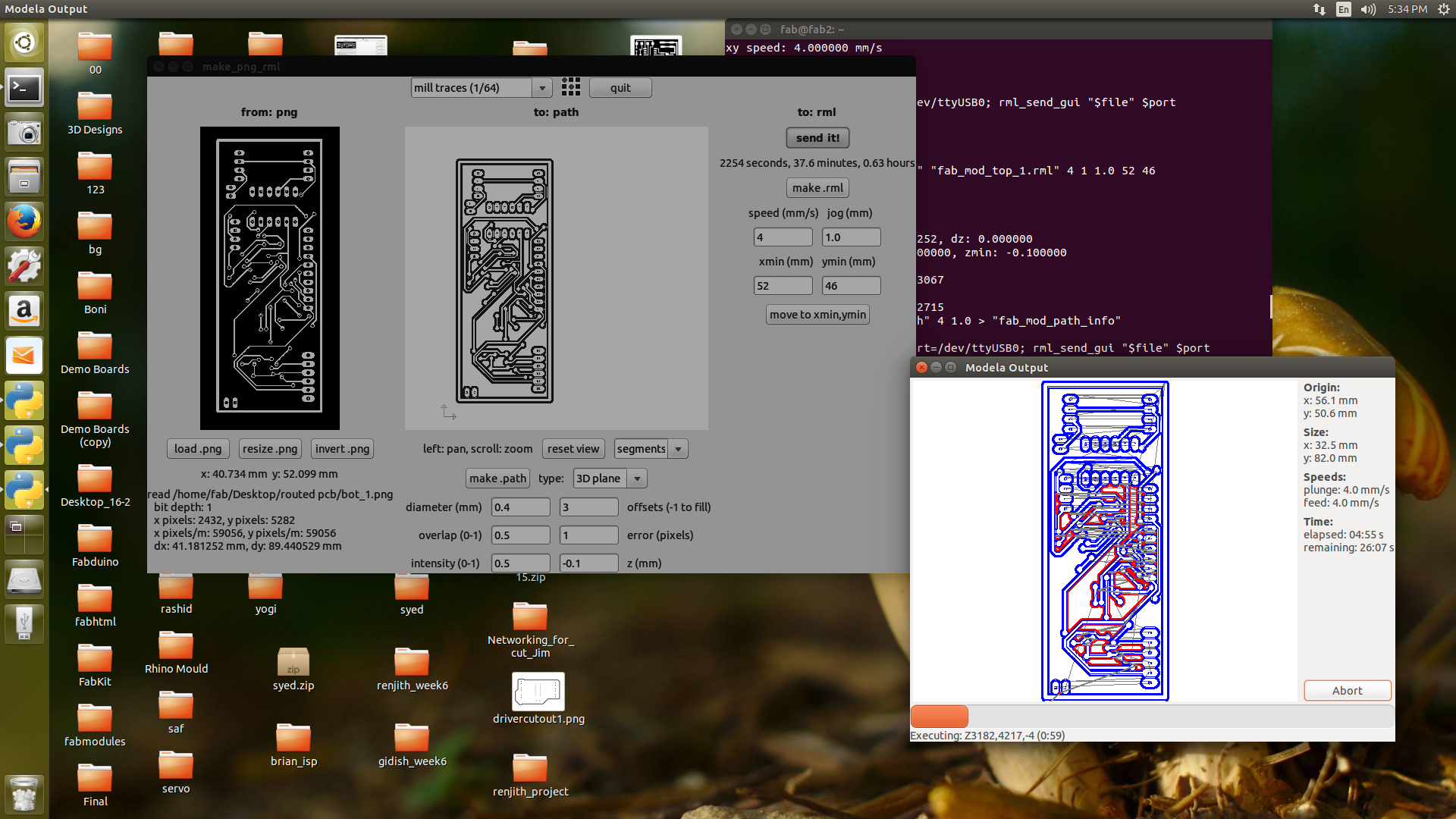
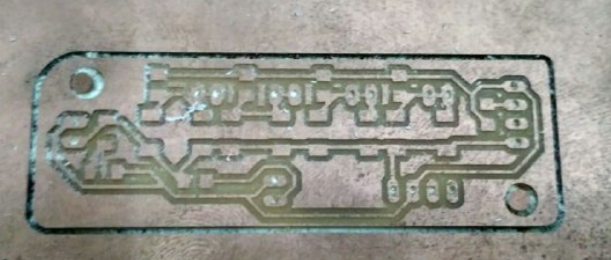
The top layer png image were opened in fab modules and milled the board using 1/64 (0.4mm) bit. The pcb milling of top layer and after the completion of toplayer is shown in the below image.
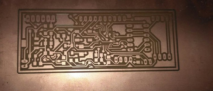
In this step i need to mill the bottom layer of the pcb, for that what i did is i flipped the bottom layer mill traces image horizontally and rotated it to 90 degree clockwise as shown below and like wise i placed the pcb on the bed of modela.
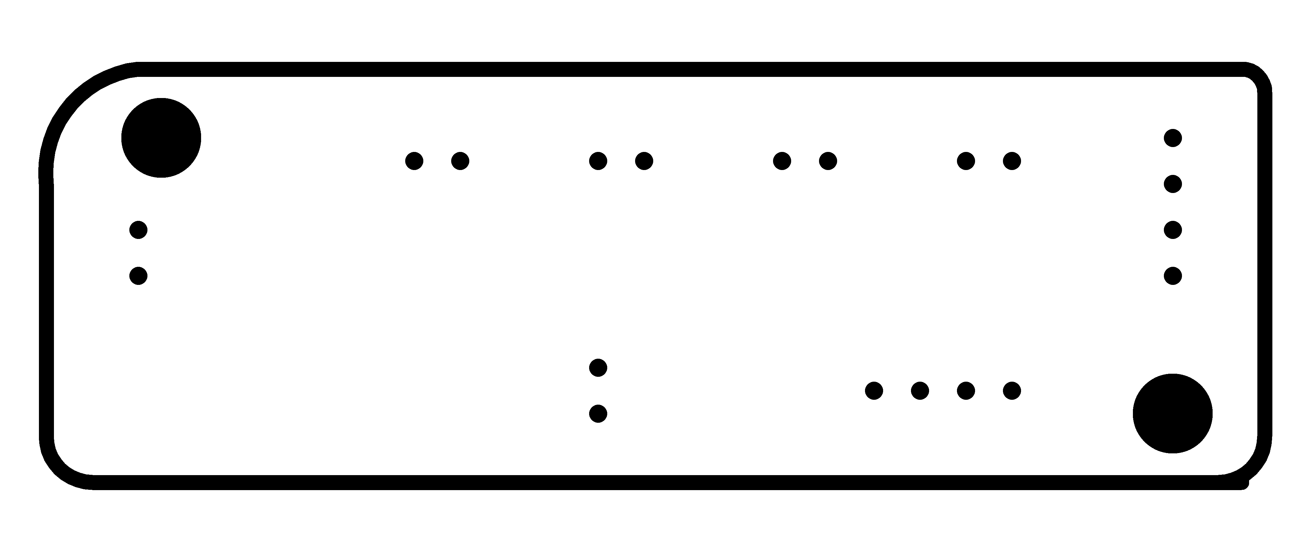
After milling the top and bottom layers, placed the top layer back on to the bed of modela. Then opened the cutout image(png) file in fab modules and changed the bit to 1/32mil(0.8mm) and processed. The final pcb after milling and cutting is given below. In this you can see that slight variations in the hole is there, but as it is very small i can adjust it. Some tarcks were shorted in the usb connector area due to the clearence issue. I seperated it using a knief
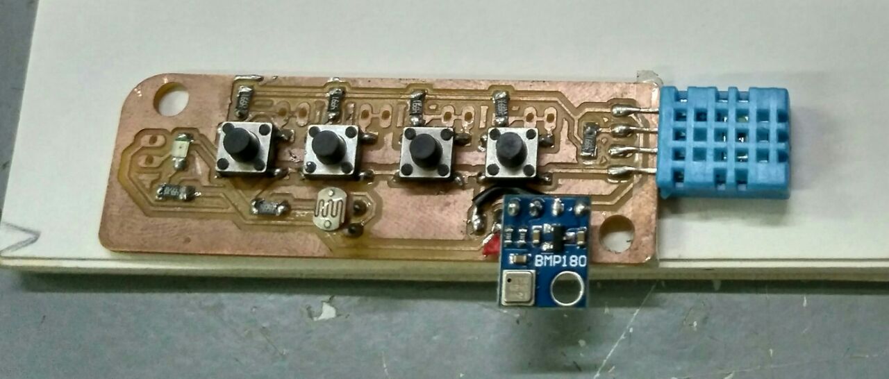
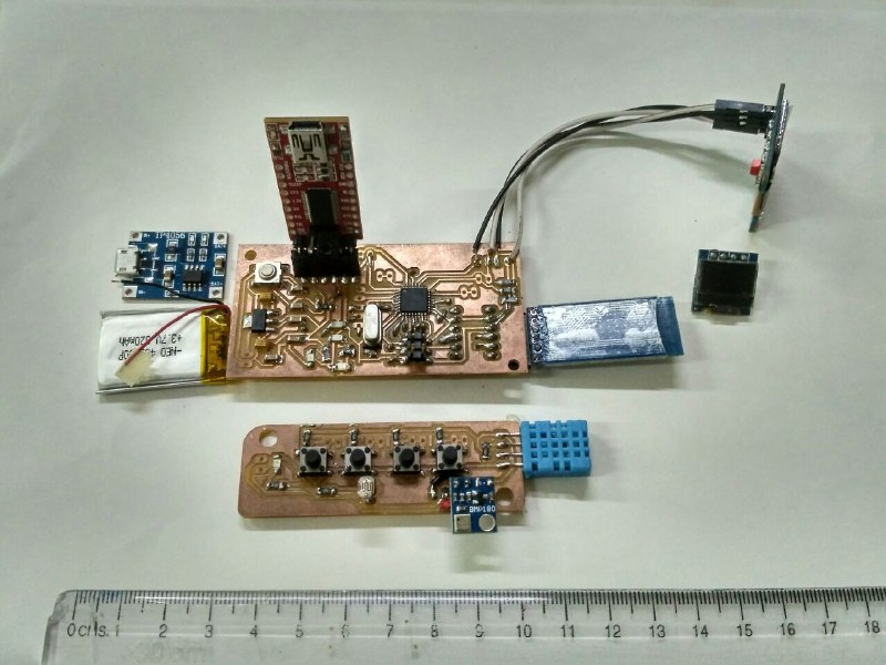
Now i have also designed a seprate board for the switches and sensors that also i have designed in the eagle and i have manually routed it that also i have milled
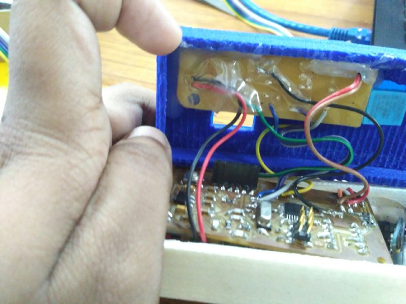
Soldering the Electronic Components
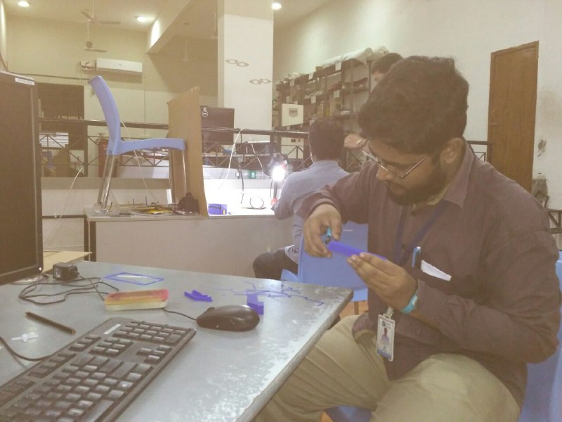
After completing the pcb milling, i did the via soldering . All the top and bottom traces were interconnected with vias and these vias need to be connected using wires. I have used the Single Strand Wire which is took from the Networking wire and i have sucessfully completed the vias and continutity checked using the multimeter
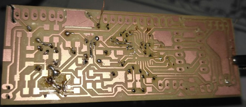
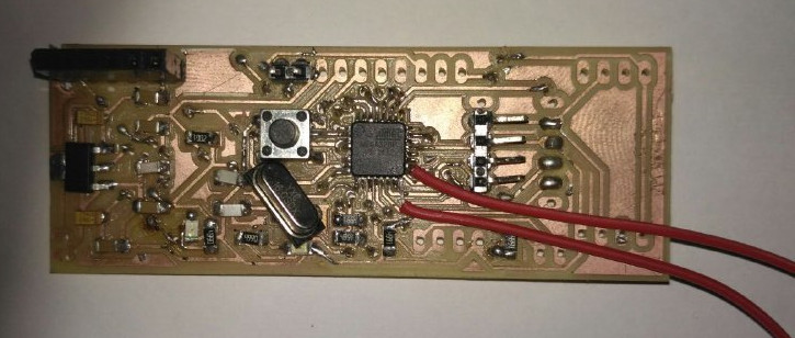
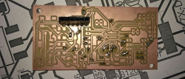
After soldering i have thought i can upload the frimware and program from the ftdi and i was not aware its not possible without having a frimware in it i haven't added a ISP header to my board to reduce the size ,then i got to understand all my 4days hardwork is gone. i also tried to tap the vies from SCK and MOSI to get the pins required for the programming but unfortunately something went wrong and i was unable to upload the frimware and code so i have decided to make a single sided board for the time constrain ,i have made changes in the board design and DRC and have rearranged the components and routed manually and selected autoroute process.
Mean while i have soldered the small board which has the sensors and switches
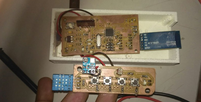
Now i have milled the new main board as per the changed design and i have soldered it
i had slight issue in the connecting some wires in this as single sided board i have made some manual vias under the board and sucessfully soldered the board
Now sucessfully i have completed the soldering and i can program the board that can be found under the programming section
Thus the electronic production is come to an end i was able to complete the main controller board part
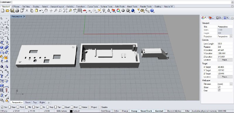
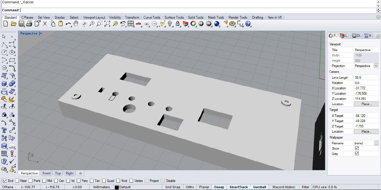
Computer Adided Design
Before going into the Computer aided design i had done the paper prototyping to understand how i can best fit the components in the case.That was very useful
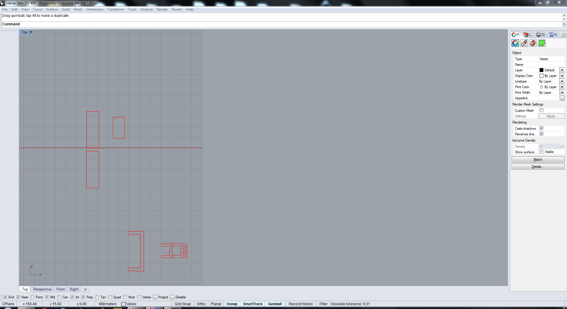
I have used Rhino Software for creating the casing for my data glass and i have shown the design files screenshots here and i have attached the design files for download
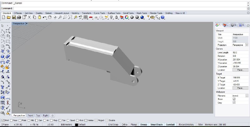
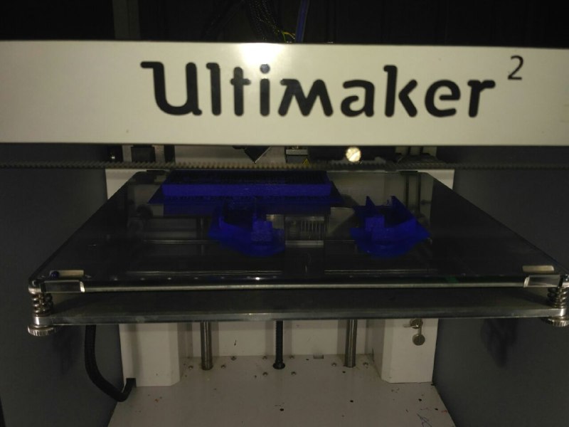
3D Printing
I have used the Ultimaker 2 for 3D Printing the parts which i have designed in the Rhino software are saved as STL files.and those are available in the download section in conclusion
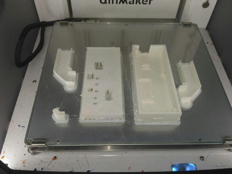
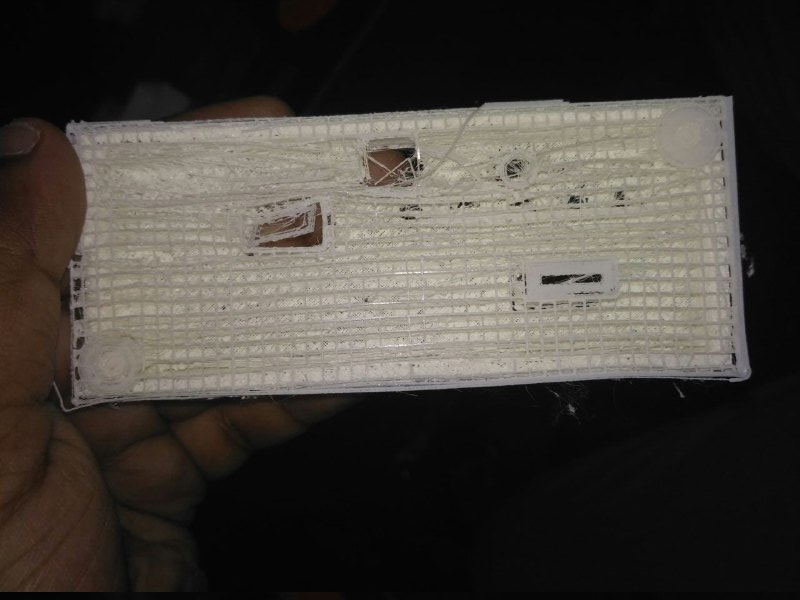
I had an issue with the design of the top layer which thickness is very low and the optics holder has light coming from outside because it is white so i had reprented
Now Finally i have compeleted the 3D Printing so almost the projects to be done are completed
Integration
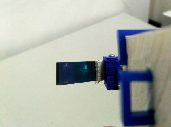
I have Integrated all components to fit insde the case and i had done the connections between switches and the main board with ribbon cable the setp by step setup
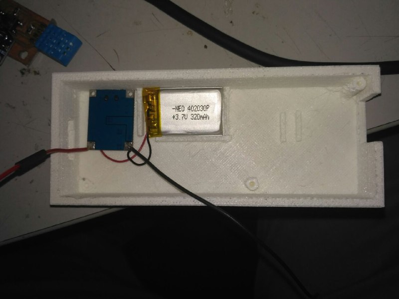
I have put the lense as per the focal length tested
LASER Cutting
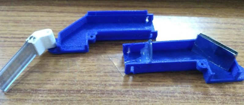
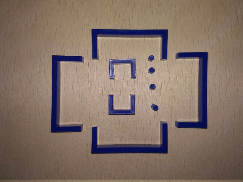
I have planned to put the screws to fasten the Data Glass two parts due to space constrain i am unable so,i have designed a C-clamp which can hold the top and botton parts together and also the buttons went inside to i have designed the small cylinders shapes so i can stick them on top of buttons.and also glass holder small c-clamps also i have designed the reflector with 2mm acrylic sheet and i have cutted using the Laser Cutter. The original design files are added in conclusion page.
Finshing and Packaging
Vinyl Cutting
I have designed a top layer to cut on vinyl sheet to cover wide holes and make it neat for final stickering.

Finally the product is almost ready

Finally i have made the my project looks completed
Laser Cutted carrying/Storage case
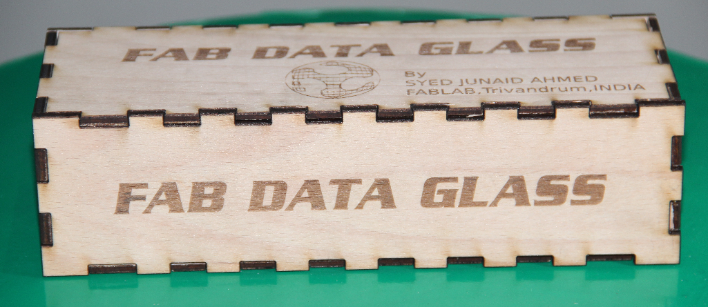
i thought to make a storage case for FAB DATA GLASS for making it safe.
With this my project completes and i have used all the skills and also i have uploaded the necessary download files in the conclusion page.
Bill Of Materials
| Sl.No | Components | Qty(Nos) | Cost per Item ₹ (INR) | Total Price |
|---|---|---|---|---|
| 1 | Atmega328P-AU | 1 | 110.00 | 110.00 | 2 | AMSS117 3.0 | 1 | 35.00 | 35.00 |
| 3 | Resistor 4.9k | 10 | 0.25 | 2.5 |
| 4 | Resistor 499Ohms | 2 | 0.25 | 0.50 |
| 5 | Resistor 10kOhms | 2 | 0.25 | 0.50 |
| 6 | Capacitor- 0.1uF, 1206SMD | 5 | 4.00 | 20.00 |
| 7 | Capacitor- 10uF, 1206SMD | 2 | 4.00 | 8.00 |
| 8 | tactile switch, 1206SMD | 5 | 3.00 | 15.00 |
| 9 | Capacitor-22pF, 1206SMD | 2 | 4.00 | 8.00 |
| 10 | Crystal-16MHz SMD/Leaded | 1 | 15.00 | 15.00 |
| 11 | LED's Red | 2 | 1.00 | 2.00 |
| 12 | LED's Green | 1 | 1.00 | 1.00 |
| 13 | DHT11 Sensor | 1 | 200 | 200 |
| 14 | BMP180 Sensor | 1 | 310 | 310 |
| 15 | LDR | 1 | 15 | 15 |
| 16 | Li-Po3.3V 280mAh Battery | 1 | 100 | 100 |
| 17 | Li-Po Battery Charger | 1 | 75 | 75 |
| 19 | Acrlic Mirror 1SqFeet | 1 | 150 | 150 |
| 20 | pin header | 20 | 5 | 5 |
| 21 | slide switch | 1 | 10 | 10 |
| 22 | Push button switch SMD | 1 | 30.00 | 30.00 |
| 23 | ISP Header | 1 | 10.00 | 10.00 |
| 24 | Lens | 1 | 45.00 | 45.00 |
| Total Cost Of componenets in ₹ (INR) | ₹ 1017.50 or 16 USD |
Programming and Output
i have gone through all the basic sample codes for the DHT11,BMP180 ,Reading Lux values from LDR and finally able to compile the code and made it up and running.
Here is the code which i have used to programming the FAB DATA GLASS
- #include <Wire.h>
- #include <Adafruit_BMP085.h>
- #include <DHT.h>
- #include "U8glib.h"
- U8GLIB_SSD1306_128X64 u8g(U8G_I2C_OPT_NO_ACK); // Display which does not send AC
- #define DHTPIN 2
- #define DHTTYPE DHT11
- DHT dht(DHTPIN, DHTTYPE);
- Adafruit_BMP085 bmp;
- // define pins to be used
- int S1 = 3; //switch 1
- int S2 = 4;
- int S3 = 5;
- bool first = true;
- float hum = 0.0;
- float temp = 0.0;
- float hIndex = 0.0;
- bool dht_test(float* humPerc, float* tempF, float* heatIndex);
- int sensorValue = 0;
- unsigned int curOutputValue = 0;
- unsigned int lastOutputValue;
- float pressure = 0.0;
- float tempC = 0.0;
- float altitude = 0.0;
- void BmpSensorRead(float* pressure, float* tempC, float* altitude);
- void DisplayPresTemp(float* pressure, float* tempC, float* altitude);
- void setup() {
- // initialize the digital pins.
- // assume switches will wire from ground to input pins
- pinMode(S1, INPUT_PULLUP);
- pinMode(S2, INPUT_PULLUP);
- pinMode(S3, INPUT_PULLUP);
- Serial.begin(9600);
- dht.begin();
- lastOutputValue = ~curOutputValue;
- // assign default color value
- if (u8g.getMode() == U8G_MODE_R3G3B2)
- {
- u8g.setColorIndex(255); // white
- }
- else if (u8g.getMode() == U8G_MODE_GRAY2BIT)
- {
- u8g.setColorIndex(3); // max intensity
- }
- else if (u8g.getMode() == U8G_MODE_BW)
- {
- u8g.setColorIndex(1); // pixel on
- }
- else if (u8g.getMode() == U8G_MODE_HICOLOR)
- {
- u8g.setHiColorByRGB(255, 255, 255);
- }
- for (int a = 0; a < 30; a++)
- {
- u8g.firstPage();
- do
- {
- u8g.setFont(u8g_font_fub11);
- u8g.setFontRefHeightExtendedText();
- u8g.setDefaultForegroundColor();
- u8g.setFontPosTop();
- u8g.drawStr(4, a, "FAB DATA GLASS");
- }
- while (u8g.nextPage());
- }
- delay(3000);
- if (!bmp.begin())
- {
- u8g.firstPage();
- do
- {
- u8g.setFont(u8g_font_fub11);
- u8g.setFontRefHeightExtendedText();
- u8g.setDefaultForegroundColor();
- u8g.setFontPosTop();
- u8g.drawStr(4, 0, "FAB DATA GLASS");
- u8g.drawStr(4, 20, " ERROR!");
- }
- while (u8g.nextPage());
- Serial.println("FAB DATA GLASS, ERROR!");
- while (1) {}
- }
- }
- void HumMeter(float* humPerc, float* temp, float* heatIndex)
- {
- u8g.setFont(u8g_font_fub11);
- u8g.setFontRefHeightExtendedText();
- u8g.setDefaultForegroundColor();
- u8g.setFontPosTop();
- u8g.drawStr(4, 0, "Hum %");
- u8g.setPrintPos(80, 0);
- u8g.print(*humPerc);
- #ifdef METRIC
- // if metric system, display Celsius
- u8g.drawStr(4, 20, "Temp C");
- #else
- //display Farenheit
- u8g.drawStr(4, 20, "Temp F");
- #endif
- u8g.setPrintPos(80, 20);
- u8g.print(*temp);
- u8g.drawStr(4, 40, "Heat Ind");
- u8g.setPrintPos(80, 40);
- u8g.print(*heatIndex);
- }
- bool dht_test(float* humPerc, float* temp, float* heatIndex)
- {
- // Wait a few seconds between measurements.
- delay(2000);
- *humPerc = 0;
- *temp = 0;
- *heatIndex = 0;
- // Reading temperature or humidity takes about 250 milliseconds!
- // Sensor readings may also be up to 2 seconds 'old' (its a very slow sensor)
- float h = dht.readHumidity();
- // Read temperature as Celsius (the default)
- float t = dht.readTemperature();
- // Read temperature as Fahrenheit (isFahrenheit = true)
- float f = dht.readTemperature(true);
- // Check if any reads failed and exit early (to try again).
- if (isnan(h) || isnan(t) || isnan(f))
- {
- Serial.println("Failed to read from DHT sensor!");
- return false;
- }
- // Compute heat index in Fahrenheit (the default)
- float hif = dht.computeHeatIndex(f, h);
- // Compute heat index in Celsius (isFahreheit = false)
- float hic = dht.computeHeatIndex(t, h, false);
- Serial.print("Humidity: ");
- Serial.print(h);
- Serial.print(" %\t");
- Serial.print("Temperature: ");
- Serial.print(t);
- Serial.print(" *C ");
- Serial.print(f);
- Serial.print(" *F\t");
- Serial.print("Heat index: ");
- Serial.print(hic);
- Serial.print(" *C ");
- Serial.print(hif);
- Serial.println(" *F");
- *humPerc = h;
- #ifdef METRIC
- // metric system, load degree celsius
- *temp = t;
- *heatIndex = hic;
- #else
- *temp = f;
- *heatIndex = hif;
- #endif
- return true;
- }
- void LightMeter(uint16_t percentLight)
- {
- u8g.setFont(u8g_font_fub17);
- u8g.setFontRefHeightExtendedText();
- u8g.setDefaultForegroundColor();
- u8g.setFontPosTop();
- u8g.drawStr(4, 0, "Light %");
- u8g.drawStr(4, 20, "Meter");
- u8g.drawFrame(4, 40, 122, 24);
- u8g.drawBox(8, 44, (114 * percentLight / 100), 16);
- //
- if (percentLight > 99)
- {
- u8g.setPrintPos(90, 15);
- }
- else
- {
- u8g.setPrintPos(100, 15);
- }
- u8g.print(percentLight);
- }
- void DisplayPresTemp(float* pressure, float* tempC, float* altitude)
- {
- u8g.firstPage();
- do
- {
- u8g.setFont(u8g_font_fub11);
- u8g.setFontRefHeightExtendedText();
- u8g.setDefaultForegroundColor();
- u8g.setFontPosTop();
- u8g.drawStr(2, 0, "Pressure");
- u8g.setPrintPos(75, 0);
- u8g.print(*pressure);
- u8g.drawStr(4, 20, "Temp C");
- u8g.setPrintPos(75, 20);
- u8g.print(*tempC);
- u8g.drawStr(4, 40, "Altitude");
- u8g.setPrintPos(75, 40);
- u8g.print(*altitude);
- }
- while (u8g.nextPage());
- }
- void BmpSensorRead(float* pressure, float* tempC, float* altitude)
- {
- *tempC = bmp.readTemperature();
- Serial.print("Temperature = ");
- Serial.print(*tempC);
- Serial.println(" *C");
- *pressure = bmp.readPressure() / 100.0;
- Serial.print("Pressure = ");
- Serial.print(*pressure / 100.0);
- Serial.println(" hPa");
- // Calculate altitude assuming 'standard' barometric
- // pressure of 1013.25 millibar = 101325 Pascal
- *altitude = bmp.readAltitude();
- Serial.print("Altitude = ");
- Serial.print(*altitude);
- Serial.println(" meters");
- }
- void loop() {
- if (!digitalRead(S1))
- {bool result = dht_test(&hum, &temp, &hIndex);
- if (first)
- {
- // skip displaying readings first time, as its stale data.
- first = false;
- }
- else
- {
- if(result == false)
- {
- u8g.firstPage();
- do
- {
- // sensor error
- u8g.setFont(u8g_font_fub11);
- u8g.setFontRefHeightExtendedText();
- u8g.setDefaultForegroundColor();
- u8g.setFontPosTop();
- u8g.drawStr(10, 30, "Sensor Error");
- }
- while (u8g.nextPage());
- }
- else
- {
- u8g.firstPage();
- do
- {
- HumMeter(&hum, &temp, &hIndex);
- }
- while (u8g.nextPage());
- }
- }
- }
- if (!digitalRead(S2))
- { BmpSensorRead(&pressure, &tempC, &altitude);
- DisplayPresTemp(&pressure, &tempC, &altitude);
- delay(1000);
- }
- if (!digitalRead(S3))
- {
- sensorValue = analogRead(A0);
- Serial.print("input :");
- Serial.println(sensorValue);
- // map input values between 0 t0 100%
- curOutputValue = map(sensorValue, 0, 690, 0, 100);
- if (curOutputValue > 100)
- {
- curOutputValue = 100;
- }
- if (lastOutputValue != curOutputValue)
- {
- lastOutputValue = curOutputValue;
- u8g.firstPage();
- do
- {
- LightMeter(curOutputValue);
- }
- while (u8g.nextPage());
- }
- }
- }
Output
i have tested output of the device
here you see the intial testing
here you see the final output after programming and i had a problem with recording from reflector as the intensity is very less that is easily visble to naked eye but difficult to capture from mobile phone camera so i have opened the case and recorded the video
