What are Output Devices ?
An output device is any piece of hardware item which utilizes whatever data and commands from your micro controller/processor in order to perform a task. This leads to the results of data processing carried out by an information processing system (such as a microcontroller) which converts the electronically generated information into human-undestandable form
The output is what results from an electronic circuit. Any of the following components may be used as outputs:
Detail explanation of the Electronic Components
ATTiny 45 Multi Board
i have used the ATTiny45 for this weeks assignment i have made a multi board where i have connected the all the pins to one pin header so i can use all the I/O pins as per the required i have included the place holder for the OLED display and the speaker
i had used the eagle as per the experience from the electronics design week and now below yoiu can see the snapshots
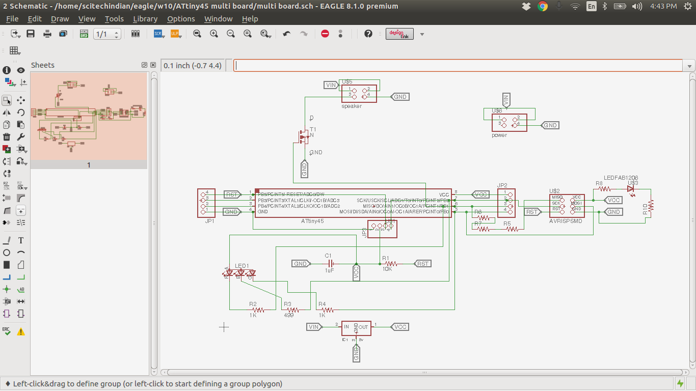
board designed in Eagle schematics
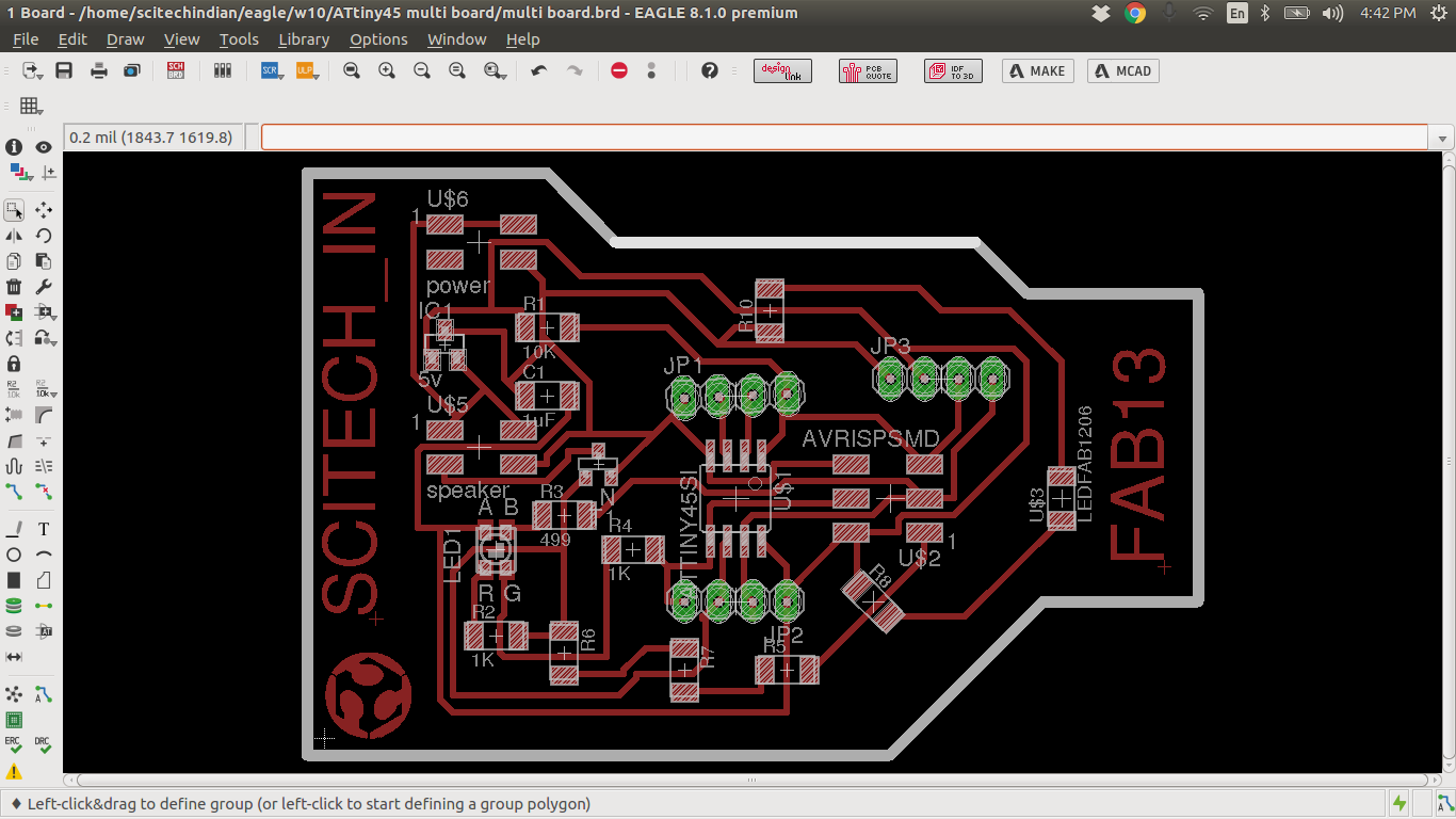
board designed in Eagle after route
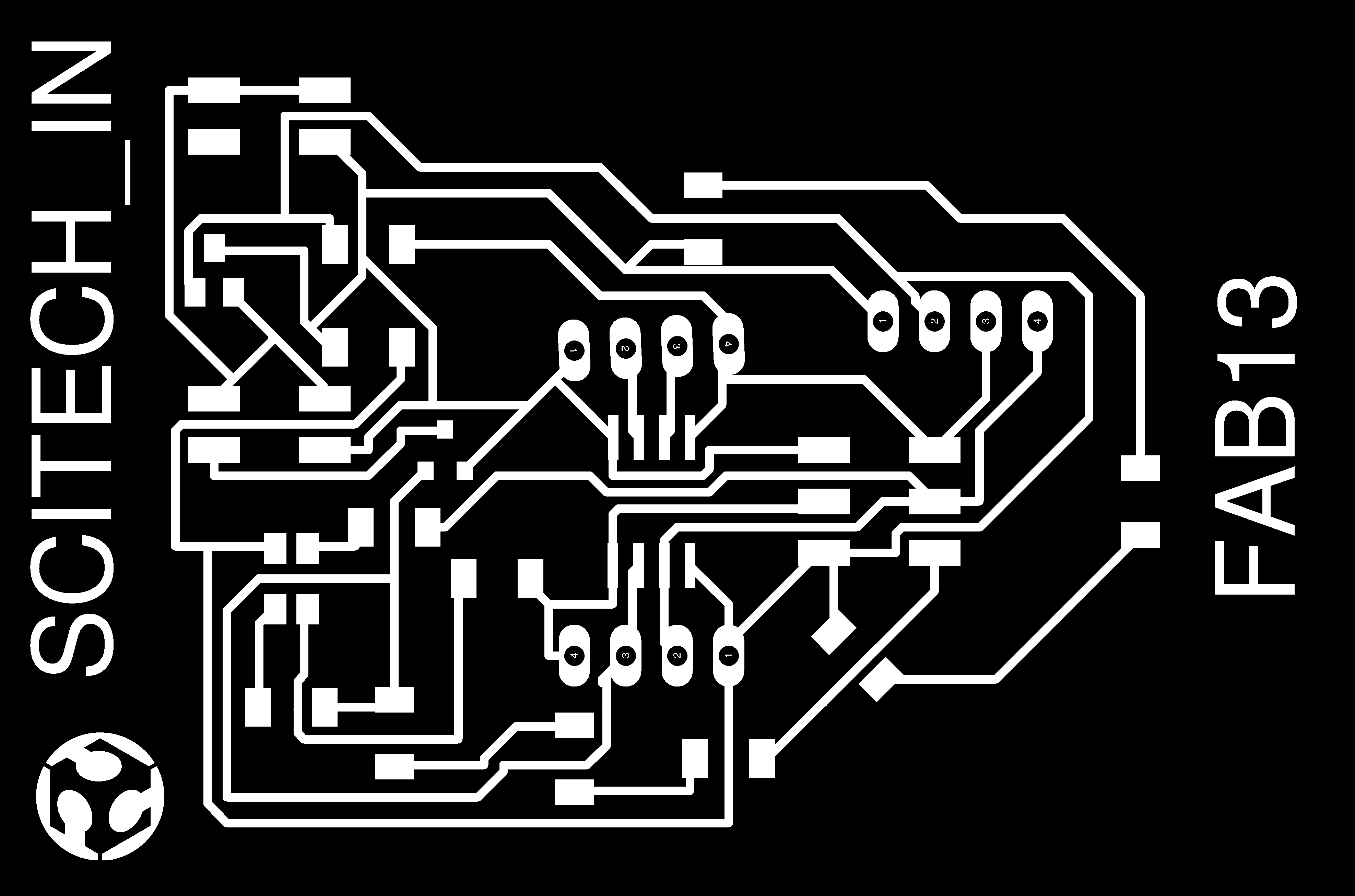
traces image for milling
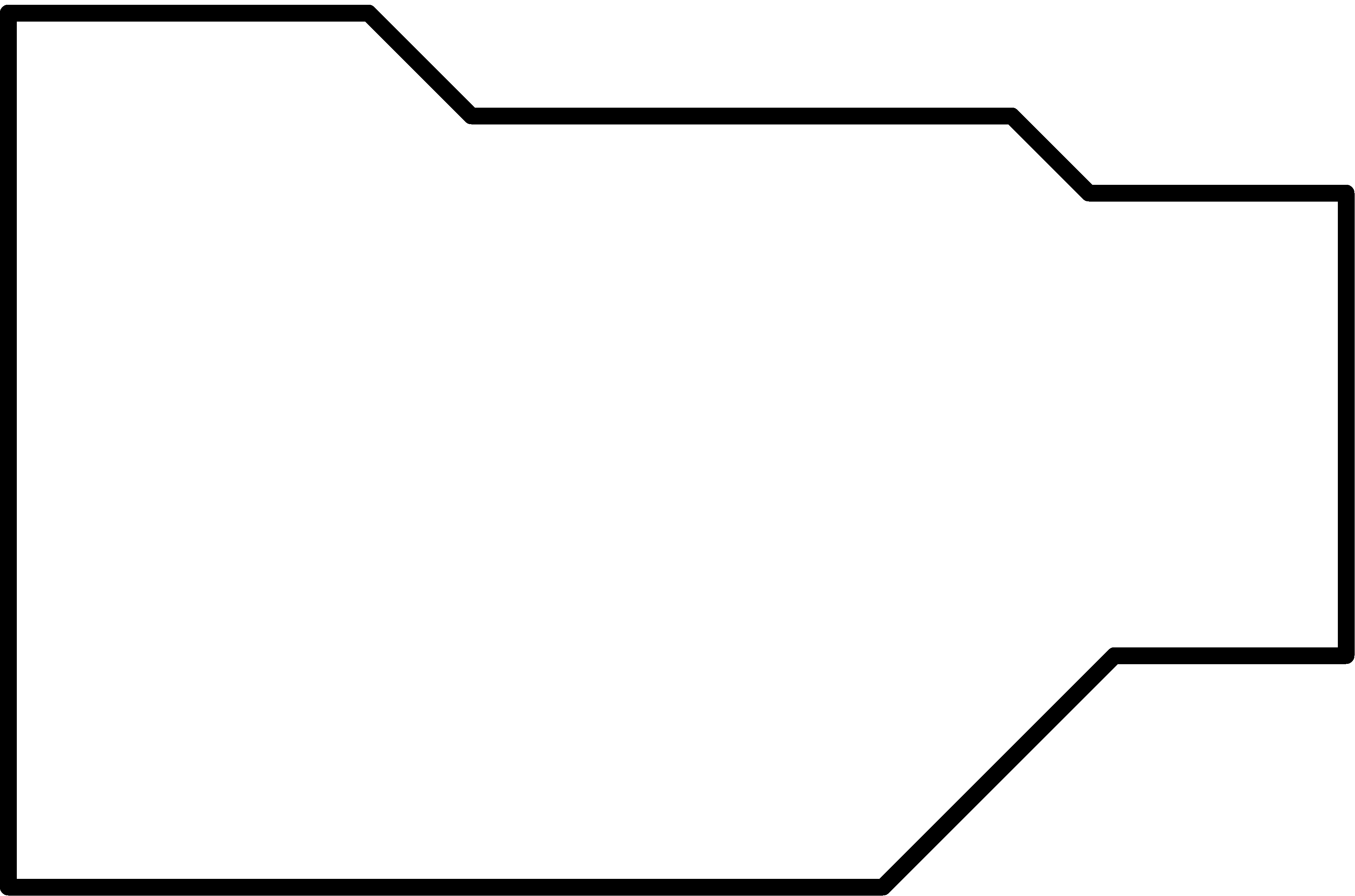
Cut part image for milling
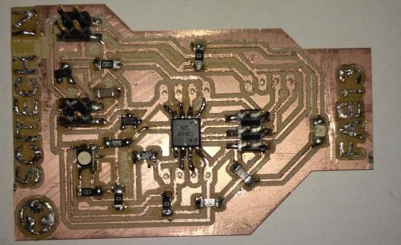
After the milling process is completed i have been soldered as the electronics production week and finally i have the complete board
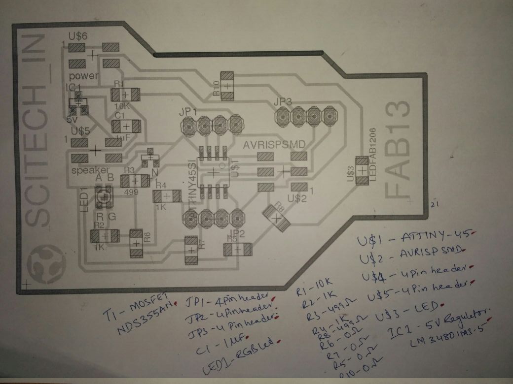
part list image for Soldering
Now Download the Orginal files Eagle files and PNG files
We used arduino code to test and control the RGB LED.
RGB LED glows as per pattern
Here you can find the code used for the programming
- int redPin = 1;
- int greenPin = 2;
- int bluePin = 0;
- #define COMMON_ANODE
- void setup()
- {
- pinMode(redPin, OUTPUT);
- pinMode(greenPin, OUTPUT);
- pinMode(bluePin, OUTPUT);
- }
- void loop()
- {
- setColor(255, 0, 0);
- delay(1000);
- setColor(0, 255, 0);
- delay(1000);
- setColor(0, 0, 255);
- delay(1000);
- setColor(255, 255, 0);
- delay(1000);
- setColor(80, 0, 80);
- delay(1000);
- setColor(0, 255, 255);
- delay(1000);
- }
- void setColor(int red, int green, int blue)
- {
- #ifdef COMMON_ANODE
- red = 255 - red;
- green = 255 - green;
- blue = 255 - blue;
- #endif
- analogWrite(redPin, red);
- analogWrite(greenPin, green);
- analogWrite(bluePin, blue);
- }
Hero Shot
Now here we comes to the Hero Shot of this Week
The ATTiny 45 Multi Board
